Abstract
In this paper, an initial analysis of cost, energy and carbon dioxide (CO2) emissions that occur in producing a unique aluminium hat using single point incremental forming (SPIF) for two scenarios is performed. The aluminium hat was custom designed and made from Al-3003 O and is formed using a custom steel alloy SPIF tool and vertical computer numeric control (CNC) mill. The second scenario (S2) involved doubling the feed rate and step down increment of the first scenario (S1), as well as using an eco-benign lubricant. The cost and energy used for the SPIF process without labour were found to be $4.48 and 4580 kJ (1.27 kWh) for S1 and $4.10 and 1420 kJ (0.39 kWh) for S2, respectively. The respective direct electrical energy required for making the hat was only 16% and 27% of the total required process energy for S1 and S2. Using virgin or traditional emission intensity inputs for the tool, lubricant, workpiece and energy, the embodied CO2 from the process was found to be 4.48 kg CO2e for S1. However, using 33% recycled aluminium, an eco-benign lubricant and a remanufactured tool resulted in an embodied CO2 of 3.24 kg CO2e or a 28% CO2 savings for the same process parameters. Similarly, in S2, the embodied CO2 was found to be 4.28 kg CO2e for traditional inputs and 3.09 kg CO2e for modified inputs. Comparing S1 traditional and S2 modified, there is a reduction in energy use and CO2 by 69% and 31% accordingly. As expected, the stock material dominated the embodied CO2 and cost, but the energy consumed was the next highest contributor. Future work will consider optimal parameters for cost, energy and embodied CO2 minimisation.
1. Introduction
Energy and carbon dioxide (CO2) emissions have been determined for machining processes in recent work (Gutowski Citation2007, Anderberg et al. Citation2010, Branker et al. Citation2011). However, sheet metal forming remains an area where little has been published on CO2 emissions associated with a specific sheet forming process (Ingarao et al. Citation2011). In this paper, energy and CO2 emissions have been determined for a case in single point incremental forming (SPIF), which is a recently developed sheet metal forming technique that has shown great diversity in potential sheet forming applications (Jeswiet et al. Citation2005, Duflou et al. Citation2008, Crina Citation2010). As the literature continues to characterise this part production technique (Hussain and Gao Citation2007, Duflou et al. Citation2008, Rauch et al. Citation2009, Crina Citation2010, Hamilton Citation2010), it is important to add the energy and cost studies needed to develop commercial strategies. Since manufacturing operations are naturally energy intensive and electricity generated from fossil fuels is a major contributor of CO2 emissions (Jeswiet and Nava Citation2009), it is important to add the energy and CO2 emission analysis to any process characterisation to inform life cycle analysis (LCA) studies (Gutowski Citation2007, Branker et al. Citation2011). Gutowski et al. (Citation2006) showed that the specific energy requirements of manufacturing processes were not constant as assumed in many LCA studies and that the process rate was of key importance. In addition, they showed that ancillary operations add substantially to the energy needed in a manufacturing operation (Gutowski et al. Citation2006). In machining, the process rate often quoted is the material removal rate (MRR), which depends on the feed rate (FD), depth of cut and width of cut of the operation (Gutowski et al. Citation2006, Kalpakjian and Schmid Citation2006, Anderberg et al. Citation2010). In the literature for SPIF, it is not clear what process rate metric comparable to MRR is available. However, the FD and step down increment/step size (ST) in SPIF are some of the parameters known to change the rate at which the process occurs (Jeswiet et al. Citation2005, Duflou et al. Citation2008, Crina Citation2010, Hamilton Citation2010). As such, these will be considered in the study.
The aim of this initial study was to provide an example of how the energy consumption, CO2 emissions and costs can be studied for SPIF and areas of future work. This paper entails the manufacture of a custom made aluminium hat using SPIF as a unique case study to consider the energy, cost and CO2 emission details of the process. A custom made hat was chosen because of the complicated nature of the shape. A distinct breakdown in the electrical energy used in the sheet forming process is the direct energy (E D) and ancillary energy (E A) (Branker et al. Citation2011). The E D will be the theoretical and/or necessary energy required for the process while the E A will be associated with the support systems not directly involved in the process; such as compressed air systems (Diarra et al. Citation2010) or cooling fans. For the E D in this paper, the energy required for sheet deformation and the energy required for the loaded CNC mill spindles and axes are measured and considered together as necessary for the operation.
2. Background information on SPIF
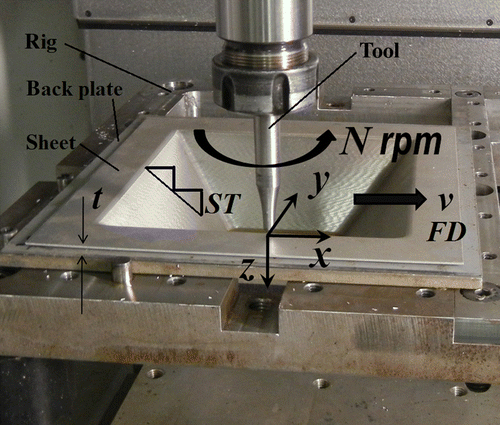
SPIF is a dieless sheet metal forming process that allows sheet metal to be formed without the need for specialised tooling. SPIF employs a solid, hemispherical tool that presses on a sheet moving in a series of successive contours, forming the sheet incrementally into its final shape (Jeswiet et al. Citation2005, Crina Citation2010). SPIF is able to produce both axially symmetric and asymmetric parts, only requiring a rig to hold the sheet metal workpiece. Figure illustrates the basic configuration and terminology for SPIF (Crina Citation2010). Like other machining operations, the FD and ST increment affect the time taken for the process.
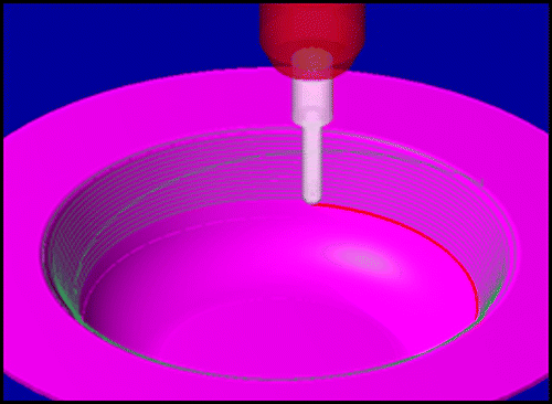
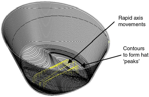
Typically, SPIF is performed on a CNC milling machine that has been converted by adding a sheet holder rig to the table. Toolpaths can be written with any commercially available CAM package. The lack of any specialised tooling means that the only difference between parts is the program run by the mill. Little research has been done on tool wear in SPIF, but there appears to be very little visible wear or deflection in the tool after use. In fact, what is noted is that there is only observable wear in the absence of lubrication (Jeswiet et al. Citation2005, Hamilton Citation2010). The shape of a common toolpath is shown in Figures and . A backing plate serves to support the part and create well-defined edges in the final formed shape (Hamilton Citation2010).
By far the biggest attraction of SPIF is the ability to form complicated custom sheet metal parts with rapid turnaround times and custom tooling is not needed.
3. Methodology
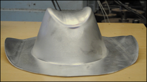
In this study, SPIF was used to create a unique hat from Al-3003 O using a Bridgeport GX 480 vertical mill and a custom steel alloy SPIF tool. In this mill the sheet is held in place on a custom made blank holder, and moves in the horizontal x- and y-axes. The tool moves in the z-axis. The general design process involved drawing the hat detail in SolidWorks™, followed by importing the drawing into MasterCam™. Figure shows the detail for the hat as imported in MasterCam™. In MasterCam™, the SPIF process parameters were set and the program was run. In order to gauge what the energy use in the SPIF process was with and without metal forming loads, the NC program from MasterCam™ was run on the mill with and without stock sheet. Figure shows the finished hat; note that the dimple at the front of the hat naturally develops as a result of the forming process.
The part of the hat that is processed using SPIF has maximum ellipse dimensions of 216 mm (8.5 in.) major diameter and 178 mm (7.0 in.) minor diameter with a maximum height of 102 mm (4.0 in.). The workpiece was a 327 mm (12.875 in.) × 327 mm (12.875 in.) × 1.5 mm (0.059 in.) Al-3003 O sheet. For the experiments, each NC run scenario (with and without stock) was completed three times and then averaged to get the final result. Two run settings were used to illustrate the impact of changing process parameters. The initial SPIF process parameters (Scenario 1, S1) were at a FD of 2032 mm/min (80 in./min), spindle speed (N) of 600 RPM (climb milling) and a ST of 0.254 mm (0.01 in.), with a tool diameter of 635 mm (1/4 in.) and gear oil lubricant (75W-140). These parameters were found to produce a reasonable finish and were the general settings used in the shop. The lubricant is used to reduce the friction of the tool and to allow the SPIF process to occur smoothly (Hamilton Citation2010). In another study, it was found that for a simpler SPIF part, as the FD and ST increment increased, the overall energy use decreased (Branker Citation2011). Thus, a second scenario (S2) was developed by doubling the FD and ST, and increasing the size of the tool to accommodate the increase in ST to maintain the finish (Hamilton Citation2010). Considering the CO2 burden, an eco-benign lubricant derived from used cooking oil (Nava et al. Citation2010) was used instead of the synthetic gear oil. Table summarises the settings for the two scenarios.
Table 1 Summary of experimental parameters.
A graduated measuring cylinder was used to apply the lubricant at the track of the tool and to quantify the amount of lubricant used. A digital scale was used to determine the weights of inputs, e.g. tool and stock. Finally, to measure the energy used by the machine, three OMEGA™ OM-PLCV data loggers with the respective logger interface software were used for the three phases of the power supplied to the machine using the highest resolution available of 1 Hz. The metres were set up to get the line-to-line voltage and the line current. The following Equations (Equation1) and (Equation2
) were used to resolve the effective power used, P
total:
The energy used is then determined by finding the area under the power versus time graphs using the trapezoidal rule on the discrete data. To calculate the embodied CO2 emissions from the process including the stock sheet, the emission intensities (EIs) of reference materials were used as was available in the literature and databases. Once all the data were obtained, the breakdown of energy, cost and embodied CO2 equivalent emissions were determined for the process.
4. Results and analysis
4.1 Energy results
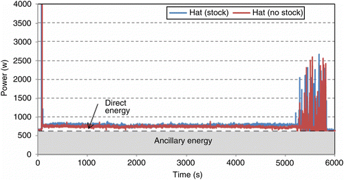
The resolved power usage over time for the S1 process: (a) running the program with load/stock sheet and (b) running the program without stock sheet is shown in Figure .Figure shows the comparison of the two on the same plot showing the E D and E A breakdown. The E A is the shaded area and the E D is above minus the axis positioning at the start and the end. Note that there is a power spike at the beginning of the process when the tool moves rapidly (accelerates and decelerates) to the start point of the program, otherwise called positioning. While the tool is making continuous incremental passes, the energy power profile is roughly constant. Furthermore, in the last stages of the program, where the detail at the top of the hat is being generated, there are several oscillating spikes from rapid axis movements (accelerations and decelerations in addition to moving) as shown in Figure . It is clear that the loaded case uses slightly more energy than the loaded case. Note that the spikes do not fully align and this is likely the result of signal aliasing due to the limited sampling frequency of 1 Hz of the data loggers. Negligible compressed air is used during SPIF and is not accounted for.
The dashed line in Figure indicates the baseline load when the machine is on standby waiting to start an operation. For this process, the baseline measures the ancillary contribution, since only the spindle and axis movements occur additionally during the program. Throughout, the console, fans, light and control system run regardless of the process. Furthermore, for SPIF, the coolant system is not needed. From the plot, it is clear that the SPIF process for making the hat adds a small amount of energy (at the operating parameters used) above the baseline for the deformation and spindle and axis motors. Furthermore, the difference between running the program with stock sheet and without stock sheet is very small, such that the energy for deformation is small in SPIF. The energy used in each plot was resolved by finding the area under each graph.
Table illustrates the energy breakdowns for S1, derived using the trapezoidal rule, and confirms the small additional energy required for the SPIF process above the baseline at the given SPIF parameters. The E A represents roughly 84% of the process energy, which is consistent with other manufacturing process findings (Gutowski et al. Citation2006). The E D represents 16%, made up of 13.8% for spindle and axis movements and 2.6% for deformation energy.
Table 2 Energy profile data for hat made with SPIF process Scenario 1 on Bridgeport™ GX480.
The analysis in Table was repeated for S2. Table summarises the energy use and time in SPIF for the two scenarios, with the standard error reported for the total energy and the total time. From the energy results, the time for the SPIF process in S1 and S2 is 1.59 h (5720 s) and 0.40 h (1456 s), whereas the total process from design to finish takes 3 and 1.81 h, respectively. The average idling (handling) time and positioning of the axes takes 181 s for both settings. Note that in S1, the SPIF process uses 4580 ± 40 kJ whereas S2 with double the FD and ST uses 1420 ± 30 kJ or roughly three times less energy. This relationship can be understood considering that S2 was more than three times faster in terms of total process time. Thus, for a faster process, the contribution of the ancillary energy is reduced. Of the total energy used, the E A in S1 is 84% while it is 73% in S2. The E D contribution increases due to a greater power requirement in driving the axes faster. According to the data, the deformation energy seems to decrease. Considering the standard error and variability in the energy consumption at different times of day and between different days, more work is needed to conclude how the deformation energy changes with changing parameters. Finally, there was no observable difference in finish on the outside of the hat between the two scenarios. However, on the inside of the hat in the detailed portion (‘peaks’), the wider contours taken for the larger step size are clear, although smooth.
Table 3 Summary of energy use and time for two scenarios.
4.2 Cost and CO2 emissions analysis
A basic cost and CO2 emission analysis was performed noting the resource inputs for the hats. Figure illustrates the main part of the process focussed on for the analysis.
Figure 6 Abridged process diagram for hat made from aluminium sheet via SPIF showing process area for CO2 and cost of manufacturing analysis.
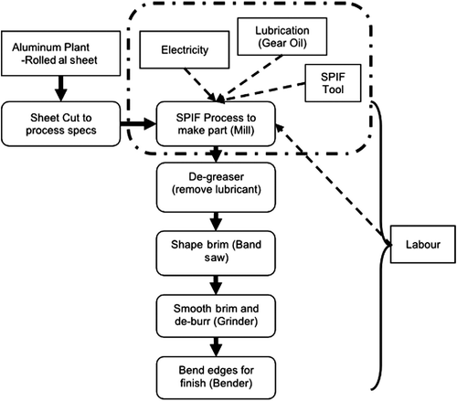
Table indicates the cost breakdown for the hats in the two scenarios. For inputs, minus labour costs, the cost per hat for Scenarios 1 and 2 is $4.48 and $4.10, respectively. The lower cost in S2 is due to the reduced energy use, reduced lubricant use and cheaper eco-benign lubricant. Considering labour, the cost per hat becomes for a one-off hat, $184.48 and $113.15, or for a commercial hat as one of one thousand, $84.48 or $26.94, respectively. Labour cost estimates were made with machine shop staff. The large change in the cost is related to the reduction in time of the process, which reduces the labour contribution per part as shown in Table .
Table 4 Cost breakdown for manufacturing a hat using SPIF for two scenarios.
When considering the CO2 breakdown, the experimental/traditional inputs and potential modified inputs were considered for each scenario. As mentioned earlier, the best available reference material was used to gauge the EI of each input. For example, the world average EI for rolled aluminium sheet is used for the Al-3003 O sheet (Hammond and Jones Citation2011). Virgin rolled aluminium with an EI of 12.15 kg CO2e/kg is used for the traditional analysis, whereas a modified input is rolled aluminium with 33% recycled content with an EI of 8.72 kg CO2e/kg (Hammond and Jones Citation2011). Note that this could be reduced even more with 100% recycled content with an estimated EI of 1.73 kg CO2e/kg (Hammond and Jones Citation2011). For both cases, the electrical grid is in Ontario with an EI of 0.17 kg CO2e/kWh (Environment Canada Citation2010). For the tool, given limited LCA data for manufacturing tools, a mill tool EI is used for the SPIF tool EI. Thus, the traditional input would be a virgin tool with an EI of 6.4 kg CO2e/kg, whereas the modified input would be a remanufactured tool that has been re-grounded five times in its life cycle reducing the EI to 1.3 kg CO2e/kg (Kara Citation2009). Finally, without exact LCA data on the Quaker State lubricant, mineral gear oil is used as the reference material with an EI of 3.30 kg CO2e/L (Nava et al. Citation2010). The used cooking oil ester from Germany used in S2 has an EI of 0.51 kg CO2e/L (Nava et al. Citation2010). In the same study (Nava et al. Citation2010), it was found that the mineral oil and the used cooking oil ester had very similar coefficients of friction, which would likely result in the same finish.
Table summarises the embodied CO2 breakdown from the process for the hat in S1 with traditional/experimental inputs and modified inputs as described above. Table summarises the same for S2. For S1, the total embodied CO2 is found to be 4.48 kg CO2e. If a carbon price of $50/tonne CO2 were applied, this would be an additional cost of $0.22 per hat. As expected, the material of the workpiece dominated the CO2 due to the part with a value of 4.20 kg CO2e. When theoretical modification to the inputs is considered, using 33% recycled content Al, used cooking oil and remanufactured tool, the impact reduces to 3.24 kg CO2e or by 28%. This would save $0.06 per hat at $50/tonne CO2.
Table 5 CO2 contribution breakdown for Scenario 1 (S1) SPIF hat process.
Table 6 CO2 contribution breakdown for Scenario 2 (S2) SPIF hat process.
For S2, the traditional total embodied CO2 is found to be 4.28 kg CO2e, which is 4.5% lower than the traditional S1 due to the reduced energy use, use of the eco-benign lubricant and reduction in overall lubricant use. If a carbon price of $50/tonne CO2 were applied, this would be an additional cost of $0.21 per hat. Again, the stock material has the highest CO2 contribution of 4.20 kg CO2e. However, when theoretical modification to the inputs is considered, using 33% recycled content Al and a remanufactured tool, the impact reduces to 3.09 kg CO2e or by 28% ($0.06 reduction at $50/tonne CO2). Comparing the traditional S1 and the modified S2, there is a difference of 1.39 kg CO2e or 31% (or $0.07). For 1000 hats, this would represent a 1390 kg CO2e reduction or $69 savings at a carbon price of $50 per tonne CO2.
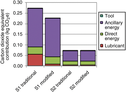
Figure displays the embodied CO2 without the stock to allow better relative comparison of the inputs from the process itself. After the stock contribution (4.20 kg CO2e for traditional or 3.03 kg CO2e for modified), the emissions from the electricity (E A and E D) used are the next largest, particularly from the ancillary processes. However, changing the process parameters (doubling the FD and ST) significantly reduces the impact of the E A used. Finally, changing to an eco-benign lubricant brings the lubricant impact to almost being negligible.
5. Discussion
Table summarises the major numerical findings of this study. It is well known that increasing the batch size for a manufacturing process reduces the time, labour and cost of a part. Considering the hat produced by the SPIF process itself, without labour considerations, the material of the part dominated the cost and CO2 emissions. Using best available data and more eco-benign alternative inputs resulted in a decrease of 28% of CO2 emissions from 4.48 to 3.24 kg CO2e in S1 and from 4.28 to 3.09 kg CO2e in S2 (a $0.062 savings per hat with a carbon price of $50 per tonne CO2). Thus, modifying the inputs to the manufacturing process creates a unique cost and environmental burden reduction opportunity, should the modified inputs have similar or lower costs to the traditional inputs. Comparing the traditional S1 and modified S2 cases demonstrates the power of changing both the inputs and process parameters.
Table 7 Summary of analysis for a hat manufactured with SPIF at two settings.
Concerning the electrical energy used, which is the second largest contributor of CO2 emissions, the E A represented 84% for S1 and 73% for S2 or total energy used. With double the FD and ST increment, S2 was more than three times faster and roughly used three times less energy. This is mainly due to the reduction in E A consumption. In terms of CO2 contribution from E A, the reduction in energy use is related to a reduction in CO2 by 73%. Hence, using alternative parameters and increasing the efficiency of the supporting equipment of the mill are an opportunity to improve the process and further reduce costs. Therefore, further investigation is required to map the relationships between different process settings and energy use for SPIF.
Lubrication is important in SPIF to allow the operation to occur smoothly to attain the required shape and finish. In this study, it was shown that an eco-benign lubricant derived from used cooking oil could be used in SPIF as an alternative to using synthetic or mineral-based gear oils. Qualitatively, there was no observable difference in finish between the two scenarios. In addition, it was observed that the used cooking oil ester flowed better than the 75W-140 used, thus remaining in the path of the tool during SPIF such that less lubricant was used. The resulting reduction in lubricant use along with the lower CO2 EI allowed the lubricant CO2 burden to be almost negligible. Finally, it was also easier to remove (clean) the eco-benign lubricant from the hat. Further studies will be needed to quantify and scientifically understand this observation for a range of lubricants, especially eco-benign and their potential for SPIF.
Limitations of the study include the resolution of the data acquisition system, the EI inputs available and the entire life cycle of the hat not included for the cost and embodied CO2 of the hat. As shown in Figure , the signals did not exactly align in terms of the occurrence of peaks and troughs. This was due to the limited sampling frequency of 1 Hz of the loggers that were used such that an aliasing error is likely introduced. None-the-less, considering the data for three hats per scenario, the standard error was 1–3% in the total energy and 0.03–0.12% for the total time. For the initial study presented, this was reasonable. However, if more accuracy is required in the energy data, especially in the amplitudes of power spikes for peak loading considerations, a higher resolution is recommended that matches the time interval over which power spikes occur. In addition to the aliasing error, there was a slight variability in the baseline standby energy which would impact the overall total energy used since it dominated the E A. This variability could be caused by machine readiness and power supply fluctuations that would vary within a day and between days to name a few. The lack of load conditioning in the supply to the machine would also affect the power factor.
A challenge in the CO2 footprint analysis is to find appropriate EI references for the inputs in the study. Since LCA data tend to supply a static value applicable to a specific location or process, there is an expected error in the absolute LCA CO2 value estimated. Furthermore, lacking EI data for the specific inputs used makes it difficult to make an exact calculation. Thus, using the ‘best reference material’ implies that it is assumed that it is the best freely available data that might most closely represent the EI of the specific input. Regardless of the uncertainty, the power of the analysis presented is in using it for relative comparison with consistent benchmarking. The large impact on the final result was clearly shown by altering the assumed input and its respective EI when considering traditional versus modified inputs. For the analysis, it is assumed that the EIs of literature resources are representative of the inputs in the analysis. The best assumptions are the EIs of the electricity, used cooking oil ester and the aluminium sheet. The Ontario grid EI is used as provided by Environment Canada and the world average data for aluminium sheet are used for the Al-3003 O sheet. The EI of the used cooking oil was provided with the sample. Given that an LCA for the Quaker State 75W-140 could not be found, a Castrol mineral oil EI was used (Nava et al. Citation2010). This assumes that their production and disposal processes yield a similar result and ignore location origin. Similarly, a specific LCA study for SPIF tools was not found such that a milling tool LCA was used where the tool workpiece material was also carbon steel based. While the two tools are obviously different, with the mill tool requiring more intricate machining, coating and overall material removal, it was important to have a tool EI to use on a relative basis with at least a similar material. This study showed the enormous contribution that the workpiece material makes to the overall EI. Again, using the milling EI makes the expressed assumption that both tools are produced, recycled and disposed with similar processes in the same location, noting that majority of tools are manufactured in a few countries (Kara Citation2009). It is possible that a SPIF tool could have a lower EI than a milling tool, especially in this study, where it is custom manufactured and re-grinded in-house which would reduce transportation emissions. Another assumption made with the SPIF tool is that it could last for 1000 hats in the commercial line regardless of the parameters. Tool life and wear prediction models for SPIF tools is lacking in the literature. The tool life impacts the number of parts that can be made and subsequently its contribution to each part in its life cycle. Therefore, it is urged that studies are performed to quantify and estimate the wear characteristics in SPIF tools, given the extensive studies that have been done for other machining and forming operations.
Finally, the entire life cycle environmental impact is not considered for the hat in this study as the SPIF process and CO2 emissions were the main focus. Other areas of investigation in the hat production include the impact of the type of cleaning agents used to remove the lubricant after the SPIF process and adding the cutting, grinding and bending processes to form the brim of the hat. Ultimately, with life cycle impact assessment, the significant environmental burdens in the process should be identified and procedures should be developed to reduce or mitigate them.
Potential future work could include:
| • | defining a comparable process rate metric for SPIF and developing tool life prediction models; | ||||
| • | determining the specific energy requirements of the SPIF process in a comparable metric to traditional machining processes; | ||||
| • | finding the optimum process settings to reduce the energy consumption and embodied CO2 of the SPIF process; | ||||
| • | comparing the SPIF process against traditional forming processes for the same application and product complexity; | ||||
| • | and modifying the SPIF process to improve its effectiveness, e.g. electro-SPIF. | ||||
6. Conclusion
In this paper, an initial analysis of cost, energy and CO2 emissions in producing a unique aluminium hat using SPIF is performed for two scenarios. The S2 involved doubling the FD and step down increment of the S1, as well as using an eco-benign lubricant. The aluminium hat was custom designed and made from Al-3003 O using a custom steel alloy forming a tool on a Bridgeport GX 480 vertical mill. The cost and energy used for the SPIF process without labour were found to be $4.48 and 4580 kJ (1.27 kWh) for S1 and $4.10 and 1420 kJ (0.39 kWh) for S2, respectively. The respective ED required for making the hat was only 16% and 27% of the total required process energy for S1 and S2. Using virgin or traditional EI inputs for the tool, lubricant, workpiece and energy, the embodied CO2 from the process was found to be 4.48 kg CO2e for S1. However, using 33% recycled aluminium, an eco-benign lubricant and a remanufactured tool resulted in an embodied CO2 of 3.24 kg CO2e or a 28% CO2 savings for the same process parameters. Similarly, in S2, the embodied CO2 was found to be 4.28 kg CO2e for traditional inputs and 3.09 kg CO2e for modified inputs. Comparing S1 traditional and S2 modified, there is a reduction in energy use and CO2 by 69% and 31% accordingly. As expected, the stock material dominated the embodied CO2 and cost but the energy consumed was the next highest contributor. Future work will consider optimal parameters for cost, energy and embodied CO2 minimisation.
Acknowledgements
The authors would like to acknowledge the funding support of the NSERC Strategic and Discovery Grants.
References
- Anderberg , S.E. , Kara , S. and Beno , T. 2010 . Impact of energy efficiency on computer numerically controlled machining . Journal of Proceedings of the Institute of Mechanical Engineers , 224 : 531 – 541 .
- Branker, K., 2011. A study of energy, carbon dioxide emissions and economics in machining: milling and single point incremental forming. Master's thesis. Department of Mechanical and Material Engineering, Queen's University, Canada
- Branker , K. , Jeswiet , J. and Kim , I.Y. 2011 . Greenhouse gases emitted in manufacturing a product – a new economic model . CIRP Annals – Manufacturing Technology , 60 : 53 – 56 .
- Crina , R. 2010 . New configurations of the SPIF process – a review . Journal of Engineering Studies and Research , 16 ( 4 ) : 33 – 39 .
- Diarra , D.C. 2010 . Energy consumption and CO2 emissions for manufacturing compressed air system . Transactions of NAMRI/SME 2010 , 38 : 767 – 773 .
- Duflou , J.R. 2008 . Process window enhancement for single point incremental forming through multi-step toolpaths . CIRP Annals – Manufacturing Technology , 57 : 253 – 256 .
- Environment Canada, 2010. Electricity intensity tables. Available from: http://www.ec.gc.ca/ges-ghg/default.asp?lang = En&n = EAF0E96A-1
- Gutowski, T., 2007. The carbon and energy intensity of manufacturing. Fortieth Seminar of CIRP, Keynote Address, 30 May – 1 June, Liverpool University, Liverpool, UK. Available from: http://web.mit.edu/ebm/www/Publications/Carbon%20Intensity%20of%20Manufacturing.pdf
- Gutowski, T., Dahmus, J., and Thiriez, A., 2006. Electrical energy requirements for manufacturing processes. Thirteenth CIRP International Conference on Life Cycle Engineering, 31 May – 2 June, Leuven, CD-ROM. Available from: http://www.mech.kuleuven.be/lce2006/071.pdf
- Hamilton, K.A.S., 2010. Friction and external surface roughness in single point incremental forming: a study of surface friction, contact area and the ‘orange peel’ effect. Master's thesis, Queen's University, Canada
- Hammond , G. and Jones , C. 2011 . Inventory of carbon and energy (ICE V2.0) , Bath, UK : University of Bath . [online]. Available from: http://www.bath.ac.uk/mech-eng/sert/embodied/
- Hussain , G. and Gao , L. 2007 . A novel method to test the thinning limits of sheet metals in negative incremental forming . International Journal of Machine Tools and Manufacture , 47 : 419 – 435 .
- Ingarao , G. , Di Lorenzo , R. and Micari , F. 2011 . Sustainability issues in sheet metal forming processes: an overview . Journal of Cleaner Production , 19 : 337 – 347 .
- Jeswiet , J. 2005 . Asymmetric single point incremental forming of sheet metal . CIRP Annals – Manufacturing Technology , 54 ( 2 ) : 88 – 114 .
- Jeswiet , J. and Nava , P. 2009 . Applying CES to assembly and comparing carbon footprints . International Journal of Sustainable Engineering , 2 ( 4 ) : 232 – 240 .
- Kalpakjian , S. and Schmid , S. 2006 . Manufacturing engineering and technology , 3rd ed. , Reading, MA : Addison-Wesley .
- Kara , H. 2009 . Carbon impact of remanufactured products – end mill cutting tools , 1 – 21 . Aylesbury, UK : Centre for Remanufacturing and Reuse .
- Nava , P. , Jeswiet , J. and Kim , I.Y. 2010 . Calculation of carbon emissions in metal forming manufacturing processes with eco-benign lubrication . Transactions of NAMRI/SME , 38 : 751 – 758 .
- Rauch , M. 2009 . Tool path programming optimization for incremental sheet forming applications . Computer Aided Design , 41 ( 12 ) : 877 – 885 .
