Abstract
This paper reveals comparative experimental analysis of the effect of variation of natural and forced convection heat losses on the performance of prototype parabolic dish water heater with coated and non-coated receivers. With the above-described system, hot water needs in domestic applications can be fulfilled instantly. A parabolic dish collector was used for instant water heating. Design of solar parabolic dish collector consists of truncated cone-shaped helical coiled receiver made up of copper at focal point. Instantaneous efficiency of 63% and 48% has been achieved with coated and non-coated receivers. This prototype has been evaluated for its performance with water flow rate of 0.0076 kg/s during the months of April and May 2010 at Shivaji University, Kolhapur, Maharashtra, India (latitude: 16.42° North, longitude: 74.13° West).
1. Introduction
The concentrated solar thermal energy system is designed and constructed with the conventional parabolic concentrator. The receiver is placed along the line between the centre of the concentrator and the sun. The receiver used is coiled helically with specific design so that all the solar rays concentrated at the centre have received without shadow. Manual tracking has been used during evaluation stage. This allows for effective collection and concentration of the incoming solar irradiation (Duffie and Beckman Citation2006). The concentrator receives approximately 1.064 kW/m2 of total (global) solar insolation (dependent upon time of year), which is concentrated and reflected to the receiver. By concentrating the incoming radiation, the operating temperature of the system increases significantly and subsequently increases the efficiency of the conversion.
2. Literature survey
A simpler batch solar water heater has been investigated by Akuffo and Jackson (Citation1988). This design achieved a maximum temperature of 45°C by 4:30 pm and provided 30°C water at 5:30 am the next day. Daily ambient peak temperatures exceeded 37°C. Hussain Al Madani (Citation2006) studied a batch solar water heater in Bahrain consisting of an evacuated, cylindrical glass tube. Side-by-side testing of prototypes resulted in a maximum temperature difference between the inlet and outlet of the cylindrical batch system of 27.8°C with a maximum efficiency of 41.8%. Nahar (Citation2002, Citation2003) studied a separated storage–collector system. Nahar found that this system can produce 60.6°C water at 4:00 pm and 51.6°C water the next morning. The overall efficiency of this system was determined to be 57%. Tripanagnostopoulos and Souliotis (Citation2006) experimented on optimising an integrated storage–collector batch solar water heater that contained two cylindrical tanks and a compound parabolic concentrator made of aluminium mylar glazed with an iron oxide and black matte absorbing surface.
Zerrouki et al. (Citation2002) studied a similar separated storage–collector system in Algeria. The maximum temperature was observed to be 57°C starting from an initial temperature of 17°C at 7:00 am.
3. Description of system used
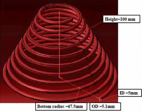
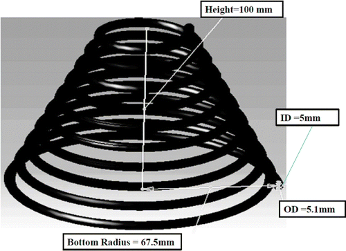
System consists of parabolic dish of 1.4 m diameter. It has been made of anodised aluminium mirrors and supported with locally manufactured steel stand. At focus, truncated cone-shaped helical coil made up of copper is fitted and it has been coated with nickel chrome. Inner and outer diameters of hollow receiver coils are 5.0 and 5.1 mm, respectively. The spacing between two coils is 5 mm and angle of helix is 5°. Inlet and outlet pipes made of high temperature and pressure poly vinyl chloride (PVC) are attached to coil. Inlet water flow has been controlled by using inlet valve, and hot water at outlet is collected in insulated tank.
Flow of water has been kept as 0.0076 Kg/s. Thermocouples of K types have been used to measure the temperatures of inlet and outlet water, receiver surface temperature. Wind speed and solar radiation has been measured with anemometer and pyranometer respectively. This prototype has been evaluated for its performance during the months of April and May 2010 under standard test conditions (MNRE and BIS draft test procedure Citation2006, Citation2009). Tables and show the parameters used for experimentation.
Table 1 Parameters used for experimentation.
Table 2 Nomenclature and subscripts.
4. Experimental procedure
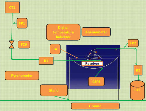
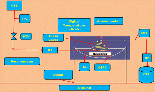
Test set-up consists of a cavity receiver supported by support. The receiver has been kept vertically upright with respect to the horizontal. The cold water circulated in the receiver is supplied from a water tank of 100 litre capacity. The working fluid has been circulated through the receiver tubes by siphon, i.e. natural circulation. A rotameter at inlet measures the mass flow rate of cold water entering the receiver. The cold water has been circulated at constant inlet temperature through the receiver. The temperatures of the fluid in the tube at four locations (including the outlet) are measured using K-type thermocouples. The flow has been kept constant for the complete period of an experimental run on a given day. The system has been operated under open-loop condition as the water exiting from the receiver is not circulated back to the inlet cold water supply tank. The hot water has been stored in an insulated tank and kept near the outlet. The wind speed measurements have been taken at a fixed location near the parabolic dish collector plane. The wind blows in the direction normal to the receiver and also the direction of the wind is parallel to the receiver. The schematic of the experimental set-up witch has been used for instant water heating which is shown in Figure .
The working fluid used during experiment is cold water and inlet temperatures on the experimental day vary between 23°C and 27°C. For each test, the inlet fluid temperature has been measured by using thermocouple. The working fluid enters and exits the receiver as shown in Figure . The working fluid enters through inlet at the bottom portion of the receiver and flows through the helically coiled receiver and leaves receiver at the uppermost portion. The solar radiations, receiver surface temperatures and the fluid temperatures are measured at intervals of half-hour, and the experiment has been continued till the solar radiation is available at sufficient intensity. The thermal losses are estimated at steady state (Figure ). Helical coil as shown in Figures and representing the receivers without coating and with coating of black nickel chrome paint. For the experiments with black-coated receiver, the region outside the cavity has been surrounded by a downward-facing cylindrical glass enclosure.
5. Calculations
5.1 Terrestrial solar radiation
Ground level radiation can be estimated using Hottel's clear sky model for urban visibility 5 km at Kolhapur
5.2 Geometric concentration ratio for designed collector
Geometric concentration ratio for designed collector is given by (Duffie and Beckman Citation2006)
5.3 Calculation of heat losses from the receiver
Thermal losses from solar open cavity receivers include convective and radiative losses to air.
For focal plane, i.e. cavity receiver overall heat loss is given by (Duffie and Beckman Citation2006)
To estimate natural convective heat loss, following correlation developed by Prakash et al. (Citation2009) is used
Forced convection loss coefficient is given by the following equation. This equation is developed by Ma (Gordon and Rabl Citation1982, Fraser Citation2008)
5.4 Experimental data
See Tables and .
Table 3 Experimental measurements and calculations for non-coated receiver at mass flow rate 0.0076 kg/s.
Table 4 Experimental measurements and calculations for coated receiver at mass flow rate 0.0076 kg/s.
6. Results and discussion
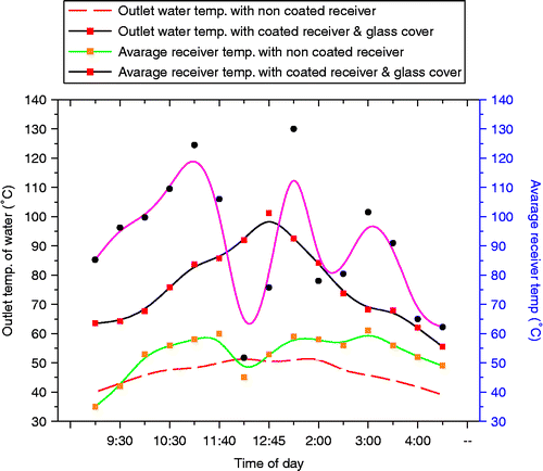
Figure indicates that receiver temperature increases rapidly as the solar radiation on collector increases. It, in turn, increases the outlet water temperature. Also it has been observed that as the atmospheric temperature rises there is rise in inlet water temperature. The rise of temperature of outlet water is also affected by wind velocity at that instant. It has been observed that there is average rise of 12% and 16% in outlet water temperature and average receiver temperature, respectively, with coated receiver and glass cover as compared with non-coated receiver. Maximum outlet water temperature of 61°C and average receiver temperature of 124°C have been achieved with the coated receiver and glass cover.
Figure (A–D) clarifies that as wind velocity at instant increases, there is a rapid rise in convective heat loss coefficients of both types, viz. natural and convective. It has been seen that forced convective heat loss coefficient has significant share in total convective heat loss coefficient. Comparatively for non-coated and coated receivers, for variation of 2% of wind velocity, total convective heat loss coefficient also varies by 2%. Also for same variation of wind velocity, forced convective heat loss coefficient varies by 3% and natural convective heat loss coefficient varies by 0.32% only. This proves that forced convective heat loss coefficient has significant share in total convective heat loss coefficient.
Figure 6 (A) Variation of total convective heat loss coefficient with wind velocity throughout the day. (B) Variation of natural, forced and total convective coefficient for non-coated receiver throughout the day. (C) Variation of natural, forced and total convective coefficient for coated receiver and glass cover throughout the day. (D) Comparison of variation of total convective coefficient for non-coated and coated receivers throughout the day.
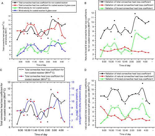
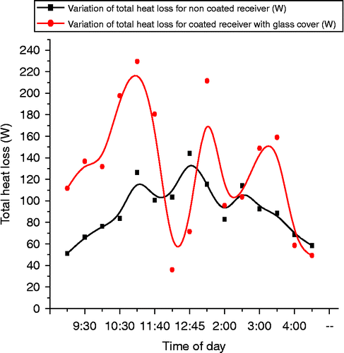
Figure explores variation of total heat loss. Heat lost by receiver adversely affects the performance of collector. The reason is that as overall heat loss coefficient increases, total heat loss increases and reduces collector efficiency significantly. Comparatively for non-coated and coated receivers, it has been observed that average variation in total convective heat loss is 28% and maximum variation is 37%.
From variation plotted in Figure , it has been observed that though the beam radiation on collector is more and average receiver temperature increases, but due to higher wind speed, there are increased forced convective losses through the receiver and it affects adversely the performance of parabolic dish collector and total system. It has been observed that for coated and non-coated receivers, for average variation of total convective heat loss coefficient by 2%, there is variation of 13% in useful heat gain by water. Water gains 13% more heat with coated receiver and glass cover as compared to non-coated receiver. It has also been observed that forced convective heat loss have higher contribution in reducing the useful heat gain by receivers as compared to natural convective heat losses.
Figure 8 Variation of total convective heat loss coefficient with useful heat gain by water throughout the day.
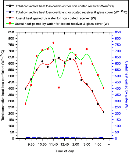
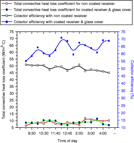
Figure presents variation of collector efficiency with convective heat losses. It has been observed that forced convective heat loss has higher contribution in reducing the efficiency of collector as compared to natural convective heat losses. Efficiency of collector drastically drops at higher wind speed because of higher convective heat losses. For average variation of 3% in forced convective heat loss coefficient as compared with average variation of 0.32% in natural convective heat loss coefficient, there is variation of 23% in collector efficiency for coated and non-coated receivers. Collector efficiency of 63% to 48% has been achieved with coated receiver and non-coated receiver, respectively.
7. Conclusion
An experimental and numerical study of parabolic solar dish collector water heater with coated and non-coated receivers has been conducted under Kolhapur climatic conditions. General comparison between the parabolic solar dish collector water heater and common models such as flat plate and evacuated tube collectors demonstrated that parabolic solar dish collector water heater is a good alternative for flat plate and evacuated tube water heaters and could be applied effectively. Therefore, the developed model can be considered for designing commercial parabolic solar dish collector water heater. Proposed system is aimed at saving conventional energy sources and environment too. Such objectives are important parts towards the development of self-sufficient sustainable homes in rural as well as urban areas of India. Measure findings from experimentation have been listed. In future, this type of system can be used for heating boiler feedwater, laundry applications and other steam generation applications.
| 1. | With the above-described system, collector efficiency of 63–48% has been achieved with coated receiver and non-coated receiver, respectively. | ||||
| 2. | There is average rise of 12% and 16% in outlet water temperature and average receiver temperature, respectively, with coated receiver and glass cover as compared to non-coated receiver. | ||||
| 3. | This has been proved that forced convective heat loss coefficient has significant share in total convective heat loss coefficient. | ||||
| 4. | Forced convective heat loss coefficient varies by 3% and natural convective heat loss coefficient varies by 0.32% only. | ||||
| 5. | Comparatively for non-coated and coated receivers, it has been observed that average variation in total convective heat loss is 28%. | ||||
| 6. | Water gains 13% more heat with coated receiver and glass cover as compared with non-coated receiver. | ||||
Acknowledgement
The authors would like to thank the Department of Technology for providing lab support to this research work.
References
- Akuffo , F.O. and Jackson , E.A. 1988 . Simulation studies on a compact solar water heater in the tropics . Solar and Wind Technology , 5 ( 6 ) : 229 – 237 .
- Duffie , J. and Beckman , W. 2006 . Solar engineering of thermal processes , New York : Wiley .
- Fraser, P.R., 2008. Stirling Dish system performance prediction model. Thesis (M.S. Mechanical Engineering). University of Wisconsin-Madison
- Gordon , J.M. and Rabl , A. 1982 . Design, analysis and optimization of solar industrial process heat plants without storage . Solar Energy , 28 ( 6 ) : 519 – 530 .
- Hussain , Al Maidani . 2006 . The performance of a cylindrical solar water heater . Renewable Energy , 31 ( 15 ) : 1751 – 1763 .
- Ministry of Renewable Energy (MNRE) and Bureau of Indian Standards (BIS) . 2006 . “ Draft test procedure for solar cooker – paraboloid concentrator type ” .
- Ministry of Renewable Energy (MNRE) and Bureau of Indian Standards (BIS) . 2009 . “ Draft test procedure for thermo siphon-type domestic solar hot water systems ” .
- Nahar , N.M. 2002 . Capital cost and economic viability of thermosyphonic solar water heaters manufactured from alternate materials in India . Renewable Energy , 26 ( 4 ) : 623 – 635 .
- Nahar , N.M. 2003 . Year round performance and potential of a natural circulation type of solar water heater in India . Energy and Buildings , 35 ( 3 ) : 239 – 247 .
- Prakash , M. , Kedare , S.B. and Nayak , J.K. 2009 . Investigations on heat losses from a solar cavity receiver . Solar Energy , 83 ( 12 ) : 157 – 170 .
- Tripanagnostopoulos , Y. and Souliotis , M. 2006 . ICS solar systems with two water tanks . Renewable Energy , 31 ( 15 ) : 1698 – 1717 .
- Zerrouki , A. , Boumedien , A. and Bouhadef , K. 2002 . The natural circulation solar water heater model with linear temperature distribution . Renewable Energy , 26 ( 4 ) : 549 – 559 .
