Abstract
In this paper, performance of a solar hybrid adsorption refrigeration (AR) system is investigated experimentally. Such a system was built and tested under the conditions at National Institute of Technology Calicut, Kerala, India. The hybrid system has been designed for heating 50 l of water from 25 to 90°C as well as cooling 10 l of water from 25 to 10°C. The experimental results demonstrate that the refrigerator has a cooling capacity of 47–78 W with a cycle coefficient of performance (COP) of 0.19 and maximum possible COP of 0.45. In exergy analysis of the system, the irreversibility and exergetic efficiency of each component of the system have been calculated. The exergy analysis reveals that the main source of irreversibility is the adsorbent bed of the AR system, emphasising that the input heat energy is not utilised efficiently due to material constraints. The exergetic efficiencies of condenser, expansion device, evaporator and adsorbent bed are found as 42.3%, 79.8%, 54.7% and 11%, respectively.
| Nomenclature | ||
| C | = | concentration ratio |
| Cp | = | specific heat (kJ kg− 1 K− 1) |
| COP | = | coefficient of performance |
| D | = | diameter (m) |
| E | = | energy (kJ) |
| h | = | enthalpy (kJ) |
| I | = | intensity of solar radiation (W/m2) |
| = | mass flow rate (kg/s) | |
| p | = | pressure (Pa) |
| T | = | temperature (K) |
| = | rate of heat transfer (kW) | |
| = | rate of work transfer (kW) | |
| Subscripts | = | |
| 1, 2, 3, 4 | = | state points in the diagram |
| ads | = | adsorption/adsorbent bed |
| des | = | desorption |
| c | = | cooling water |
| cond | = | condenser |
| expa | = | expansion device |
| evap | = | evaporator |
| con | = | condensation |
| eva | = | evaporation |
| i/in | = | inlet |
| o/out | = | outlet |
| f | = | fluid |
| r | = | refrigerant |
| Greek symbols | = | |
| = | exergy (kJ) | |
| = | rate of exergy (kW) | |
| η | = | efficiency |
Introduction
The interest in adsorption refrigeration (AR) systems started to increase firstly due to the oil crisis in the 1970s which led to a concern about the energy shortage, and then in 1990s because of ecological problems related to the use of Chloro fluro carbons (CFCs) and hydro chloro fluro carbons (HCFCs) as the refrigerants. Furthermore, with the increase in worldwide energy consumption, it is becoming even more urgent to find the ways of using energy resources efficiently as possible. Thus, machines such as AR machines that can be driven by low-grade energy sources such as solar energy and industrial wastes can be an interesting alternative for a wiser energy management (Sumathy, Yeung, and Yong Citation2003). The major attraction of solar AR is that its working fluids satisfy the Montreal Protocol on ozone layer depletion and the Kyoto Protocol on global warming. The consumption of low-grade energy by the adsorption units does not possess any problems of emission of greenhouse gases. Solar power-based refrigerator is simple and is adaptable for small, medium or large systems. The solar AR system has been developed to be used in hot regions mainly where no electricity is available.
In recent years, a number of experimental and theoretical studies on the solar AR system have been reported. Sumathy and Li (Citation1999) investigated experimentally a solar-powered adsorption system using activated carbon–methanol pair. The system has a coefficient performance (COP) of about 0.1–0.12 for flat plate collector having an exposed area of 0.92 m2. Pons and Guilleminot (Citation1986) conducted similar experiments with activated carbon–methanol pair in a solar-powered adsorption chiller. The COP of the system reported was 0.12. Dawoud (Citation2007) made a hybrid solar-assisted adsorption cooling unit for vaccine storage. Ghali, Othmani, and Gaddar (Citation2008) made a desiccant wheel to study the hourly performance of the hybrid system when used a typical auditorium in air conditioning. They also carried out a comparative study between the conventional air-conditioning systems with the hybrid system under the conditions of city of Beirut.
Nowadays, a more generic approach based on the second law is used for the analysis of thermal energy systems. Exergy analysis has become an integral part of the thermodynamic assessment of a system. The conventional energy analysis does not give the qualitative assessment of the various losses occurring in the system components (Haught Citation1984). The second law analysis is used to get a clear picture of various losses quantitatively as well as qualitatively (Bejan and Chelghoum Citation1985). Xiong, Dai, and Wang (Citation2010) carried out exergy analysis of a liquid desiccant dehumidification system. The exergetic efficiencies of each components of the system are calculated. The exergetic efficiency of the base system was obtained as 6.3%. Yang et al. (Citation2005) carried out exergy analysis for transcritical carbon dioxide refrigeration cycle with an expander. They compared the performance of refrigeration cycle with throttling valve and an expander. Gebreslassie et al. (Citation2010) conducted a study on exergy analysis of water–LiBr absorption refrigeration system. Esen et al. (Citation2007) conducted a study on energetic and exergetic efficiencies of ground-coupled heat pump system as a function of depth trenches for heating season. Tiwari, Dimri, and Chel (Citation2009) carried out exergy analysis of active and passive solar distillation units. The second law analysis of double effect absorption chiller has been carried out by Ben Ezzine et al. (Citation2004) to identify the main sources of irreversibility. The solar-assisted heat pump system has been analysed by second law analysis of thermodynamics for determining the second law efficiency of the system components (Dikici and Akbulut Citation2008).
The theoretical and experimental study of the solar AR system is presented here. The performance parameters namely cooling COP, specific cooling power (SCP) and mass of refrigerant desorbed are obtained from the experimental results. The irreversibility and exergetic efficiency of each component are obtained from the experimental data.
System description and experimental procedure
The experimental set-up is located in the Solar Energy Laboratory at National Institute of Technology Calicut, Kerala, India. The solar AR system is tested under the meteorological conditions of Calicut (latitude of 11.15°N, longitude of 75.49°E) during April 2011.
System description
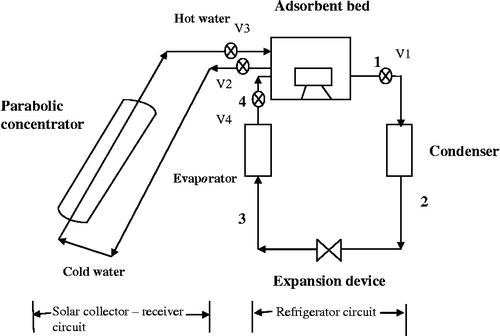
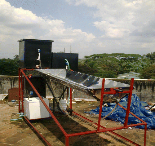
The system is designed to produce chilled water utilising solar energy. The system is divided into two circuits, namely refrigerator circuit and solar collector circuit. The solar collector–receiver circuit consists of a parabolic solar concentrator and a receiver. The refrigerator circuit of the solar-assisted AR system consists of an adsorbent bed, condenser, expansion device (capillary tube) and evaporator as shown in Figure and its photograph is shown in Figure . The specifications of components used in the system are given in Table .
Table 1 Specifications of the main components of the solar AR system.
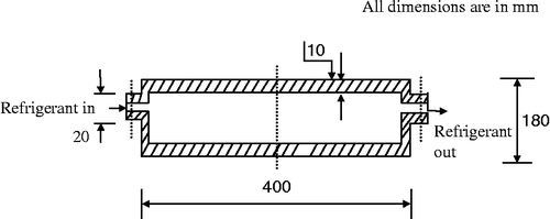
Function of solar concentrator is to tap solar energy and this may be transferred to the water passing through the absorber tube. Parabolic solar concentrator of area 3 m2 made of stainless steel is used. The absorber consists of two concentric tubes. Inner tube is made of copper and outer is glass. This is fixed along the focal line of the parabolic concentrator. The adsorbent bed made of stainless steel is used for the study. The adsorbent bed is designed by estimating the amount of activated carbon required to adsorb the quantity of refrigerant to be charged into the bed. The amount of refrigerant to meet the cooling demands is arrived at from the cooling load and the enthalpy change of the refrigerant in the evaporator for a pair of condensing and evaporating temperatures. The inlet and outlet for the refrigerant were made on the two opposite faces of the adsorbent box. A vacuum gauge and thermocouple are fixed in the bed for measuring the pressure and adsorbent bed temperature, respectively.
The condenser is of shell and coil (material:copper) type and is water cooled. The inlet of the condenser is connected to the adsorbent bed and the refrigerant leaves to the capillary tube. The evaporator coil of 150 W capacity made of copper is placed inside the refrigerator box. The refrigerator box is made up of mild steel and is insulated with polyurethane foam with a thickness of 2.5 cm.
Working pair used
Methanol of 99.98% purity is used as a refrigerant in this study and is supplied by Methanex Corporation. All the properties of methanol used in the paper are taken from REFPROP software. The activated carbon (grade 4 × 8), which is supplied by Indo-German Private Ltd (Kochi, India) of particle diameter 0.25 mm is used.
Instrumentation
Calibrated thermocouples are fixed in the refrigerant line at the adsorbent bed inlet and outlet, condenser outlet, expansion device outlet and on the top of the absorber tube of the solar collector to measure the temperature at important locations in the system. Another thermocouple is inserted to the adsorbent bed to measure the adsorbent bed temperature during the processes. Four pressure gauges of accuracy ± 2% are fixed at the inlet and outlet of the adsorbent bed and expansion device inlet and outlet, for measuring the pressure of refrigerant entering into the adsorbent bed, discharge pressure, condenser outlet pressure and pressure of the refrigerant after expansion, respectively. A digital pyranometer with an accuracy of ± 5% W/m2 is placed near to the solar collector to measure the instantaneous solar intensity. All the measured data are used for the exergy analysis of the system.
Experimental procedure
The system is tested for leaks with pressurised nitrogen gas. Furthermore, the time-dependent leaks are also cleared off by checking the drop in pressure of the system for over 24 h. After the pressure and evacuation tests, the system is charged with 1000 g of methanol refrigerant. The experiments are conducted from 8 am to 5 pm. In the beginning, keeping valves V1 and V4 closed, the water tank is filled with sufficient quantity of water.
Water in the tank gets heated up due to solar radiation received on the solar concentrator. When the hot water is circulated around the adsorbent bed, the temperature in the adsorbent bed increases. This causes the vapour pressure of the adsorbed refrigerant to reach up to the condensing pressure. The exit valve V1 should be opened (at 1 pm), when the refrigerant temperature reaches to desorption temperature. At this time, the methanol vapour adsorbed in the activated carbon will be released. The desorbed refrigerant enters the condenser, after being condensed by water, methanol flows into the expansion device. The high-pressure liquid refrigerant is expanded through the expansion device to the evaporator pressure. The low-pressure liquid refrigerant then enters the evaporator where it evaporates by absorbing the latent heat of evaporation. By the evening, the hot water from the tank should be drained off and is refilled with cold water. The temperature of the adsorbent bed reduces rapidly and the pressure in the adsorber drops below the evaporator pressure. The experiments are repeated for different evaporator loads. During experimentation, temperature and pressure at typical locations of the solar AR system are recorded.
Adsorbent bed
The adsorbent bed is as shown in Figure . The bed is made of stainless steel. The dimensions of the beds are 400 mm × 400 mm × 180 mm. Activated carbon is selected as adsorbent material and methanol as the refrigerant (activated carbon–methanol pair) for the system. All the properties of refrigerant used in this study are taken from REFPROP software. The thermophysical properties of activated carbon used are shown in Table .
Table 2 The thermophysical properties of activated carbon.
Uncertainty analysis
Uncertainties in the experiments can arise from the selection, condition and calibration of the instruments, environment, observation and test planning. A more precise method of estimating uncertainty has been presented by Holman (Citation2009). The method is based on a careful specification of uncertainties in the various primary experimental measurements. These measurements are then used to calculate some desired results of the experiments. In this study, the pressure, temperature and solar insolation are measured by using the instruments. The method of calculating uncertainty of components in energy-based system is given by Mohanraj, Jayaraj, and Muraleedharan (Citation2011). The total uncertainty of the various calculated parameters is shown in Table , whereas the calculation procedure is given in Appendix.
Table 3 Uncertainty of performance parameters.
Thermodynamic analysis
The thermodynamic modelling based on the first and second law of thermodynamics has been used to study the energy and exergy performance of AR system working with activated carbon and methanol. The energy and exergy balance equations are used to find out the heat input, irreversibility and energy and exergetic efficiencies. For the thermodynamic analysis, the system is being considered as comprising of two circuits namely collector–receiver circuit and refrigerator circuit. The collector–receiver sub-system consists of a parabolic solar concentrator and an absorber tube made of copper. The refrigerator sub-system consists of a condenser, expansion device, evaporator and adsorbent bed.
Assumptions
The following assumptions are made for the first and second law analyses of the AR system.
Potential, kinetic and chemical effects are neglected.
Mass flow rate of the refrigerant at any point in the system is constant.
All the processes occur at a steady state.
The process in the expansion device is isenthalpic.
Losses in the ducts and valves are neglected.
First law analysis
The general energy balance equation for a component is given by
Energy balance for the solar AR system using Equations (1) and (2)
The energy balance for the solar hybrid AR system is shown in Tables and .
Table 4 Collector–receiver circuit.
Table 5 Refrigerator circuit.
Performance parameters of the solar hybrid AR system
Cycle COP
Cycle COP is defined as the ratio of cooling effect to the total energy required for desired cooling effect:
The total energy input to the system is given bySpecific cooling power
SCP indicates the size of the system as it measures the cooling output per unit mass of adsorbent per unit time. Higher SCP values indicate the compactness of the system:
Solar cooling COP
Since the system is solar powered, the solar COP is also defined. The solar COP of the adsorption system is given by Huilong et al. (2010) as the ratio of cooling effect to the net solar energy input:
Desorbed mass
The mass of refrigerant desorbed is given by
The total mass of the refrigerant charged into the system:Final mass of the refrigerant:
The concentration of the adsorbate in adsorbent can be determined from the Dubinin–Astakhov (D–A) relationship equation (Anyanwu and Ogueke Citation2005):where W0 is the maximum adsorption capacity, D and n are the structural constants of adsorbent and Ps is the saturation pressure of methanol at temperature T.Exergetic efficiency
Heating COP
For the hybrid system, the solar heating COP is also defined. This is defined as the ratio of heat gain by water to the net solar energy input:
Maximum possible COP
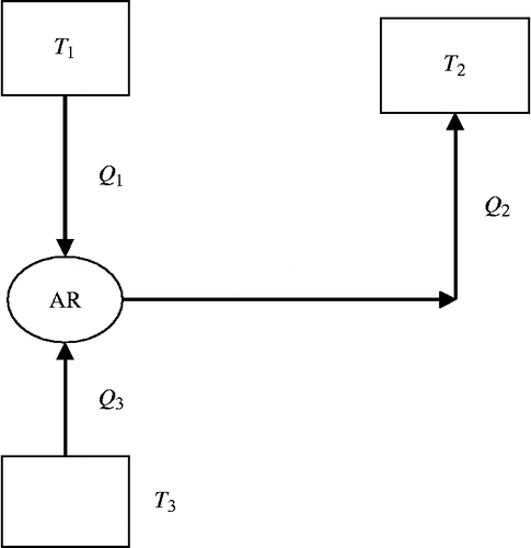
The AR system is a heat-operated machine. Figure shows an equivalent thermodynamic cycle of the solar hybrid AR system. The thermodynamic cycle can be considered as comprising of a heat engine cycle and a refrigeration cycle. Here heat engine cycle operates between the source temperature T1 (Tdes) and the temperature of heat rejection T2 (Tcond). The refrigeration cycle operates between the refrigeration temperature T3 (Tevap) and heat rejection temperature T2.
COP of the machine is the maximum if the heat engine and refrigerator have the maximum performance:
If
Second law analysis
The general exergy balance equation can be written as follows:
The exergy balance equation in rate form can be written as
Results and discussion
Experimental results
Hourly variation of solar radiation with time
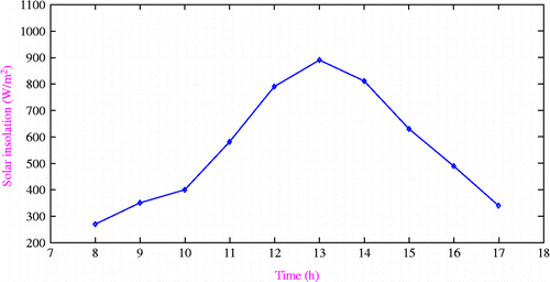
Figure shows the variation of solar insolation with time of day. It is found that the maximum solar insolation is 890 W/m2 which occurs at 13.00 h.
Average values of performance parameters of the AR system
Table shows the average values of performance parameters of the solar hybrid AR system.
Table 6 The average values of performance parameters of the solar hybrid AR system.
A comparison between the study reported in this paper and the other studies from literature is shown in Table for the same heat source and working pairs. From this comparison, it can be concluded that the COP value obtained in this study is in good agreement with the COP values obtained by the different investigators.
Table 7 Comparison of several typical studies by using activated carbon–methanol working pairs.
Variation of experimental COP with chilled water temperature
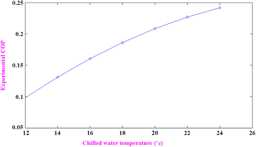
The variation of actual COP of the system with chilled water temperature is shown in Figure . It shows an increase in COP of the system with an increase in chilled water temperature. The reason is that refrigeration effect per kilogram of refrigerant increases as the exit enthalpy of the refrigerant is more if the evaporator is operated at high loads. The experimental COP varies between 0.102 and 0.24 at an average value of 0.196 with the increase in evaporator loads between 47 and 78 W.
Comparison of COPs with chilled water temperature
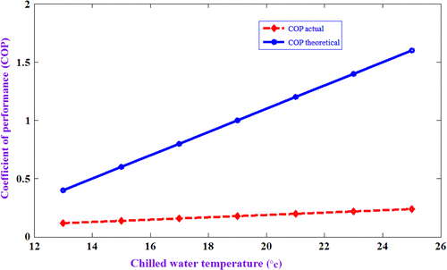
Figure shows variation of actual COP and theoretical COP with chilled water temperature. The experimental COP increases marginally, but the theoretical COP increases drastically with an increase in chilled water temperature. The significant deviation between theoretical and actual COPs is observed. The theoretical COP is calculated by taking the ratio of difference in enthalpy at inlet and outlet of the evaporator (h4–h3) and adsorbent bed (h1–h4). The properties of refrigerant are taken from REFPROP software for the corresponding pressure and temperatures. The actual COP is calculated from the actual cooling effect produced and the heat input to the system from Equations 34(5).
Variation of exergetic efficiency and cycle COP with the heat source temperature
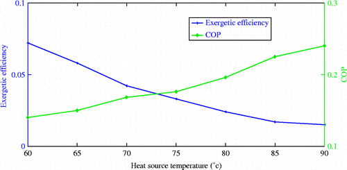
From Figure , it is clear that the COP value increases with increase in heat source temperature, but exergetic efficiency shows a different behaviour. The COP value depends upon the mass of adsorbate generated which in turn is a function of heat source temperature. The heat source temperature should be optimum as the amount of refrigerate generated depends not only on a function of heat source temperature but also on the adsorption characteristics of the activated carbon and chemical properties of the refrigerant. Since the adsorption takes place at the exothermic conditions, cooling of adsorbent bed is very important and the adsorbent temperature is close to the ambient conditions. This will increase the quantity of refrigerant adsorbed in the adsorbent matrix. The very high source temperature will delay the time to cool the adsorbent bed to the adsorption temperature and hence reduces the refrigeration time. The left-hand side of point of intersection of both the curves reveals the high exergetic efficiency with the low COP values. That means the system utilises high percentage of the heat supplied for useful cooling. The right-hand side of the point shows lower exergetic efficiency and higher COP values. At higher source temperatures, the percentage of applied heat utilised for useful cooling is low. A large amount of heat is utilised for the wasteful heating of adsorbent and adsorbent bed material.
Variation of desorbed refrigerant with desorption time
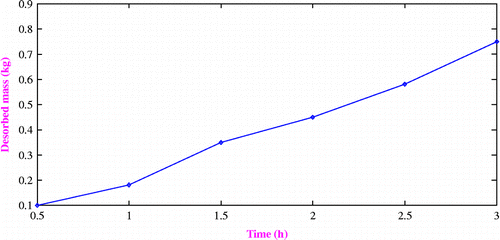
Variation in the desorbed mass of refrigerant with time is illustrated in Figure . It can be seen from the graph that activated carbon may desorb 0.72 kg of refrigerant methanol after the complete desorption time from the total 1.0 kg of methanol charged initially. This is due to the insufficient solar energy available to maintain the required desorption temperature at all time.
Variation of water and adsorbent temperature with heating time
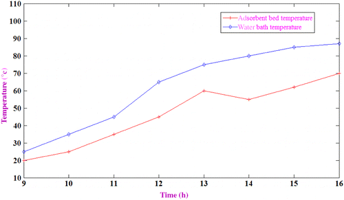
Figure shows the variation of water bath temperature and adsorbent temperature with time. It is observed that after 4 h of heating, there is a temperature drop in the absorbent bed, which represents the start of desorption by opening desorption valve. The desorption process needs heat input, so if the heat input is not enough, then the adsorbent temperature will drop. The exit valve of adsorbent bed is opened at 13.00 h.
Variation of pressure in the adsorbent bed with time
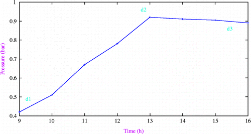
Figure shows typical pressure variations in adsorbent bed during heating and desorption phases. The first-order behaviour (d1–d2) is a typical heating of the adsorbent bed. The dip in pressure at d2 is due to the opening of exit valve of the adsorbent bed driving the flow out of the adsorbent bed.
Thermodynamic analysis results
The energy analysis results are given in Table . It is found from Table that the highest energy loss takes place in the collector–receiver circuit through the collector. Although energy loss in the refrigerator circuit is significant, the percentage of energy loss in the collector–receiver circuit is higher than that of the refrigerator circuit. The first law efficiency of solar concentrator is obtained as 34.5%.
Table 8 Energy balance for the complete system.
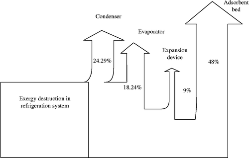
The irreversibility caused by entropy production has been calculated component wise and it is shown in Table . The percentage of exergy loss in the refrigerator circuit is shown in the Grassmann (exergy flow) diagram as shown in Figure . The causes of exergy losses in the vapour AR system include the adsorbent bed, condenser, expansion device and evaporator. As shown in Table , the exergy losses in the evaporator and expansion device have the lowest values. The exergy loss in the expansion device is about 0.0128 kW, in the evaporator it is 0.0425 kW and in the condenser it is 0.048 kW. The results indicate that the irreversibility in the adsorbent bed is higher due to the large amount of energy spent for heating the adsorbent and the bed material. The exergy loss in the adsorbent bed is quantified as 0.109 kW.
Table 9 Second law analysis of refrigerator circuit.
The second law efficiency for each component is calculated by using Equation (11). The second law efficiency of adsorbent bed is found to be 11.02%. The second law analysis of collector–receiver circuit is shown in Table .
Table 10 Second law analysis of collector–receiver circuit.
The result shows that the entropy generation or irreversibility associated with the adsorbent bed is on higher side and this is why the exergetic efficiency is very low. This implies that the percentage of applied heat energy used in producing the useful compression is very low. The rest of the heat energy is used in wasteful heating of adsorbent and metal components to high generator temperature. This implies that the heat transfer characteristics of adsorbent play an important role in the design of adsorbent bed in an AR system. The thermal conductivity of the adsorbent and adsorbate, the geometry of contact between the particles and porosity are the parameters that need to be taken into account. In order to improve the heat transfer characteristics of the adsorbent, the use of coated or consolidated adsorbent is proposed. The use of composite adsorbent block and monolithic carbon can improve the thermal conductivity and density of the bed. Wu et al. (Citation2009) evaluated the method for improvement of heat transfer characteristics of composite adsorbents. They conducted study on heat and mass transfer characteristics of composite bricks consisting of silica gel and copper nano powder.
Conclusions
This work deals with the type of AR system which uses solar energy as input. An experimental system has been installed and tested for analysing its performance. The energy and exergy balance equations have been derived using the first and second law of thermodynamics. The exergy loss and exergetic efficiency of each component of the system have also been estimated. The main conclusions derived from this study are given below:
The hybrid solar-assisted AR system proved the suggested idea of combined heating and cooling cycle. It was found that the system is capable of heating 40 kg of water from 30 to 85°C and cooling 10 kg of water from 30 to 13.4°C. The experimental results show that the refrigerator has a cooling capacity between 47 and 78 W.
The COP value is obtained as 0.19. The COP is fairly close to those reported by other investigators.
The irreversibilities have been calculated component wise. It is shown that irreversibilities associated with the adsorbent bed of the refrigerator circuit and collector in the collector–receiver circuit are found to be on higher side.
The operational parameters must be optimised to reduce the exergy destruction leading to an improved exergetic efficiency. The materials used for solar concentrator and adsorbent bed may be selected according to the thermophysical properties which enhance exergetic efficiency.
The exergetic efficiency of the system is determined for different evaporator loads, and the effect of heat source temperature on exergetic efficiency and COP of the system is studied.
REFERENCES
- Anyanwu, E. E., and N. V.Ogueke. 2005. “Thermodynamic Design Procedure for Solid Adsorption Solar Refrigerator.” Renewable Energy30: 81–96.
- Bejan, A., and D. E.Chelghoum. 1985. “Second Law Analysis of Solar Collector with Energy Storage Capacity.” ASME Journal of Solar Energy Engineering1107: 244–251.
- Ben Ezzine, N., M.Barhoumi, K. H.Mejbri, S.Chembi, and A.Bellagi. 2004. “Solar Cooling with the Absorption Principle: First and Second Law Analysis of Ammonia–Water Double Generator Absorption Chiller.” Desalination168: 137–144.
- Boubakri, A.2003. “A New Conception of an Adsorptive Solar Powered Adsorption Ice Maker.” Renewable Energy28: 831–842.
- Butcher, F., P. H.Dind, and M.Pons. 2003. “An Experimental Solar Powered Adsorptive Refrigeration Tested at Burkina-Faso.” International Journal of Refrigeration26: 79–86.
- Dawoud, B.2007. “A Hybrid Solar Assisted Adsorption Cooling Unit for Vaccine Storage.” Renewable Energy32: 947–964.
- Dikici, A., and A.Akbulut. 2008. “Performance Characteristics and Energy–Exergy Analysis of Solar Assisted Heat Pump System.” Building and Environment43: 1961–1972.
- Esen, H., M.Inalli, M.Esen, and K.Pihtili. 2007. “Energy and Exergy Analysis of a Ground-Coupled Heat Pump System with Two Horizontal Ground Heat Exchangers.” Building and Environment42 (10): 3606–3615.
- Gebreslassiea, B. H., M.Medrano, and D.Boer. 2010. “Exergy Analysis of Multi-effect Water LiBr Absorption Systems: From Half to Triple Effect.” Renewable energy35 (8): 1773–1782.
- Ghali, K., M.Othmani, and N.Gaddar. 2008. “Energy Consumption and Feasibility Study of a Hybrid Desiccant Dehumidification Air-Conditioning System in Beirut.” International Journal of Green Energy5: 360–372.
- Haught, A. P.1984. “Physical Consideration of Solar Energy Conversion.” ASME Journal of Solar Energy Engineering106: 3–15.
- Holman, J. P.2009. Experimental Methods for Engineers. 7th ed.New Delhi: Tata McGraw-Hill Publishing Company Limited.
- Huilong, L., R. Z.Wang, and Y. J.Dai. 2010. “Optimum Matching of Heat Source Temperature to a Solar Adsorption Air-Conditioning System for Maximum Solar Cooling Coefficient of Performance.” International Journal of Green Energy7: 91–102.
- Leite, A. P. F., and M.Daguenet. 2000. “Performance of a New Solid Adsorption Icemaker with Solar Energy Regeneration.” Energy Conversion Management42: 1625–1647.
- Mohanraj, M., S.Jayaraj, and C.Muraleedharan. 2011. “Modeling of a Direct Expansion Solar Assisted Heat Pump Using Artificial Neural Networks.” International Journal of Green Energy5: 520–532.
- Pons, M., and J. J.Guilleminot. 1986. “Design of an Experimental Solar Powered Solid Adsorption Ice Maker.” ASME Journal of Solar Energy108: 332–337.
- Sumathy, K., and Z. F.Li. 1999. “Experiments with Solar Powered Adsorption Ice Maker.” Renewable Energy16: 704–707.
- Sumathy, K., K. H.Yeung, and L.Yong. 2003. “Technology Development in the Solar Adsorption Refrigeration Systems.” Progress in Energy and Combustion Science29: 301–327.
- Tiwari, G. N., V.Dimri, and A.Chel. 2009. “Parametric Study of an Active and Passive Solar Distillation System: Energy and Exergy Analysis.” Desalination242: 1–18.
- Wu, C.-H., S.-H.Hsu, R.Chu, M.-T.Chen, and T.-W.Chung. 2009. “Enhancing the Thermal Conductivity of Heat Exchanger in a Non Compressive System as a Means of Energy Efficiency Improvement of the System.” International Journal of Green Energy6: 490–507.
- Xiong, Z. Q., Y. J.Dai, and R. Z.Wang. 2010. “Exergy Analysis of Liquid Desiccant Dehumidification System.” International Journal of Green Energy7: 241–262.
- Yang, J. L., Y. T.Ma, M. X.Li, and H. Q.Guan. 2005. “Exergy Analysis of Transcritical Carbon Dioxide Refrigeration Cycle With an Expander.” Energy30: 1162–1175.
Appendix
The total uncertainty arising due to independent variables is given by [7]:
The COP of the system is a function of several variables, each subject to an uncertainty:
