Abstract
The diminishing resources and continuously increasing cost of petroleum in association with their alarming pollution levels from diesel engines has led to an interest in finding alternative fuels to diesel. Emission control and engine efficiency are two of the most important parameters in current engine design. The impending introduction of emission standards such as Euro IV and Euro V has forced research towards developing new technologies for combating engine emissions. This paper examines the effects of compression ratio, swirl augmentation techniques and ethanol addition on the combustion of compressed natural gas (CNG) blended with Honge oil methyl esters (HOME) in a dual fuel engine. The present results show that the combustion of HOME and 15% ethanol blend with CNG induction in a dual-fuel engine operated in optimized parameters at an injection timing of 27° Before Top Dead Centre and a compression ratio of 17.5 resulted in acceptable combustion emissions and improved brake thermal efficiencies. The implementation of swirl augmentation techniques increased brake thermal efficiencies (BTEs) and considerably reduced combustion emissions such as smoke, HC, CO and NOx. The addition of ethanol also increased BTEs. However, at more than 15% of ethanol in HOME, NOx emissions increased dramatically.
Introduction
The demand for petroleum fuel will rise steeply with every passing decade and is expected to reach an amount of nearly 250 million metric tonnes by the year 2024 (Agarwal Citation2006; Lei et al. Citation2010; Barnwal and Sharma Citation2005). A large amount of energy is required to sustain industrial growth and agricultural production. The diminishing and continuously increasing cost of petroleum resources associated with their alarming pollution levels from diesel engines have led to an interest in finding renewable and sustainable fuels alternative to diesel. The use of such alternative fuels in diesel engines will ensure energy security of many developing countries such as India and simultaneously address environmental concerns. Biodiesel is one of the best substitutes for petroleum fuels because it is environmentally benign, sustainable and economically suitable for agricultural countries (Raheman and Phadatare Citation2004). In particular, biodiesel derived from non-edible of Honge oil has been found to be a suitable alternative by virtue of its abundant and local availability (Murugesan et al. Citation2009; Banapurmath, Tewari, and Hosmath Citation2008, Citation2009). Ethanol is a renewable energy and can be derived from many raw materials including sugar cane, molasses, waste biomass materials, corn, sugar beets, etc. by using already improved and demonstrated technologies. In diesel engines, ethanol not only reduces oil usage but also significantly reduces PM and dry soot emissions. Ethanol and biodiesel blends form a high oxygen content fuel and, with both being renewable resources, together can significantly provide better combustion efficiency. Moreover, they can facilitate the total elimination of petroleum products (Banapurmath and Tewari Citation2010).
The clean burning characteristic of compressed natural gas (CNG) has gained more interest in its application in gas engines. CNG has become the first choice among other gaseous fuels as a clean fuel for implementation in certain metropolitan cities, where pollution emitted from conventional fuels has become intolerable and has been proved to create serious health hazards (Banapurmath et al. Citation2011; Carlucci et al. Citation2008; Karim and Burn Citation1980; Karim and Amoozegar Citation1983; Karim Citation1987; Karim et al. Citation1989; Papagiannakis et al. Citation2010). Natural gas comprises methane (CH4), the shortest and lightest hydrocarbon molecule. It is lighter than air, and so it tends to dissipate. Biodiesel and CNG are thus popular contenders for use as alternatives to diesel in dual-fuel engines, and many investigations have been carried out to check their feasibility in the literature (López et al. Citation2009; Nwafor Citation2007). CNG can be utilised in diesel engines by applying gas manifold induction (Karim Citation1991; Karim et al. 1991; Papagiannakis and Hountalas Citation2003; Nwafor Citation2007; Papagiannakis, Hountalas, and Rigopoulos Citation2007), port injection (Selim Citation2005; Selim, Radwan, and Saleh Citation2008) or direct in-cylinder gas injection (Ishida, Tagai, and Ueki Citation2003; McTaggart-Cowan et al. Citation2004).
Several engine parameters have been found to affect the performance of combustion in gas engines (Mohamed Selim Citation2005; Sahoo, Sahoo, and Saha Citation2009). These parameters include injection timing (Nwafor Citation2007; Sayin, Uslu, and Canakci Citation2008), compression ratio (Mohamed Selim Citation2005; Sahoo, Sahoo, and Saha Citation2009; Budzianowski and Miller Citation2009b), exhaust gas recirculation (Ishida, Tagai, and Ueki Citation2003; Hountalas, Mavropoulos, and Binder Citation2008; Pierpont, Montogomery, and Reitz Citation1995; McTaggart-Cowan et al. Citation2004; Budzianowski Citation2010a, Citation2010b; Budzianowski and Miller Citation2009c) and swirl augmentation techniques (Budzianowski and Miller Citation2009a).
The increase in compression ratio results in an increase in the cycle-to-cycle variation in indicated mean effective pressure. Knock starts earlier when a high compression ratio is used and an increased compression ratio generally increases the combustion noise.
Changes in the swirl rate alter fuel evaporation and fuel–air mixing processes. They also affect wall heat transfer during compression and hence the charge temperature at injection. Swirl augmentation can result in almost complete combustion and thus increased thermal efficiency and reduced emissions. In addition, swirl augmentation leads to decreased carbon deposits, fuel consumption, exhaust gas temperature and the tendency to knock (Heywood Citation1988; Benajes et al. Citation2004; Van Gerpen, Huang, and Borman Citation1985; Rao, Winterbone, and Clough Citation1993; Timotey Citation1985). Swirling can be created by providing grooves on a bowl-shaped cavity as well as with manifold designs on the piston (Prasad et al. Citation2011). The effect of an initial swirl can be the solution for overcoming the power loss in a dual-fuel engine and for the prevention of knock occurrence. Reducing the NOx emission is another advantage of the effect of increasing the swirl. This decrease is due to increased heat loss to the wall and reduced temperature. Swirl also influences the ignition delay by exchanging the portion between physical and chemical ignition delays. This is important because the introduction of natural gas delays the autoignition of diesel.
Ethanol is a renewable energy carrier and can be derived from many raw materials including sugar cane, molasses, waste biomass materials, corn, sugar beets, etc. by using already improved and demonstrated technologies (Banapurmath and Tewari Citation2010; Lei, Bi, and Shen Citation2011; Xingcai et al. Citation2004). In general, in biodiesel–ethanol blends, when the blending ratio is increased, cold flow characteristics will improve and specific gravity and viscosity of the blend will decrease. The addition of ethanol to Honge oil methyl esters (HOME) improves the efficiency of dual-fuel engines. This is because the addition of ethanol to HOME lowers the viscosity of the blend and increases the volatility of the mixture (Banapurmath and Tewari Citation2010).
Gas engines have recently become increasingly important in both mobile and stationary energy applications. The increased interest in gas engines has been associated with the observed rapidly growing production of the following factors: (i) transportation biofuels (Banapurmath, Tewari, and Hosmath Citation2008; Karim and Burn Citation1980; Karim and Amoozegar Citation1983; Karim Citation1987; Karim et al. Citation1989), (ii) biosyngases derived from biomass gasification systems (Budzianowski Citation2011b) and (iii) biogases produced by the anaerobic digestion of wet biomass (Budzianowski Citation2011c). Combustion reactions and heat transfer are two major factors that cause exergy destruction in combustion-based power systems (Dunbar and Lior Citation1994; Dincer and Rosen Citation2004; Ahmadi, Dincer, and Rosen Citation2011; Szargut Citation2010; Budzianowski Citation2010b, Citation2011a). In addition, fuel combustion is a source of unwanted emissions to the environment. These emissions are particularly large for internal combustion engines utilising petroleum fuel. HOME and CNG are popular contenders for use as alternatives to diesel, and this emerging area requires rigorous research to ascertain the feasibility of myriad fuels available in nature. The substitution of petroleum fuels by biofuels is a necessary shift towards sustainable economy (Budzianowski Citation2011b, Citation2011c). The goal of increased combustion efficiency with a simultaneous reduction of pollutant emissions can be achieved through optimising key constructional and operating parameters of combustion systems in gas engines (Banapurmath, Tewari, and Hosmath Citation2008; Budzianowski and Miller Citation2009c; Karim and Burn Citation1980; Karim and Amoozegar Citation1983; Karim Citation1987; Karim et al. Citation1989). Therefore, the current experimental study seeks such optimised conditions for the combustion of renewable CNG–biodiesel fuels in a dual-fuel engine. The focus is on both combustion efficiency and emission reduction through analysing the effects of compression ratio, swirl augmentation techniques and ethanol addition.
Characterisation of the investigated fuels
Vegetable oil is converted to simple esters of methyl and ethyl alcohols to form methyl or ethyl esters using a transesterification process called biodiesel. Biodiesel fuels can be derived from vegetable oils and animal fats. Biodiesel derived from Honge oil called HOME was prepared in the laboratory using a simple transesterification process.
Chemical composition of Honge oil and its structure
Triglycerides are the main constituents of vegetable oils. The fatty acid contribution in vegetable oils varies from oil to oil. Many samples of Honge oil were taken from different places and they vary in their chemical structure. The reasons for the variation in the fatty acid composition of vegetable oils obtained from different locations could be due to prevailing weather and soil conditions. Three such samples of fatty acids from Honge oil were considered and analysed (Mahanta, Mishra, and Kushwash Citation2006; Meher, Naik, and Das Citation2004; Yaliwal et al. Citation2010), and the one measured at Bangalore Test House Laboratory is presented in Table .
Table 1 Fatty acid composition of Honge oil (Mahanta, Mishra, and Kushwash Citation2006; Meher, Naik, and Das Citation2004; Yaliwal et al. Citation2010).
Methane is the principal component of natural gas. Typical natural gas comprises more than 90% methane. Natural gas can be compressed, so it can be stored and used as CNG. Natural gas is safer than gasoline in many respects, and the ignition temperature of natural gas is higher than that of gasoline and diesel fuel (Banapurmath et al. Citation2011; López et al. Citation2009; Nwafor 2007).
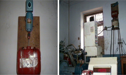
Renewable ethanol is derived from agricultural feedstocks through already improved and demonstrated technologies. The properties of Honge oil, methyl esters and natural gas fuels are presented in Tables and . Biodiesel is blended with ethanol to obtain different fuel blends. A stirrer is mounted inside a fuel tank in order to prevent phase separation. Figure shows a mechanical stirrer used to mix the biodiesel–ethanol blend.
Table 2 Properties of diesel, Honge oil and their respective esters and biodiesel–ethanol blends.
Table 3 Properties of natural gas.
Experimental set-up
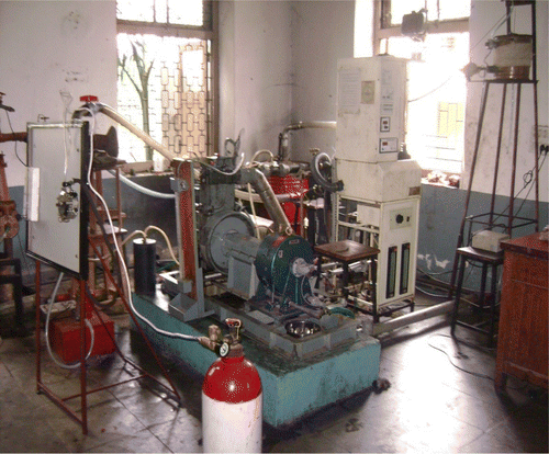
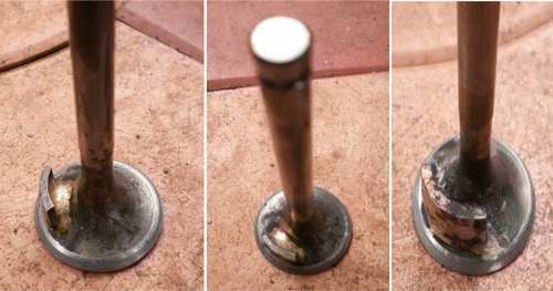
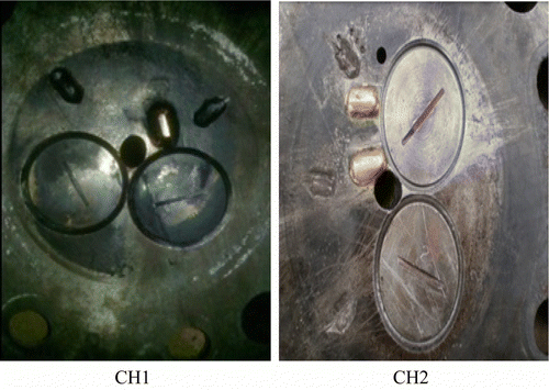
The experiments were carried out on a single-cylinder four-stroke CI engine test rig to operate in a dual-fuel mode. Figure shows the overall view of the test rig that was modified to operate in a dual-fuel mode. The specifications of the engine are given in Table . The engine was always operated at a rated speed of 1500 rpm. A piezoelectric pressure transducer was mounted within the surface of the cylinder head to measure cylinder pressure for the combustion study. The engine tests were conducted with a dual fuel using the CNG and HOME–ethanol blends at both 80% and 100% load conditions. The engine supplier has prescribed an IOP of 200–225 bar for diesel engine operation. However, the IOP of HOME being more viscous than that of diesel (nearly twice) was varied from 200 to 240 bar. The IOP was varied directly in the injector by changing the spring stiffness. This was then checked with a standard calibrated nozzle tester. An optimum injection pressure of 230 bar resulted in overall better performance. The injection timing was kept fixed at 27° Before Top Dead Centre (BTDC) and the compression ratio was varied from 15 to 17.5. Masking was provided on the inlet valve with the angle of mask varying from 50°, 70° and 90°, respectively, as shown in Figure . In addition to the inlet valve masking, the cylinder heads were also suitably provided with different grooves and bridges to study the effect of swirl augmentation on dual-fuel engine performance (Hountalas, Mavropoulos, and Binder 2008). In cylinder head 1 (CH1), one bridge and two grooves were provided while in differently configured cylinder head 2 (CH2), two bridges and three grooves were provided, as shown in Figure . Figure clearly shows the number of bridges and grooves used in both cylinder heads. In order to intensify the air swirl, the number of elliptical grooves was made on the cylinder heads with additional bridges being provided to compensate for the change in compression ratio. Hence the compression ratio of 17.5 was maintained during all the engine-operating conditions in order to study the effect of swirl on the performance of the dual-fuel engine.
Table 4 Specifications of the CI engine.
Tables and , respectively, present the specifications of the exhaust gas analyser and the smoke meter used for the emission measurements with measurement accuracies and uncertainties. The emissions of HC and NOx were measured in ppm, while those of CO and CO2 were measured in percentage (volume based). Smoke was measured in Hartridge smoke units (HSU). In order to reduce the error in the measurement of emissions, five readings were recorded and only their averages are presented in the graphs. The uncertainty of the measured parameters can be estimated with confidence limits of ± 2σ (95.45% of the measured data lie within the limits of ± 2σ around the mean). The percentage uncertainty of the measured parameters can be estimated using the following relation:
Table 5 Specifications of the exhaust gas analyser.
Table 6 Specifications of the smoke meter.
Results and discussion
The engine tests were conducted with a dual fuel using the CNG+HOME and CNG+HOME+ethanol blends at both 80% and 100% load conditions.
Dual-fuel mode of operation on the HOME+CNG blend with a variable compression ratio
Effect of the compression ratio
The experiments conducted enabled to analyse the effect of the compression ratio on the performance of the CNG+HOME dual-fuel engine. The engine was operated at a constant injection timing of 27° BTDC with a CNG flow rate of 0.5 kg/h. The nozzle opening pressure of the injector was maintained at 230 bar for the injected liquid fuel blends.
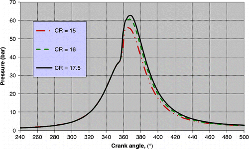
Figure shows the cylinder gas pressure plotted for three compression ratios of 15, 16 and 17.5. The cylinder pressure showed a slight decrease in the peak pressure value with the reduction in compression ratio. This low cylinder pressure was due to the low compression ratio. The effect of the compression ratio on the rate of heat release was much mild. The engine operation at a higher compression ratio beyond 17.5 resulted in an unstable engine operation.
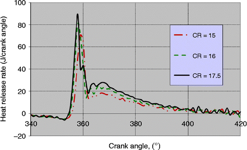
Figure shows the rate of heat release with different compression ratios. Similar to the behaviour of cylinder pressure versus compression ratio, the rate of heat release decreased as the compression ratio decreased.
Effect of the compression ratio on brake thermal efficiency (BTE)
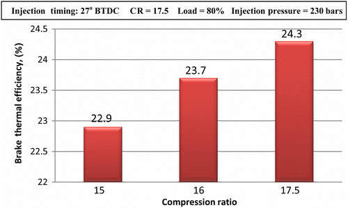
Figure shows variation in BTE versus variation in compression ratio for the HOME+CNG fuel combinations, respectively. As the compression ratio increased, the BTE also increased. This is due to the increased pressure and temperature within the combustion chamber and facilitated complete combustion.
Effect of swirl augmentation techniques
The effect of swirl augmentation techniques in the cylinder CH1 on the performance of the CNG+HOME dual-fuel engine is examined in this section. The engine was operated at a constant injection timing of 27° BTDC with a CNG flow rate of 0.5 kg/h. The nozzle opening pressure of the injector was maintained at 230 bar for the injected liquid fuel blends. The angle of mask was varied from 50° to 90° in steps of 20o angle of mask.
Effect of inlet valve masking: results obtained with modified CH1 (one bridge and two grooves)
Brake thermal efficiency
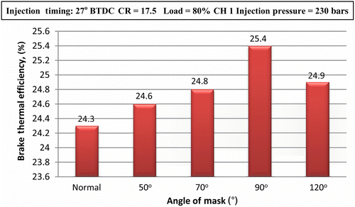
Figure shows variation in BTE versus angle of mask for the HOME+CNG fuel combinations, respectively. As the angle of mask increased, the BTE increased considerably with the dual-fuel combinations until the mask angle of 90°. The reason for this increase in BTE is due to the better mixing of the fuel combinations inside the engine cylinder. However, there was a decrease in BTE at the 120° mask angle due to a drop in volumetric efficiency and incomplete combustion.
NOx emission
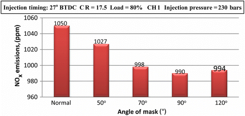
Figure shows variation in NOx emissions versus angle of mask for the HOME+CNG fuel combinations, respectively. As shown in this figure, the angle of mask increased as the NOx emission decreased considerably with the dual-fuel combinations. Increasing the initial swirl reduced the in-cylinder temperature, which in turn reduced thermal NOx emission. However, there was a slight increase in NOx emission being observed at the 120° mask angle due to a drop in volumetric efficiency.
CO emission
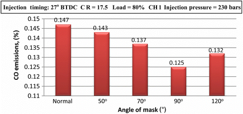
Figure shows variation in CO emissions versus angle of mask for the HOME+CNG fuel combinations, respectively. As the angle of mask increased, the CO emission decreased considerably with the dual-fuel combinations until the 90° mask angle. From this figure, it follows that the reduction in CO emissions is due to the enhanced mixing rate and turbulence in the combustion chamber. However, with 120° angle of masking, there was a slight increase in HC emissions observed and may be due to decreased volumetric efficiency which in turn resulted in incomplete combustion.
Smoke emission
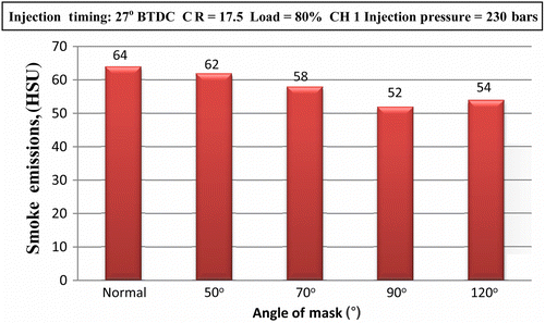
Figure shows variation in smoke emissions versus angle of mask for the HOME+CNG fuel combinations, respectively. As the angle of mask increased, the smoke emission decreased considerably with the dual-fuel combinations until the 90° mask angle. As shown in the figure, swirl improved fuel combustion by reducing the smoke emissions considerably. However, at the 120° mask angle, there was a slight increase in smoke emissions being observed because as the angle of mask increased, the volumetric efficiency decreased, which in turn resulted in incomplete combustion.
HC emission
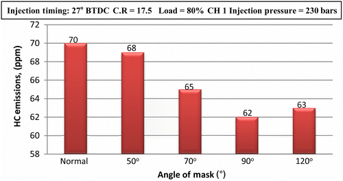
Figure shows variation in HC emissions versus angle of mask for the HOME+CNG fuel combinations, respectively. As the angle of mask increased, the HC emission decreased considerably with the dual-fuel combinations considered. From this figure, it follows that the reduction in smoke opacity with earlier combustion initiation leads to a higher rate of heat release and is affected by swirl augmentation. However, at the 120° mask angle, there was a slight increase in HC emissions being observed because as the angle of mask increased, the volumetric efficiency decreased which in turn resulted in incomplete combustion.
Effect of inlet valve masking: results obtained with modified CH2 (two bridges and three grooves)
Brake thermal efficiency
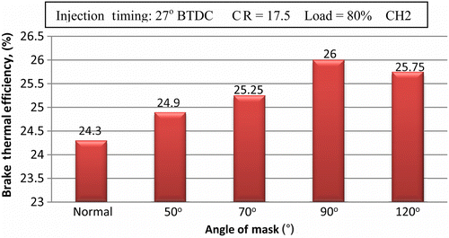
Figure shows variation in BTE versus angle of mask for the HOME+CNG fuel combinations, respectively. As the angle of mask increased, the BTE increased considerably with the dual-fuel combinations. The reason for this increase in BTE is due to the better mixing of the fuel combinations inside the engine cylinder. However, there was a decrease in BTE at the 120° mask angle due to a drop in volumetric efficiency.
Smoke emission
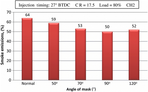
Figure shows variation in smoke emissions versus angle of mask for the HOME+CNG fuel combinations, respectively. As the angle of mask increased, the smoke emissions increased considerably with the dual-fuel combination. As shown in this figure, swirl improved fuel combustion by reducing the smoke emissions considerably. The smoke emission reduced with swirl intensity. However, at the 120° mask angle, there was a slight increase in smoke emissions being observed because as the angle of mask increased, the volumetric efficiency decreased which in turn resulted in incomplete combustion.
CO emission
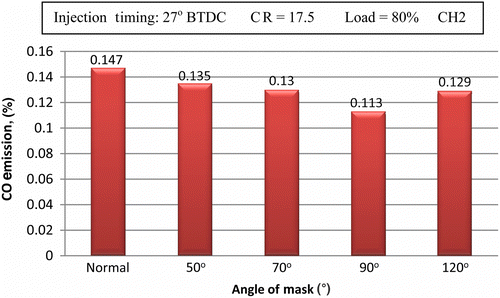
Figure shows variation in CO emissions versus angle of mask for the HOME+CNG fuel combinations, respectively. As the angle of mask increased, the CO emission decreased considerably with the dual-fuel combinations. From this figure, it follows that the reduction in CO emissions is due to the enhanced mixing rate and turbulence in the combustion chamber. However, at the 120° mask angle, there was a slight increase in CO emissions being observed because as the angle of mask increased, the volumetric efficiency decreased which in turn resulted in incomplete combustion.
HC emission
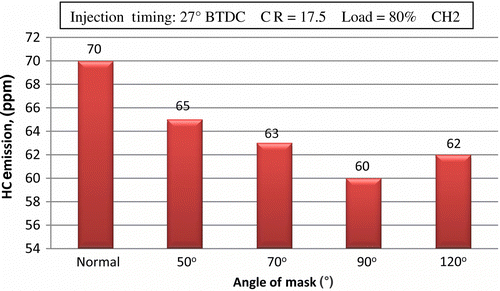
Figure shows variation in HC emissions versus angle of mask for the HOME+CNG fuel combinations, respectively. HC emissions decreased considerably as the angle of mask increased with the dual-fuel combinations. As shown in this figure, the reduction in HC emissions due to earlier combustion initiation that leads to a higher rate of heat release is affected by swirl augmentation. However, at the 120° mask angle, there was a slight increase in smoke emissions being observed because as the angle of mask increased, the volumetric efficiency decreased which in turn resulted in incomplete combustion.
NOx emission
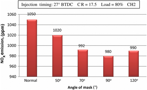
Figure shows variation in NOx emissions versus angle of mask for the HOME+CNG fuel combinations, respectively. NOx emissions decreased as the angle of mask increased considerably with the dual-fuel combinations. Increasing the initial swirl ratio reduces the in-cylinder temperature which in turn reduces thermal NOx emission. However, there was a slight increase in NOx emission being observed at the 120° angle of mask due to a drop in volumetric efficiency.
Comparison made between the modified cylinder head configurations CH1 and CH2
Brake thermal efficiency
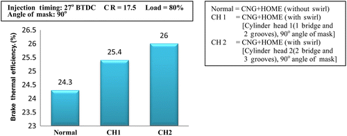
Figure shows variation in BTE versus two modified cylinder heads for the proposed dual-fuel engine operation. As shown in this figure, the increase in the number of bridges and grooves increased the BTE at the 80% load condition. The reason for this increase in BTE is due to the better mixing of the fuel combinations inside the engine cylinder. Moreover, as shown in this figure, BTE was significantly affected by various methods of swirl augmentation. This may also be due to a higher rate of heat release during the early stage of combustion. BTE increased from the CH2 configuration towards the CH1 configuration. This might be due to the enhanced mixing rate in the case of CH2 induced by turbulence in the combustion chamber.
CO emission
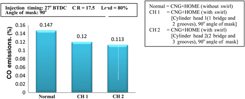
Figure shows variation in CO emission versus two modified cylinder heads for the proposed dual-fuel engine operation. From this figure, it follows that the reduction in CO emissions is due to the enhanced mixing rate and turbulence in the combustion chamber.
NOx emission
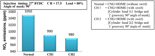
Figure shows variation in NOx emission versus two modified cylinder heads for the proposed dual-fuel engine operation. From this figure, it can be observed that the effect of swirl decreased NOx emission when compared with CH1 with a three-groove 90° mask cylinder head. Generally, increasing the initial swirl ratio reduces the in-cylinder temperature which in turn reduces thermal NOx emission.
HC emission
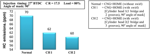
Figure shows variation in HC emission versus two modified cylinder heads for the proposed dual-fuel engine operation. As shown in this figure, swirl improved combustion efficiency by reducing the HC emission considerably. The further decrease in HC emission with the CH2 configuration when compared with the CH1 with earlier combustion initiation leads to a higher rate of heat release and is affected by swirl augmentation.
Smoke opacity
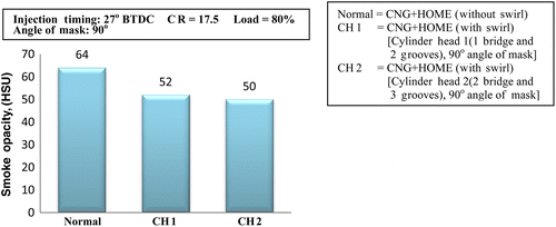
Figure shows variation in smoke opacity versus two modified cylinder heads for the proposed dual-fuel engine operation. As shown in this figure, swirl improved fuel combustion by reducing the smoke emissions considerably. The smoke emission reduced with swirl intensity.
When compared with all the above results obtained, modified CH2 with the 90o angle mask is best suited when compared with modified CH1 and with the other angles of mask (50° and 70°).
Effects of ethanol addition
Brake thermal efficiency
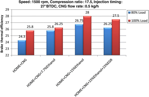
Figure shows the variation in BTE at the 80% and 100% load conditions. The addition of ethanol to HOME improved the efficiency of a dual-fuel engine. This effect arises from the fact that ethanol addition lowers the viscosity of the blend and thus increases the volatility of the mixture. BTE for the CNG+HOME, CNG+HOME+7.7% ethanol and CNG+HOME+15% ethanol blends were found to be 24.3%, 25.8%, 26.75% and 26.25%, respectively, at the 80% load condition and 25.8%, 26.25%, 28% and 27.7%, respectively, at the 100% load condition. However, the addition of ethanol to HOME increased the NOx emission. This negative effect was alleviated by the induction of 10% exhaust gas recirculation (EGR) (Figure ). EGR induction beyond 10% would dilute the charge and hence lower the BTE.
HC emission
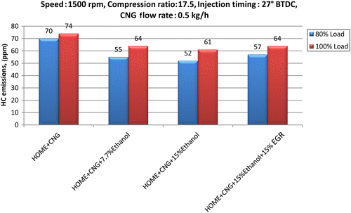
Figure shows the variation in HC during the 80% and 100% load conditions. HC emissions in diesel engines are caused by lean mixture during the delay period and under mixing of the fuel that exits in the fuel injector nozzle at a lower velocity. The addition of ethanol to HOME reduced the HC emission. Also, the addition of ethanol to HOME improved overall combustion characteristics in terms of increased premixed combustion resulting in improved combustion. This is because with CNG being common, the addition of ethanol to HOME lowers the viscosity of the blend as well as increases its volatility. HC emissions for the CNG+HOME, CNG+HOME+7.7% ethanol and CNG+HOME+15% ethanol blends were found to be 74, 55, 52 and 57 ppm, respectively, at the 80% load condition and 106, 64, 61 and 64, respectively, at the 100% load condition.
Smoke opacity
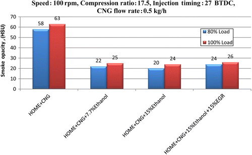
Figure shows the variation in smoke opacity at the 80% and 100% load conditions. The addition of ethanol to HOME reduced the smoke emissions. This is because the presence of the bonded oxygen reduces the probability of the formation of soot nuclei in locally rich zones (Banapurmath and Tewari Citation2010; Lei, Bi, and Shen Citation2011; Xingcai et al. Citation2004). The enrichment of the oxygen content in the fuel due to the addition of oxygenates by both HOME and ethanol resulted in a more complete combustion. The main reason for this reduced smoke emission is due to the improved spray characteristics of the injected liquid fuels. Also, with CNG being common, the addition of ethanol to HOME lowers the viscosity of the blend as well as increases its volatility. Smoke opacity values for the CNG+HOME, CNG+HOME+7.7% ethanol and CNG+HOME+15% ethanol blends were found to be 60, 22, 20 and 24 HSU, respectively, at the 80% load condition and 65, 25, 24 and 26 HSU, respectively, at the 100% load condition.
CO emission
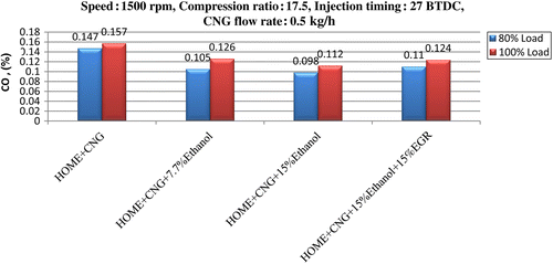
Figure shows the variation in CO at the 80% and 100% load conditions. CO is a toxic by-product and is a clear indication of incomplete combustion of the premixed mixture. CO emission is mainly associated with incomplete combustion prevailing inside the combustion chamber. The addition of ethanol to HOME improved combustion and hence reduced the CO emissions of a dual-fuel engine (Banapurmath and Tewari Citation2010; Lei, Bi, and Shen Citation2011; Xingcai et al. Citation2004). This is because with CNG being common, the addition of ethanol to HOME lowers the viscosity of the blend as well as increases its volatility. CO emissions for the CNG+HOME, CNG+HOME+7.7% ethanol and CNG+HOME+15% ethanol blends were found to be 0.18%, 0.105%, 0.098% and 0.11%, respectively, at the 80% load condition and 0.18%, 0.126%, 0.112% and 0.124%, respectively, at the 100% load condition.
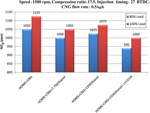
Figure shows the variation in NOx at the 80% and 100% load conditions. The addition of ethanol to HOME reduced NOx emissions of a dual-fuel engine. The NOx emission behaviour for all the fuels was found to be similar at a lower load condition with a slight increase in its magnitude at a higher load condition. This is because at a lower load condition, the adiabatic flame temperature of stoichiometric air/ethanol flame is slightly lower. However, the low cetane number of ethanol led to an increase in the ignition delay and a greater increase in the rates of pressure, resulting in higher peak pressure and combustion temperatures. The exhaust gas temperature increased with an increasing ethanol ratio in the fuel mixture. This high peak temperature increased the NOx emissions. Hence as the ethanol concentration increased, the NOx emission also increased. Also the oxygenates of ethanol–ester fuel combinations resulted in higher NOx emissions due to a more complete combustion than the ester alone (Banapurmath and Tewari Citation2010; Lei, Bi, and Shen Citation2011; Xingcai et al. Citation2004). This is because with CNG being common, the addition of ethanol to HOME lowers the viscosity of the blend as well as increases its volatility. NOx emissions for the CNG+HOME, CNG+HOME+7.7% ethanol and CNG+HOME+15% ethanol blends were found to be 1160, 1000, 1025 and 940 ppm, respectively, at the 80% load condition and 1200, 1050, 1075 and 1000 ppm, respectively, at the 100% load condition. However, the addition of ethanol to HOME unfortunately increased the NOx emission. This negative effect was alleviated by the induction of 10% EGR.
Conclusions
The combustion of HOME+15% ethanol blended with CNG in the dual-fuel engine operated with optimised parameters at an injection timing of 27° BTDC and a compression ratio of 17.5 resulted in reduced pollutant emissions and improved brake thermal efficiency. Based on the experimental findings presented here, the following detailed conclusions were drawn with reference to three parameters investigated in the current study:
Compression ratio. The experimental results showed that with the increasing compression ratio from 15 to 17.5, the BTE increased at both 80% and 100% load conditions. The smoke opacity, HC and CO emissions decreased significantly, while the NOx emissions increased slightly. The optimal compression ratio was found to be 17.5.
Swirl augmentation techniques. The effect of swirl provided with a varied angle of masking showed that the BTE increased by 1% for CH1 and by 2% for CH2. Emissions such as smoke, HC, CO and NOx reduced considerably. The results obtained with an angle of masking beyond 90° are not presented here as the results were not encouraging. It was demonstrated that the BTE increased from the CH1 towards CH2 cylinder head configuration, i.e. with the increased number of grooves and bridges. Emissions such as smoke, HC, CO and NOx reduced considerably. Consequently, swirl augmentation was found to be the main factor that could ensure complete combustion in biofuel-blended dual-fuel engines, including problematic NOx emissions.
Ethanol addition. The experimental findings showed that the addition of ethanol (in HOME–ethanol blends) increased the BTE. However, at more than 15% of ethanol in HOME, NOx emission increased dramatically. To mitigate this NOx increase, the exhaust gas recirculation (10%) was proposed and experimentally proved to be the technique for controlling the NOx level. Furthermore, it was found that for HOME–ethanol blends enriched with ethanol (>15%), it was difficult to achieve a homogeneous mixture and two distinct layers were formed that adversely affected biofuel combustion.
REFERENCES
- Agarwal, A. K.2006. “Biofuels (Alcohols and Biodiesel) Applications as Fuels for Internal Combustion Engines.” Progress in Energy and Combustion Science33: 233–271.
- Ahmadi, P., I.Dincer, and M. A.Rosen. 2011. “Energy, Exergoeconomic and Environmental Analysis and Evolutionary Algorithm Based Multi-objective Optimization of Combined Power Plants with Supplementary Firing.” Energy36 (10): 5886–5898.
- Banapurmath, N. R., K.Marikatti Mahantesh, A. M.Hunashyal, and P. G.Tewari. 2011. “Combustion Characteristics of a Four-Stroke CI Engine Operated on Honge and Jatropha Oil Methyl Ester–Ethanol Blends when Directly Injected and Dual Fuelled with CNG Induction.” International Journal of Sustainable Engineering4 (2): 145–152.
- Banapurmath, N. R., and P. G.Tewari. 2010. “Performance Combustion and Emissions Characteristics of a Single Cylinder Compression Ignition Engine Operated on Ethanol-Biodiesel Blended Fuels.” Proceedings of the Institution of Mechanical Engineers, Part A: Journal of Power and Energy224: 533–543.
- Banapurmath, N. R., P. G.Tewari, and R. S.Hosmath. 2008. “Combustion an Emission Characteristics of a Direct Injection, Compression-Ignition Operated on Hongeoil, HOME and Blends of HOME and Diesel.” International Journal of Sustainable Engineering1 (2): 80–93.
- Banapurmath, N. R., P. G.Tewari, and R. S.Hosmath. 2009. “Effect of Biodiesel Derived from Hongeoil and Its Blends with Diesel when Directly Injected at Different Injection Pressures and Injection Timings in Single-Cylinder Water-Cooled Compression Ignition Engine.” Proceedings of the Institution of Mechanical Engineers, Part A: Journal of Power and Energy223: 31–40.
- Barnwal, B. K., and M. P.Sharma. 2005. “Prospects of Biodiesel Production from Vegetable Oils in India.” Renewable and Sustainable Energy Reviews9: 363–378.
- Benajes, J., S.Molina, J. M.Garcia, and J. M.Riesco. 2004. “The Effect of Swirl on Combustion and Exhaust Emissions in Heavy-Duty Diesel Engines.” Proceedings of the Institution of Mechanical Engineers, Part D: Journal of Automobile Engineering218 (10): 1141–1148.
- Budzianowski, W. M.2010a. “A Comparative Framework for Recirculating Combustion of Gases.” Archivum Combustionis30 (1–2): 25–36.
- Budzianowski, W. M.2010b. “Thermal Integration of Combustion-based Energy Generators by Heat Recirculation.” Rynek Energii91 (6): 108–115.
- Budzianowski, W. M.2011a. “Low-Carbon Power Generation Cycles: The Feasibility of CO2 Capture and Opportunities for Integration.” Journal of Power Technologies91 (1): 6–13.
- Budzianowski, W. M.2011b. “Opportunities for Bioenergy in Poland: Biogas and Solid Biomass Fuelled Power Plants.” Rynek Energii94 (3): 138–146.
- Budzianowski, W. M.2011c. “Sustainable Biogas Energy in Poland: Prospects and Challenges.” Renewable and Sustainable Energy Reviews15. 10.1016/j.rser.2011.07.161.
- Budzianowski, W. M., and R.Miller. 2009a. “Catalytic Converters and Processes in Selected Energy Technologies: I. Gas Turbines and II. Radiant Burners in Drying.” Recent Patents on Chemical Engineering2 (3): 181–206.
- Budzianowski, W. M., and R.Miller. 2009b. “Superadiabatic Lean Catalytic Combustion in a High-Pressure Reactor.” International Journal of Chemical Reactor Engineering7 (1): 1542–6580.
- Budzianowski, W. M., and R.Miller. 2009c. “Towards Improvements in Thermal Efficiency and Reduced Harmful Emissions of Combustion Processes by Using Recirculation of Heat and Mass: A Review.” Recent Patents on Mechanical Engineering2 (3): 228–239.
- Carlucci, A. P., A.de Risi, D.Laforgia, and F.Naccarato. 2008. “Experimental Investigation and Combustion Analysis of a Direct Injection Dual-Fuel Diesel–Natural Gas Engine.” Energy33 (2): 256–263.
- Dincer, I., and M. A.Rosen. 2004. “Exergy as a Driver for Achieving Sustainability.” International Journal of Green Energy1 (1): 1–19.
- Dunbar, W. R., and N.Lior. 1994. “Source of Combustion Irreversibility.” Combustion Science and Technology103 (1): 41–62.
- Heywood, J. B.1988. Internal Combustion Engine Fundamentals. New York: McGraw Hill.
- Hountalas, D. T., G. C.Mavropoulos, and K.B.Binder. 2008. “Effect of Exhaust Gas Recirculation (EGR) Temperature for Various EGR Rates on Heavy Duty DI Diesel Engine Performance and Emissions.” Energy33 (2): 272–283.
- Ishida, M., T.Tagai, and H.Ueki. 2003. “Effect of EGR and Preheating on Natural Gas Combustion Assisted with Gas Oil in a Diesel Engine.” JSME Paper46: 124–129.
- Karim, G. A., and K. S. Burn. 1980. “The Combustion of Gaseous Fuels in a Dual Fuel Engine of the Compression Ignition Type with Particular Reference to Cold Intake Temperature Conditions.” Society of Automotive Engineers, Paper No. 800263, USA.
- Karim, G. A., and N.Amoozegar. 1983. “Determination of the Performance of a Dual Fuel Diesel Engine with Addition of Various Liquid Fuels to the Intake Charge.” Society of Automotive Engineers, Paper No. 830265, USA.
- Karim, G. A.1987. “The Dual Fuel Engine.” In A Chapter in Automotive Engine Alternatives, edited by R. L.Evens. New York, London: Bleham Press.
- Karim, G. A., W.Jones, and R. R.Raine. 1989. “An Examination of the Ignition Delay Period in Dual Fuel Engines.” Society of Automotive Engineers, Paper No. 892140, USA.
- Karim, G. A.1991. “An Examination of Some Measures for Improving the Performance of Gas Fuelled Diesel Engines at Light Load.” Society of Automotive Engineers, Paper No. 912366, USA.
- Lei, J., Y.Bi, and L.Shen. 2011. “Performance and Emission Characteristics of Diesel Engine Fueled with Ethanol-Diesel Blends in Different Altitude Regions.” Journal of Biomedicine and Biotechnology Article ID417421. doi:10.1155/2011/417421.
- Lei, Z., W.Zhang, W.Liu, and Z.Huang. 2010. “Experimental Study on Particulate and NOx Emissions of a Diesel Engine Fueled with Ultra Low Sulfur Diesel, RME-Diesel Blends and PME-Diesel Blends.” Science of the Total Environment408: 1050–1058.
- López, J. M., A.Gomez, F.Aparicio, and F. J.Sanchez. 2009. “Comparison of GHG Emissions from Diesel, Biodiesel and Natural Gas Refuse Trucks of the City of Madrid.” Applied Energy86 (5): 610–615.
- Mahanta, P., S. C.Mishra, and Y. S.Kushwash. 2006. “An Experimental Study of Pongamia pinnata L. Oil as a Diesel Substitute.” Proceedings of the IMechE, Part A: Journal of Power and Energy220: 803–808.
- McTaggart-Cowan, G., W. K.Bushe, P. G.Hill, and S. R.Munshi. 2010. “The Influence of Fuel Composition on a Heavy-duty, Natural-gas Direct-injection Engine.” Fuel89 (3) 752–759.
- Meher, L. C., S. N.Naik, and L. M.Das. 2004. “Methanolysis of Pongmia pinnata (Karanja) Oil for Production of Biodiesel.” Journal of Scientific and Industrial Research63: 913–918.
- Mohamed Selim, Y. E.2005. “Effect of Engine Parameters and Gaseous Fuel Type on the Cyclic Variability of Dual Fuel Engines.” Fuel84: 961–971.
- Murugesan, A., C.Umarani, R.Subramanian, and N.Nedunchezhian. 2009. “Bio-diesel as an Alternative Fuel for Diesel Engines – A Review.” Renewable and Sustainable Energy Reviews13 (3): 653–662.
- Nwafor, O. M. I.2007. “Effect of Advanced Injection Timing on Emission Characteristics of Diesel Engine Running on Natural Gas.” Renewable Energy32: 2361–2368.
- Papagiannakis, R. G., and D. T.Hountalas. 2003. “Experimental Investigation Concerning the Effect of Natural Gas Percentage on Performance and Emissions of a DI Dual Fuel Engine.” Journal of Applied Thermal Engineering23: 353–356.
- Papagiannakis, R. G., D. T.Hountalas, and C. D.Rigopoulos. 2007. “Theoretical Study of the Effects of Pilot Fuel Quantity and Its Injection Timing on the Performance and Emissions of a Dual Fuel Diesel Engine.” Energy Conversion and Management48: 2951–2961.
- Papagiannakis, R. G., C. D.Rakopoulos, D. T.Hountalas, and D. C.Rakopoulos. 2010. “Emission Characteristics of High Speed, Dual Fuel, Compression Ignition Engine Operating in a Wide Range of Natural Gas/Diesel Fuel Proportions.” Fuel89: 1397–1406.
- Pierpont, D. A., D. T. Montogomery, and R. D. Reitz. 1995. “Reducing Particulate and NOx using Multiple Injections and EGR in DI Diesel Engine.” SAE Paper No. 950217.
- Prasad, S. L. V., V.Pandurangadu, G.Prashanthi, V. V.Prathibha Bharathi, and V. V.Naga Deepthi. 2011. “The Effect of Air Swirl in a Diesel Engine.” African Journal of Scientific Research3 (1): 1–212, ISSN 2220-9433204.
- Raheman, H., and A. G.Phadatare. 2004. “Diesel Engine Emissions and Performance from Blends of Karanja Methyl Ester and Diesel.” Biomass and Bioenergy27: 393–397.
- Rao, K. K., D. E. Winterbone, and E. Clough. 1993. “Influence of Swirl on High Pressure Injection in Hydra DI Diesel Engine.” SAE Paper No. 930978.
- Sahoo, B. B., N.Sahoo, and U. K.Saha. 2009. “Effect of Engine Parameters and Type of Gaseous Fuel on the Performance of Dual-Fuel Gas Diesel Engines – A Critical Review.” Renewable and Sustainable Energy Reviews13: 1151–1184.
- Sayin, C., K.Uslu, and M.Canakci. 2008. “Influence of Injection Timing on the Exhaust Emissions of a Dual-Fuel CI Engine.” Renewable Energy33: 1314–1323.
- Selim, M. Y. E.2005. “Effect of Engine Parameters and Gaseous Fuel Type on the Cyclic Variability of Dual Fuel Engines.” Fuel84: 961–971.
- Selim, M. Y. E., M. S.Radwan, and H. E.Saleh. 2008. “Improving the Performance of Dual Fuel Engines Running on Natural Gas/LPG by using Pilot Fuel Derived from Jojoba Seeds.” Renewable Energy33 (6): 1173–1185.
- Szargut, J.2010. “Energy or Exergy.” Rynek Energii90 (5): 3–5.
- Timotey, D. J.1985. “A Simple Technique for Predicting Optimum Fuel Air Mixing Conditions in a Direct Injection Diesel Engine with Swirl.” SAE Paper No. 851543.
- Van Gerpen, J. H., C. W. Huang, and G. L. Borman. 1985. “The Effects of Swirl and Injection Parameters on Diesel Combustion and Heat Transfer.” SAE Paper No. 850265.
- Xingcai, L., Y.Jianguang, Z.Wugao, and H.Zhen. 2004. “Effect of Cetane Number Improver on Heat Release Rate and Emissions of High Speed Diesel Engine Fuelled with Ethanol Diesel Blend Fuel.” Fuel83: 2013–2020.
- Yaliwal, V. S., S. R.Daboji, N. R.Banapurmath, and P. G.Tewari. 2010. “Production and Utilization of Renewable Liquid Fuel in a Single Cylinder Four Stroke Direct Injection Compression Ignition Engine.” International Journal of Engineering Science and Technology2 (10): 5938–5948.

