 ?Mathematical formulae have been encoded as MathML and are displayed in this HTML version using MathJax in order to improve their display. Uncheck the box to turn MathJax off. This feature requires Javascript. Click on a formula to zoom.
Abstract
Cement manufacturing consumes two main types of energy: fuel and electricity. On average, energy costs represent 40% of the total production costs per ton of cement. The challenge is to reduce the consumption of energy to about 3000 MJ/ton clinker without the consumption of massive additional amounts of electricity, which is normally associated with additional fuel-saving measures. This can only be achieved by implementing sound thermal energy optimization measures. Energy-efficient suspension cement kilns are now widely applied and use a cascade of cyclonic pre-heaters of moist particulate feedstock, with heat transfer from hot kiln exhaust gas to particles being a function of heat transfer coefficient, temperature difference and gas–solid contact mode and time. The gas–solid contact mode and time depend on particle movement in cyclones, which has previously been studied by positron emission particle tracking. Heat transfer is governed by Nusselt–Reynolds equations, with gas velocity and properties being a function of the temperature profile along the cascade of cyclones. A stepwise approach of the design thus combines changing hydrodynamics and heat transfer along the successive cyclones, with the overall thermal balance of the cascade as control. This approach leads to major design recommendations, as developed in the present paper.
1. Nomenclature
| a | = | exposed particle surface area (per unit volume of flow gas, m2/m3) |
| C pG | = | specific heat capacity of gas (J/m3 K) |
| C s | = | clinker-to-gas ratio (kg/kg) |
| d 50 | = | cut size of the cyclone (m) |
| D c | = | diameter of the cyclone (m) |
| d p | = | particle size (m) |
| g | = | gravitational constant (m/s) |
| h | = | gas-to-particle heat transfer coefficient (W/m2 K) |
| L | = | length of the turbulent gas–particle contact (m) |
| T G | = | temperature of gas (K) |
| T s | = | temperature of solids (K) |
| U G | = | superficial gas velocity (m/s) |
| v c | = | superficial velocity in the cyclone cross-sectional area (m/s) |
| v i | = | inlet velocity of the cyclone (m/s) |
| t f | = | thickness of the wall layer of the cyclone (m) |
| ΔP | = | pressure drop (Pa) |
| ρG | = | density of gas (kg/m3) |
| ρS | = | density of clinker particles (kg/m3) |
| μG | = | gas viscosity (kg/m s) |
| v yp | = | particle axial velocity (m/s) |
2. General context of the research
Cement manufacturing consumes two main types of energy: fuel and electricity. On average, energy costs represent 40% of the total production costs per ton of cement, up to 60% in the case of lime kilns. Over the past years, fuel economy – achieved by better heat recovery – has been counteracted by rising electricity and fuel costs. Electricity input increased from 14 to 25% of the total cement production costs, with milling and exhaust fans representing 80% of these electricity costs. Both fuel economy and electricity consumption are linked as additional heat recovery stages will induce additional pressure drops in the system, thus increasing the required exhaust power. Theoretical fuel demand for producing cement clinker is determined by mineralogical reactions (∼1800 kJ/kg clinker) and by the heat needed for drying and pre-heating of raw materials. The total fuel consumption in modern kiln systems varies from 3000–3600 kJ/kg (dry process with multi-stage cyclonic pre-heaters and pre-calciners) to 3100–4200 kJ/kg (dry rotary kilns with cyclonic pre-heaters) and 3300–4500 kJ/kg (semi-dry/semi-wet processes). Long rotary kilns and shaft kilns (>5000 kJ/kg) now represent less than 1% of the total production capacity. For other cement kilns, mostly of suspension type, additional measures have to be taken since the 2001 BREF states: ‘For new plants and major upgrades, the best available technique for the production of cement clinker is considered to be a dry process kiln with multi-stage pre-heating and pre-calcination. The associated BAT heat balance value is 3000 MJ/ton clinker.’ From a study published by Berkeley National Laboratory (Worrell, Galitsky, and Price Citation2008), it appears that even modern cement kilns can improve their fuel consumption by 100–200 kJ/kg, with electric savings between 1.5 and 3.2 kW h/ton, leading to CO2 savings of 2.9–5.9 kg C/ton, thus highlighting that energy savings are possible and, indeed, needed.
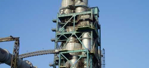
Kiln systems with multi-stage (three- to six-stage) cyclonic pre-heaters are shown in Figure (PSP Engineering a.s. Citation2012). An integrated pre-calciner and tertiary air duct are standard technology for new plants. Under optimized circumstances, such as during performance tests, such a configuration will use 2900–3300 MJ/ton clinker. In practice, the energy consumption of even these plants will rise to 3000–3600 MJ/ton clinker as an annual average because of suboptimal plant utilization and unscheduled shutdowns and startups. The BREF-imposed energy consumption of 3000 MJ/ton clinker can only be achieved by implementing additional thermal energy-saving measures, preferably without the consumption of considerable additional amounts of electricity.
Common measures to partly meet these targets include the improvement of grate coolers to obtain a more uniform distribution of cooling air, a near-stoichiometric yet partly oxidizing kiln condition, a reduction of air leakage, the pre-homogenization of kiln feedstock and the improvement of the even feeding of the kiln. Further issues of concern are the required pre-calcination of the raw meal, and the necessary and potentially feasible improvement of pre-heaters, which are of paramount importance to achieve a high degree of heat recovery, a low pressure drop, a uniform distribution of solids and gas streams and a long gas–solid contact time in a turbulent flow mode to achieve a high rate of heat transfer.
The present paper discusses the hydrodynamic and thermal design of the cyclonic dryer and pre-heater, built as a cascade of five to six cyclone stages (the top stages being commonly in parallel operation to improve de-dusting efficiency). Only a stepwise heat transfer calculation, coupled with gas–solid flow considerations, provides an accurate design. This paper provides a summary of fundamental insights into the gas–solid movement in cyclones, presents an equation to calculate heat transfer coefficient between gas and particles, summarizes the design method and illustrates design results. Particle movement and residence time in a cyclone were extensively studied by the positron emission particle tracking (PEPT) of a radioactively labelled tracer. Since gas velocity itself is a function of the achieved heat recovery and temperature profile along the cascade of cyclones, a stepwise approach of cyclone sizing and thermal design is required, whereby hydrodynamic and heat transfer characteristics are determined in each step, summed up and compared with the overall pre-set or expected thermal balance of the complete cascade of cyclones.
Heat transfer coefficients are defined from appropriate Nusselt–Reynolds equations.
Prior to describing the relevant experimental findings from the literature, it is important to illustrate the flow rates and solid/gas ratios encountered in the specific application for the production of 2000 ton/day clinker, with flue gases leaving the pre-calcination stage at 800–850°C. Due to the decreasing gas temperature along the cyclone cascade and associated increasing gas density, the solid/gas ratio, C s, expressed as kg solids/kg gas, will decrease from about 5 kg/kg at the lower cyclone, to about 1.9 kg/kg at the top cyclones. Flue gas viscosity and conductivity will moreover decrease by a factor of ∼2 from the bottom to the top cyclones. Both factors influence the cyclonic operation and the values of dimensionless numbers such as Reynolds (Re), Nusselt (Nu) and Fedorov (Fe) and the density ratio ρS/ρG.
3. Cyclone pressure drop and particle movement
The applied solid-to-gas ratio C s between 1.9 and 5 kg solids/kg gas is an important factor to be considered in the cyclone operation. The cyclones operating at high temperatures has been reviewed by Dewil, Baeyens, and Caerts (Citation2008), who developed a design approach based on the Euler number (Eu) and the value of the Stokes number at particle cut size (Stk50) and provided a fair prediction at very low solid/gas ratios for cyclone pressure drop and cut size:
Stk50 is related to Eu and includes the cut size of the cyclone (d 50) and the cyclone diameter (D c), as given in Equation (2), presented by Svarovsky (Citation1986). With an increasing temperature, d 50 will increase due to the gas viscosity μG as follows:
Eu and Stk50 are the characteristics of a given cyclone type and related to the geometric cyclone dimensions. The data given in the literature or predicted by Dewil, Baeyens, and Caerts (Citation2008) relate to the conditions of the low values of C s.
Additional research by Dewil, Baeyens, and Caerts (Citation2008), Svarovsky (Citation1986) and Chan et al. (Citation2009) has demonstrated that both cyclone pressure drop and particle movement are interdependent and important factors in cyclone operation and cyclonic heat transfer because the nature of the gas–solid suspension flow mode affects the heat transfer coefficient (Everaert, Baeyens, and Smolders Citation2006).
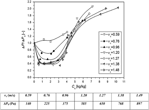
The study of the pressure drop ΔP used two cyclones, both of Stairmand design, with diameters of 95 and 200 mm, and integrated in a circulating fluidized bed rig, in which the circulation rates of both operating gas velocity and solids could be varied. The variation of ΔP in the cyclones as a function of v c and C s is shown in Figure , with the virgin pressure drop at C s = 0 being the reference. Initially, an increase in dust loading decreases the pressure drop as the initial amount of dust in the cyclone acts like a coating on the otherwise smooth cyclone wall, thereby increasing the effective wall friction of the cyclone and thus decreasing the swirl velocity in the cyclone and reducing the magnitude of the pressure drop, as demonstrated by Chan et al. (Citation2009). With further increasing C s, the pressure drop increases strongly up to about 8 kg/kg and levels off if the loading increases further.

It is, however, clear from Figure that well-designed cyclonic pre-heaters operate at C s values between ∼2 and ∼5kg/kg, and thus in the region of a reduced pressure drop, a significant advantage towards the power consumption.
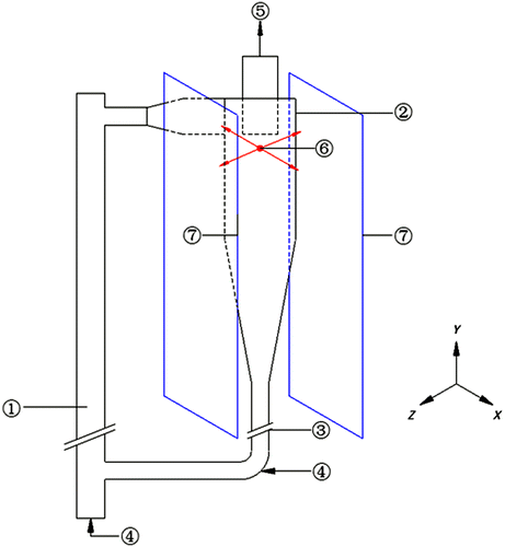
The particle movement was previously examined in detail by PEPT in the experimental set-up of Figure , and has been reported in detail in the paper of Chan et al. (Citation2009).

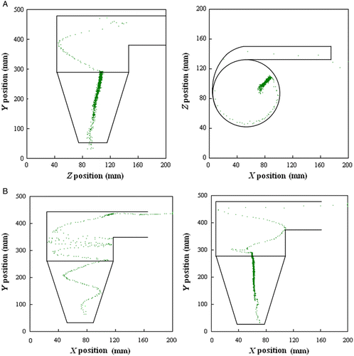
PEPT monitors the movement of a single radioactively labelled particle in real time within the bulk of particles moving, as illustrated in numerous studies (Parker et al. Citation1997; Seville, Ingram, and Parker Citation2005; Fan, Parker, and Smith Citation2006a, Citation2006b). Typical tracer particle tracks are illustrated in Figure (A),(B) for different values of v c and C s. In each case, two orthogonal elevations are shown, X and Y, as recorded by γ-ray cameras located at both sides of the cyclones with each ∼0.5 × 0.6 m2. Air flow rates were selected to operate the cyclone at a velocity (v c) of 0.35–2.7 m/s. C s was varied from 0 to 80 kg/kg. The circulation rate of solids was set by the aeration rate of the L-valve of the circulating fluidized bed (CFB) rig. All air velocities are expressed as a function of the cross-sectional area of the cyclones.

The particles move in a spiral flow pattern in the cylindrical body of the cyclone. This spiral pattern continues in the conical part of the cyclone at low values of C s, but moves in a moving-bed pattern (dense wall layer) at higher C s values. Whereas the residence time of the particles in the spiral flow pattern is very short, it is of the order of 10–20 s in the moving-bed pattern. The residence time τ of particles in the cyclone is obtained experimentally from PEPT trajectories. For C s values approximately above 15 kg/kg, the residence time of solids does slightly decrease as C s values increase. Fitting the initial experimental results of Chan et al. (Citation2009) leads to the following equations to predict the residence time of solids in the cyclone:
The formation of a dense wall layer in the cyclone at moderate to high C s values has two major consequences:
Since ΔP is inversely proportional to the fourth power of the cyclone diameter D c, the existence of a wall layer, of thickness t f, has an influence on the pressure drop, assuming that other factors remain constant. Although the solid layer accumulates mostly in the conical section of the cyclone, it can tentatively be assumed that the effective cyclone diameter is reduced from D c to (D c–2t f): the pressure drop at high solid loading would increase for the 0.2 m ID cyclone, with t f = 0.018 m as [0.2/(0.2–0.035)], i.e. ∼2.2 times the virgin pressure drop. This multiplication factor confirms the findings presented in Figure .
The conical part of the cyclone will not significantly contribute to the heat transfer because the ratio of the tangential particle velocity and the tangential gas velocity is very small (∼0.1), whereas it is 0.5–1 in the cylindrical cyclone body. High solid loadings (C s∼>3kg/kg) should thus be avoided.
The PEPT data can also be used to calculate the tangential and axial velocities of the tracer particle within the cyclone, as reported in Chan et al. (Citation2009). The particles have been observed to have some initial upward velocity (positive v yp), followed by a zone of constant axial acceleration, and ending in a slowly downward-moving dense flow towards the cyclone apex. The initial upward movement occurs over the height of the inlet section. The axial acceleration occurs in the cylindrical body of the cyclone, whereas the dense flow occurs in the conical part of the cyclone. Once entrapped in the dense flow zone, the particle is only subject to small radial movements.
4. Heat transfer in suspensions
Heat transfer characteristics of suspensions have been summarized by different studies to determine the heat transfer coefficient. A study by Everaert, Baeyens, and Smolders (Citation2006) determined the conditions of optimum heat transfer in flowing gas–solid suspensions, recognized to occur at an optimum solid/gas concentration ratio of 3–8 kg solids/kg gas, within the range of applied C s values in the cement cyclonic pre-heaters.
Baeyens, Van Gauwbergen, and Vinckier (Citation1995) derived heat transfer coefficients in large-scale pneumatic dryers, resulting in an empirical equation for the Nusselt number as a power law function of the Reynolds number of the particle, using the particle terminal velocity as the main flow characteristic. This equation does not include C s, since the large-scale plants operated at a fairly constant C s of about 1.5 kg/kg. The application of the equation to cyclone conditions is hence not recommended. A more comprehensive study on cyclone heat exchange has been published by Jain et al. (Citation2006), which results in several important findings:
The optimum heat transfer coefficient (h) from gas to particles is achieved at C s>3–4 kg/kg. Although h increases with v c, the maximum is fairly constant once the optimum C s value has been obtained.
The particle size of the fed powders has a marked influence on h, increasing by about 50% from 163 μm particles to ∼300 μm particles.
Jain et al. (Citation2006) developed a correlation of the heat transfer data as follows (Pr ∼0.68 to 0.69 within the T range under consideration):
(3)
(3)
The Fedorov dimensionless number Fe is not commonly used in powder technology, but is, in fact, an alternative expression of the third root of the Archimedes number, with the difference being the incorporation of (4/3)1/3, itself being ∼1.10 only.
For a staged cyclonic pre-heater, with an average of 100 μm feed size, the heat transfer coefficient remains nearly constant at 40–50 W/m2 K throughout the cyclone cascade, as a result of increasing ρS/ρG, but decreasing Fe and Re. The dominant driving forces in the cyclonic pre-heater thus remain the surface areas exposed by the particles per unit gas volume, and the temperature difference between the flue gas and particles at each stage.
5. Design of the cyclonic pre-heater cascade
From the previous findings, it has been recommended to operate all cyclones at a C s value below 3–4 kg/kg, thus considerably reducing the pressure drop of the cyclone cascade. This implies the use of a lower gas velocity in the bottom cyclones (an increased cyclone diameter). In doing so, the extent of the moving bed in the conical cyclone zone will be limited, thus again improving the turbulent-flow contact time between the gas and particles.
Furthermore, it has been recommended to predict the heat transfer coefficient by Equation (3). When these recommendations have been followed, the heat transfer ratio in each stage can be calculated as follows:
The tangential gas velocity can be predicted by different correlations, which is in fair agreement as demonstrated by Chan et al. (Citation2009). In solving the equation for each stage, the final control is, of course, the overall heat balance of solids and gas, as fixed by the pre-calciner exit temperature (e.g. ∼800°C) and the exhaust gas temperature of the final cyclone stage (100–150°C, as a function of the number of cyclone stages in the system).
The turbulent contact length is defined for each cyclone stage (∼4D c). T G and T S can be proportionally adapted according to the heat balance (4) until the overall heat balance of the cyclonic cascade is closed. In doing so for a five-stage pre-heater, up to 77.8% of the flue gas heat can be recovered. In a six-stage pre-heater, the rate of recovery increases to 82.1%.
Provided C s values of 1–4 kg/kg are considered, the operating pressure drop can also be reduced to 25 or 35% of the virgin pressure drop, as shown in Figure , thus substantially reducing the exhaust fan power consumption. To guarantee a fair de-dusting efficiency of the top stage, this should indeed be executed as two (or three) parallel cyclones, since d 50 is inversely proportional to D c. The local high C s value will moreover contribute to the separation efficiency, well above 99% for an appropriate cyclone design (Dewil, Baeyens, and Caerts Citation2008; Svarovsky Citation1986) and thus with a residual emission prior to final de-dusting between 10 and 12.5 g/N m3.
6. Conclusions
The design of a cascade of cyclonic pre-heaters in suspended cement kilns, and the overall energy economy of the system, can be improved. The factors in the optimum design are (1) the influence of the solid loading on the pressure drop of each cyclone and (2) the ratio of the solid velocity and the tangential air velocity, together with the extent of the turbulent contact zone. Additional design parameters for the cascade of cyclonic pre-heaters include (1) the heat transfer coefficient, again as a function of C s, albeit fairly constant throughout the cyclone cascade, and (2) the exposed surface area of the clinker particles, proportional to C s and to the extent of the turbulent contact zone. Applying the design recommendations of the paper will lead to a heat economy of about 5%, i.e. >150 MJ/ton clinker, without jeopardizing the consumption of electricity, which can even possibly be reduced by operating each cyclone stage within the appropriate C s range.
References
- Baeyens, J. , D. Van Gauwbergen , and I. Vinckier . 1995. “Pneumatic Drying: The Use of Large-Scale Experimental Data in a Design Procedure.” Powder Technology 83: 139–148.
- Chan, C. W. , J. P. K. Seville , X. Fan , and J. Baeyens . 2009. “Particle Motion in CFB Cyclones as Observed by Positron Emission Particle Tracking.” Industrial and Engineering Chemistry Research 48: 253–261.
- Dewil, R. , J. Baeyens , and B. Caerts . 2008. “CFB Cyclones at High Temperature: Operational Results and Designing Assessment.” Particuology 6 (3): 149–156.
- Everaert, K. , J. Baeyens , and K. Smolders . 2006. “Heat Transfer to the Flowing Gas–Solid Dispersion in a CFB-Riser.” Heat Transfer Engineering 26 (7): 1–5.
- Fan, X. , D. J. Parker , and M. D. Smith . 2006a. “Enhancing F-18 Uptake in a Single Particle for Positron Emission Particle Tracking Through Modification of Solid Surface Chemistry.” Nuclear Instrumentation and Methods A 558: 542–546.
- Fan, X. , D. J. Parker , and M. D. Smith . 2006b. “Labelling a Single Particle for Positron Emission Particle Tracking Using Direct Activation and Ion-Exchange Techniques.” Nuclear Instrumentation and Methods A 562: 345–350.
- Jain, A. , B. Mohanly , B. Pitchumani , and K. S. Rajan . 2006. “Studies on Gas–Solid Heat Transfer in Cyclone Heat Exchangers.” Journal of Heat Transfer 128: 761–768.
- Parker, D. J. , D. A. Allen , D. M. Benton , P. Fowles , P. A. McNeil , M. Tan , and T. D. Beynon . 1997. “Developments in Particle Tracking Using the Birmingham Positron Camera.” Nuclear Instrumentation and Methods A 292: 421–426.
- PSP Engineering a.s. 2012. “Kiln Systems, Pre-heaters and Pre-calciners.” Accessed August 2012. www.pspengineering.cz .
- Seville, J. P. K. , A. Ingram , and D. J. Parker . 2005. “Probing Processes Using Positrons.” Transactions of the Institution of Chemical Engineers 83 (A7): 788–793.
- Svarovsky, Ladislav . 1986. “Solid–Gas Separation.” In Gas Fluidization Technology, edited by Derek Geldart , 197–218. New York: John Wiley & Sons.
- Worrell, E., C. Galitsky, and L. Price . 2008. “Energy Efficiency Improvement Opportunities for the Cement Industry.” Berkeley National Laboratory Report, LBNL-72E, January 2008.

