
 ?Mathematical formulae have been encoded as MathML and are displayed in this HTML version using MathJax in order to improve their display. Uncheck the box to turn MathJax off. This feature requires Javascript. Click on a formula to zoom.
Abstract
The aim of this research was to reuse blast furnace slag (BFS) as a mud cake modifier (MCM) to improve the annular isolation quality in oil and gas wells. For the optimum formula of drilling fluid, the effects of MCM on the drilling fluid rheology were investigated. The relationship between the MCM addition and shear strength at cement–formation interface (SSCFI) was evaluated. The experimental results showed that the optimized formula of the drilling fluid has 1.0 wt% MCM and 0.5 wt% XY-27. The simulation results showed that SSCFI increased significantly with the addition of MCM. Based on the mechanism analysis of BFS as an MCM to improve SSCFI, it is found that the transformation of mud cake to agglomerated cake can be the main reason. The application results showed that the success rate of five wells reached 100%, and the rate of quality in cement was 100%. Especially, the average high quality rate of five wells reached 83.7%. Compared with conventional methods, the average high quality rate is increased by 32.6% points. This research provides a new way for sustainable utilization of BFS.
1. Introduction
Blast furnace slag (BFS) is a kind of residue from steel plants. The BFS treatment not only consumes a large amount of manpower, materials and funds, but also occupies plenty of land and causes environmental pollution. So how to take the efficient advantage of BFS is one of the hottest topics in the current research. BFS is a kind of silicate material. The BFS powder obtained by water quenching process has some pozzolanic activity. However, the BFS powder is mainly applied to civil engineering applications at present (Cioffi et al. Citation2001; Chang and Hou Citation2003; Guerrero and Goñi Citation2002; Li and Zhao Citation2003; Mantel Citation1994; Özkana, Yüksel, and Muratoğlub Citation2007; Pal, Mukherjee, and Pathak Citation2003; Smolczyk Citation1978; Windt, Chaurand, and Rose Citation2011; Zhong, Ni, and Li Citation2012). The current price per ton BFS in China is merely from 30 dollars to 40 dollars. It not only has a bad effect on the benefit of BFS reuse, but also seriously restricts further research on BFS reuse. Thus, this research can not only improve the profit of BFS reuse, but also make contribution to the sustainable development of circular economy.
The isolation failure of cement–formation interface is the main problem in well cementing of oil and gas wells (Huang et al. Citation2006; Gu et al. Citation2012), because the mud cake between cement and formation decreases the shear strength at cement–formation interface (SSCFI) (Ladva et al. Citation2005). Based on this, a method of mud to cement (MTC) emerged in the early 1990s (Cowan, Hale, and Nahm Citation1992; Wang, Jiang, and Bu Citation2008). By combining the MTC method and multifunctional drilling fluids, the integrated solidification and cementation of cement–formation interface were achieved, and SSCFI was improved. However, the MTC method had been questioned by many scholars (Benge and Webster Citation1994; Peng et al. Citation2005; Xiao et al. Citation1998). They argued that the MTC solidified body was liable to serious embrittlement. So, the MTC method can only be used in the well cementing of surface casing and intermediate casing, as the MTC solidified body does not have the solidified performance of traditional oil well cement (Xiao et al. Citation1998).
Based on the drilling fluid and cement slurry from Henan oilfield in China, the effects of BFS as a mud cake modifier (MCM) on the drilling fluid rheology were investigated. The relationship of SSCFI with MCM addition and curing time was evaluated. The mechanism of BFS as an MCM to improve SSCFI was analysed. The applications of five wells were also introduced in Henan oilfield in China.
2. Materials
BFS is obtained from Shengda Material Co., Ltd, Wuhan, China. The specific surface area is 0.472 m2/g, the surface average particle size is 4.830 μm, the volume average particle size is 15.997 μm, the forming agent of agglomerated cake and MCM is self-made and the spacer fluid is composed of 85 wt% tap water and 15 wt% forming agent of agglomerated cake. The original drilling fluid and viscosity reducer (XY-27) are from H12-10 well in Henan oilfield. The original drilling fluid is composed of 4.5 wt% bentonite, 0.04 wt% viscosity reducer (FA-367), 0.03 wt% inhibitor (KPAM), 2 wt% filtrate reducer (SMP), 1.5 wt% filtrate reducer (SPNH), 0.08 wt% XY-27 and 3 wt% lost circulation material (DF-NIN-1). The formula of cement slurry is as follows: 100 wt% API Class G oil well cement (Cement Plant of Gezhouba in China), 0.4 wt% dispersant (USZ, from Henan oilfield) and 46 wt% tap water.
3. Methods
3.1 Drilling fluid rheology
3.1.1 Experimental condition
The curing time is 0, 2, 4 and 6 days, respectively, the curing temperature is 75°C and the curing pressure is 0.1 MPa. Based on the results of previous research (Gu and Qin Citation2010), the MCM addition is set as 1.0 and 1.5 wt% and the XY-27 addition is set as 0 (e.g. original drilling fluid), 0.3, 0.5 and 0.7 wt%.
3.1.2 Experimental step
The experimental procedure of drilling fluid rheology is given in five steps as follows:
Weigh drilling fluid, MCM and XY-27 with ACS-30 electronic price scale (Huaying Hengqi Co.,Ltd, Yongkang, China) according to the formula.
Pour the drilling fluid into the pulp cup of JB-12K two-axis high-speed agitator (Hisense Optical Communication Co., Ltd, Qingdao, China), and stir it at 3000 rpm. Then add MCM and XY-27 in turn. Stir them for 5 min at 12,000 rpm until MCM and XY-27 are almost dissolved in the drilling fluid. Measure and record readings on the dial disc at 600, 300 and 3 rpm with ZNN-D6 six-speed viscometer (Hisense Optical Communication Co.,Ltd, Qingdao, China).
Stir this drilling fluid for 20 min at 12,000 rpm. Then pour the drilling fluid into high temperature ageing tank, and roll it for 48 h at 75°C in GRL-BX portable roller heating furnace (Hisense Optical Communication Co., Ltd, Qingdao, China).
Pour the drilling fluid from the ageing tank into the pulp cup, stir it for 5 min at 12,000 rpm and measure and record readings on the dial disc at 600, 300 and 3 rpm.
Repeat steps (3) and (4) twice to get the readings of 4 and 6 days.
3.2 SSCFI
3.2.1 Experimental condition
The curing time of experimental samples is 2, 7, 15 and 30 days, the curing temperature is 38°C in water and the curing pressure is 0.1 MPa. The thickness of mud cake in Henan oilfield is mostly from 0.5 to 0.7 mm, while that of high permeability formation could be up to 1.0 mm during the drilling operation. Therefore, the thickness of mud cake is set as 0.5, 0.7 and 1.0 mm, respectively. The MCM addition is 0 (e.g. original drilling fluid), 0.5, 1.0, 1.5, 2.0 and 2.5 wt%, respectively. The permeability and porosity of simulated wellbores (SWB) are 450 × 10− 3 μm2 and 26%, respectively, which simulate the main isolation section in Henan oilfield. The outside diameter and inside diameter of SWB are 10 and 3.3 cm, respectively. The height of SWB is set to be 5.5 cm in the experiment.
3.2.2 Experimental procedure
A simulated experimental system is built independently. The system includes the preparation of SWB, formation of simulated mud cake, injection of oil well cement slurry, curing of experimental sample and test of shear force at cement–formation interface.
Preparation of SWB. In order to simulate the physical properties and compaction law of interlayer, SWB is prepared as follows:
Determine the proportion of relevant materials and the constant pressure required through a number of simulated experiments.
Screen the yellow sand and normal sand with a certain grain size for SWB.
Weigh materials in accordance with the partitioning determined above, stir uniformly and then get the mixed materials for SWB.
Assemble and locate the polyvinyl chloride (PVC) pipe mould.
Set PVC pipe mould on the frame of the pressure-testing machine, and add the uniformly mixed materials into it.
Press the surface of the mixed materials slowly to a constant pressure with a steely cylindrical indenter, and maintain the pressure for 3–5 min.
Release the pressure, and take out the PVC pipe mould and SWB together.
Leave it aside for 24 h in air, and then put it in the furnace box and heat it. The PVC pipe will swell and peel off from SWB after being heated; thus, an entire SWB is obtained (Figure ).
Figure 1 SWB based on physical properties and compaction law of interlayer. 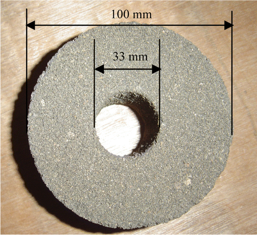
In this experiment, the height of SWB is set to be 5.5 cm, which simulates the thickness of wellbore (h). And the inside diameter of SWB is set to be 3.3 cm, which simulates the borehole size (D).
Formation of simulated mud cake. The formation method of simulated mud cake is prepared as follows:
Put SWB on a glass plate or a smooth board and seal the interface between SWB and the glass plate with temperature butter.
Inject the drilling fluid along the axial direction of SWB uniformly with a large injector until the volume of SWB is filled.
Maintain it in a curing box for 2–12 h under the required temperature, and then a certain thickness of mud cake form. Remove the false and redundant mud cake with glass rods gradually, and then measure the thickness of the mud cake in borehole wall with ruler. Repeat this process until getting the desired thickness of the mud cake (from 0 to 5 mm).
Injection of oil well cement slurry. The cement slurry is prepared and filled into SWB as follows:
Prepare the cement slurry according to API RP 10B. Then inject it into the SWB that is immersed by spacer.
Stir the cement slurry several times with a stirrer bar to ensure that the cement slurry has a good consistency.
Curing of experimental sample. The curing method of experimental sample is as follows:
Use special water proofing methods to process the samples that are injected with the cement slurry.
Put them into a curing box for a certain time. The water temperature can be adjusted so as to simulate the influence of oil and water in the formation on cement–formation interface. Figure shows a curing moulding sample.
Figure 2 Experimental sample of curing moulding. 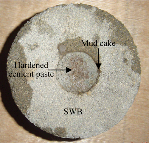
Test of shear force at cement–formation interface. In order to test the shear force at cement–formation interface (F s), the modification of compression tester was carried out (Figure (a)). The test method of F s is as follows:
Take out the experimental sample of curing moulding and wait until they cool to the room temperature naturally.
Figure 3 Test of shear force at cement–formation interface. (a) Modified compression tester and (b) schematic diagram of test. 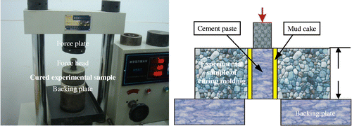
Clear the readings on the table of compression tester, and adjust the force and decline speed of force plate to appropriate ranges.
Place a backing plate on the centre of base, and put the experimental sample of cured moulding and force head on the backing plate (Figure (b)).
When the force on cement paste reaches a certain value, the cement–formation interface will be destroyed. At this moment, the force value showed on the table of compression tester can be used to characterize the maximum value of F s.
Calculation of SSCFI. Based on the shear force (F s) measured above, interlayer thickness (h) and borehole size (D), the SSCFI (p) can be calculated by Equation (1).
where p is SSCFI (MPa), F is the force (kN), S c is the area of cylindrical surface (cm2), F s is the shear force at the cement–formation interface (kN), which mainly depends on the friction force of the mud cake at the cement–formation interface and can be measured in laboratory, h is the interlayer thickness (cm) and D is the borehole diameter (cm). The ‘10’ in Equation (1) is a result of unit conversion.
4. Results and discussion
4.1 Effects of BFS as MCM on drilling fluid rheology
The experimental results of initial gel strength, final gel strength, apparent viscosity, plastic viscosity and yield point of original drilling fluid with MCM and XY-27 are shown in Figure .
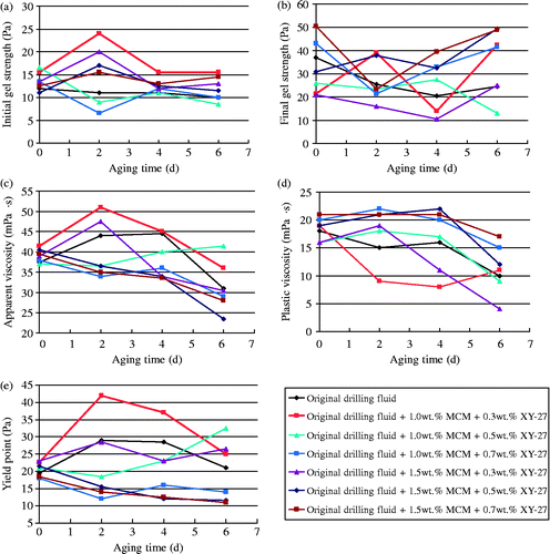
Figure (a) shows the relation between initial gel strength and ageing time. It can be seen that the initial gel strength of original drilling fluid keeps basically constant with ageing time. Comparatively speaking, the initial gel strength of original drilling fluid with 1.0 wt% MCM and 0.5 wt% XY-27 is close to that of original drilling fluid.
Figure (b) shows the relation between final gel strength and ageing time. It can be seen that the final gel strength of original drilling fluid decreases at first, and then increases with ageing time. Comparatively speaking, the final gel strength of original drilling fluid with 1.0 wt% MCM and 0.5 wt% XY-27 is close to that of original drilling fluid.
Figure (c) shows the relation between apparent viscosity and ageing time. It can be seen that the apparent viscosity of original drilling fluid increases at first, and then decreases with ageing time. Comparatively speaking, the apparent viscosity of original drilling fluid with 1.0 wt% MCM and 0.5 wt% XY-27 is close to that of original drilling fluid.
Figure (d) shows the relation between plastic viscosity and ageing time. It can be seen that the plastic viscosity of original drilling fluid decreases with ageing time. Comparatively speaking, the plastic viscosity of original drilling fluid with 1.0 wt% MCM and 0.5 wt% XY-27 is close to that of original drilling fluid.
Figure (e) shows the relation between yield point and ageing time. It can be seen that the yield point of original drilling fluid increases at first, and then decreases with ageing time. Comparatively speaking, the yield point of original drilling fluid with 1.0 wt% MCM and 0.5 wt% XY-27 is close to that of original drilling fluid.
Under comprehensive consideration, the original drilling fluid with 1.0 wt% MCM and 0.3 wt% XY-27 cannot meet the requirement of drilling operation because its initial gel strength, apparent viscosity and yield point might be too big. The original drilling fluid with 1.0 wt% MCM and 0.7 wt% XY-27 also cannot meet the requirement of drilling operation because its final gel strength and yield point might be too low. The rheology of drilling fluid with 1.5 wt% MCM is unstable. Thus, the optimized formula is the original drilling fluid with 1.0 wt% MCM and 0.5 wt% XY-27.
4.2 Relationships of SSCFI with MCM addition and curing time
The experimental results of relationships of SSCFI with MCM addition and curing time are shown in Figure . Compared with conventional methods, the increasing rate of SSCFI with MCM is listed in Table .
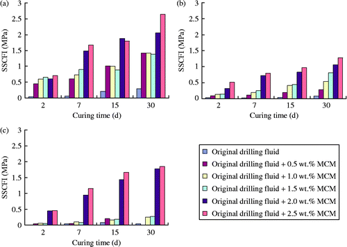
Table 1 Increasing rate of SSCFI based on Figure .
From Figure and Table , the following conclusions can be drawn.
When the curing time and the thickness of the mud cake are constant, SSCFI increases significantly with the MCM addition.
When the MCM addition and the thickness of the mud cake are constant, SSCFI increases gradually with the curing time.
When the MCM addition and curing time, are constant SSCFI decreases significantly as the thickness of the mud cake increases. When the thickness of the mud cake is over 0.7 mm, the MCM addition should be added to 2.0 wt% to get a good effect.
4.3 Mechanism analysis of BFS as an MCM to improve SSCFI
Two premises of integrated solidification and cementation of cement–formation interface are clear. Firstly, there should be enough polar molecules and ions in the solution, which can infiltrate into the mud cake and react with modified mineral, leading to corrosion and disintegration of mineral. Secondly, the supersaturated solution should be stable for enough time so that hydration products can nucleate, grow, cross-connect smoothly and form continuous network to solidify the mud cake. Therefore, available ions from forming agent of agglomerated cake and hydration products of cement are necessary. Diagenesis reaction occurs when these ions (like OH− , ,
, etc.) react with MCM, leading to integrated solidification and cementation of cement–formation interface. The mechanism can be explained in detail as follows.
The alkaline metasomatism reaction (chemical constituents and mineral composition are changed by exchanging matter with intrusion in the agglomerated process) of MCM in the mud cake can lead to dissolution of silicon, replacement of aluminium, exchange of interlayer cation and so on. This will consequently modify the interface. The structure bond in the continuous phase of diagenesis components in the mud cake is destroyed by the hydrated ions from oil well cement slurry, and then the active silicon and aluminium are released.
Accumulation of active silicon and aluminium in the cement slurry filtrate induces diagenesis reaction. Figure shows that the calcium silicate hydrate (CSH) gel (X-ray diffraction intensity is 3096.3, 1670.2 cps) and heulandite gel (X-ray diffraction intensity is 2723.8, 2051.8, 1749.7 cps) are obtained during this process. Figure shows that the thermogravimetry (TG) curves of hardened cement paste and substance between the hardened cement paste and the agglomerated cake are almost coincident, which indicates that the hydration reaction in cement slurry and the curing reaction in the substances are simultaneous. Obviously, the weight loss of TG is about 4.6%, which indicates that a large number of CSH gels and heulandite gels have been formed. Transformation process of the mud cake to the agglomerated cake includes inducing reaction, surface micro-crystallization and interface coupling. Firstly, the energy state of a metastable compound is induced by alkaline ions from oil well cement slurry filtrate, leading to the decrease in reaction barrier. OH− , Ca2+ and
ions play an important part in this reaction. Secondly, the hydration products in gel precipitate more quickly when the metastable compounds exist as micro-crystal nucleus, which accelerates this transformation process. Finally, the mud cake turns into a stable agglomerated cake by inducing reaction, hydration process and hardening process. The microscopic gel structure of the agglomerated cake is closely related to its macroscopic physical properties.
Figure 6 XRD diffraction patterns of agglomerated cake (The data are XRD intensity, cps). 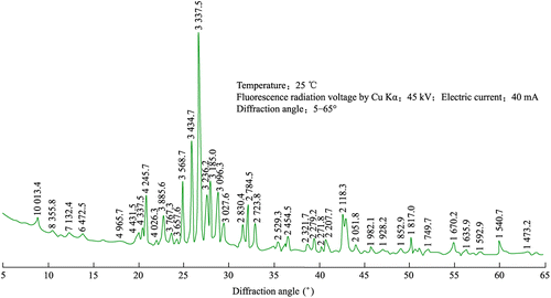
Figure 7 TG curves of hardened cement paste, mud cake, agglomerated cake and substance between the hardened cement paste and the agglomerated cake. 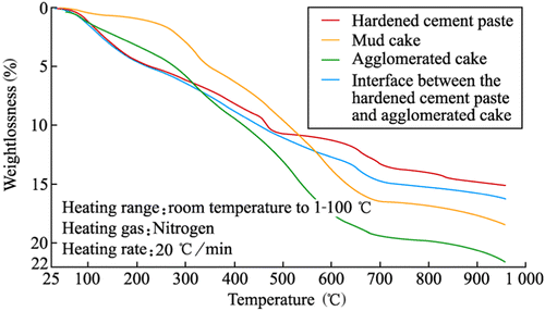
The pore aqueous solution of the structure of agglomerated cake is rich in elements such as S, Mg, Fe, Ca and Si. When these elements accumulate to a certain concentration with the consumption of free water at the later hydration stage of oil well cement, these ions combine and form some new complexes. These complexes are filled into original pore space. Simultaneously, the gels and MCM particles with 10 μm in size that is distributed homogeneously in the agglomerated cake are filled into the capillary pores together, thus improving the pore structure of the agglomerated cake. At the same time, other particles play a framework role in the agglomerated cake, of which the structure is similar to concrete aggregate. It will improve the cementation performance and enhance the microstructure of the agglomerated cake. As a result, the hardened cement paste and the agglomerated cake are cemented together. Thus, SSCFI increases significantly.
5. Application
5.1 Scheme
The well cementing technology, cement slurry system and drilling fluid system should be kept invariable. The process of field experiment can be divided into two steps. Firstly, 1.0 wt% MCM and 0.5 wt% XY-27 are added in the drilling fluid before the reservoir. Secondly, 4 m3 spacer fluid is prepared, which is made up of in-site water and 15.0 wt% forming agent of agglomerated cake.
5.2 Effect
The application effect of five wells in Henan oilfield is given in Tables and . From Table , MCM has a little effect on drilling fluid rheology. So, it can meet the requirement of drilling operation. From Table , the maximum high quality rate is up to 93.79% and the average high quality rate is 83.41% in five wells. The average high quality rate is increased by 32.6% points compared with 50.81% by conventional methods. The application effect of five wells shows that the drilling fluid rheology is good and can meet the requirements of both drilling and cementing operation when the MCM and XY-27 addition are 1.0 and 0.5 wt%, respectively. Meanwhile, the application effect matches the experimental results of the drilling fluid rheology.
Table 2 Application effects of MCM on drilling fluid rheology from five wells.
Table 3 Application effects of five wells.
6. Conclusions
BFS as MCM have some influence on the drilling fluid rheology, but it can meet the requirements of drilling operation when adding 0.5 wt% XY-27 in original drilling fluid. For Henan oilfield in China, the optimum formula of drilling fluid is the original drilling fluid with 1.0 wt% MCM and 0.5 wt% XY-27.
SSCFI increases significantly with the curing time and MCM addition. Under the same condition, SSCFI increases with MCM addition amount. But with the increase in the thickness of the mud cake, SSCFI decreases significantly. When the thickness of the mud cake is over 0.7 mm, the MCM addition should be added to 2.0 wt%.
The mechanism of BFS as an MCM to improve SSCFI is that the forming agent of the agglomerated cake is used to modify and dispose the mud cake interface and make it react with MCM, and finally to form tight agglomerated cake (e.g. MTA). The multicomponent synergism of BFS as MCM could be studied for further research.
The application results of five wells showed that the original drilling fluid with 1.0 wt% MCM and 0.5 wt% XY-27 meets the requirements of drilling operation. The annular isolation quality of BFS as MCM is better than the conventional methods.
The research results of this article not only expand the application range of BFS, but also are beneficial to the high efficient production of oil and gas reservoir.
Additional information
Funding
References
- Benge, O. G. , and W. W. Webster . 1994. “Evaluation of Blast Furnace Slag Slurries for Oilfield Application.” In Proceedings of the Drilling Conference. 15–18 February 1994, Dallas, TX, USA. Richardson, TX: Society of Petroleum Engineers (SPE).
- Cioffi, R. , L. Maffucci , L. Santoro , and F. P. Glasser . 2001. “Stabilization of Chloro-Organics Using Organophilic Bentonite in a Cement-Blast Furnace Slag Matrix.” Waste Management 21: 651–660.
- Chang, P. K. , and W. M. Hou . 2003. “A Study on the Hydration Properties of High Performance Slag Concrete Analyzed by SRA.” Cement and Concrete Research 33: 183–189.
- Cowan, K. M. , A. H. Hale , and J. J. Nahm . 1992. “Conversion of Drilling Fluids to Cements with BLAST Furnace Slag: Performance Properties and Applications for Well Cementing.” In SPE Annual Technical Conference and Exhibition. 4–7 October 1992, Washington, DC, USA. Richardson, TX: Society of Petroleum Engineers of AIME.
- Gu, J. , P. Zhong , C. Shao , S.H. Bai , H. Zhang , and K. Li . 2012. “Effect of Interface Defects on Shear Strength and Fluid Channeling at Cement–Interlayer Interface.” Journal of Petroleum Science and Engineering 100: 117–122.
- Gu, J. , and W. Z. Qin . 2010. “Experiments on Integrated Solidification and Cementation of the Cement–Formation Interface Using the Mud Cake to Agglomerated Cake (MTA) Method.” Petroleum Exploration and Development 37: 226–231.
- Guerrero, A. , and S. Goñi . 2002. “Efficiency of a Blast Furnace Slag Cement for Immobilizing Simulated Borate Radioactive Liquid Waste.” Waste Management 22: 831–836.
- Huang, H. f. , Y.H. Bu , H. Tian , and R.H. Wang , 2006. “Bonding Strength Experiment of Mud to Cement Fluid on the Second Interface.” Journal of China University of Petroleum (Edition of Natural Science) 30: 46–50.
- Ladva, H. K. J. , B. Craster , T. G. J. Jones , G. Goldsmith , and D. Scott . 2005. “The Cement-to-Formation Interface in Zonal Isolation.” Journal of Petroleum Technology 57: 41–44.
- Li, G. Y. , and X. H. Zhao . 2003. “Properties of Concrete Incorporating Fly Ash and Ground Granulated Blast-Furnace Slag.” Cement and Concrete Research 25: 293–299.
- Mantel, D. G. 1994. “Investigation into Hydraulic Activity of Five Granulated Blast Furnace Slags with Eight Different Portland Cements.” ACI Material Journal 91: 471–477.
- Özkana, Ömer , Isa Yüksel , and Özgür Muratoğlub . 2007. “Strength Properties of Concrete Incorporating Coal Bottom Ash and Granulated Blast Furnace Slag.” Waste Management 27: 161–167.
- Pal, S. C. , A. Mukherjee , and S. R. Pathak . 2003. “Investigation of Hydraulic Activity of Ground Granulated Blast Furnace Slag in Concrete.” Cement and Concrete Research 33: 1481–1486.
- Peng, Z. G. , Y. Y. He , C. J. Liu , and Q. Feng . 2005. “Basic Causes Analysis of Cracking of MTC Solidified Body with Cinder.” Natural Gas Industry 25: 72–74.
- Smolczyk, H. G. 1978. “The Effect of Chemistry of Slag on the Strength of Blast Furnace Slags Cements.” Zement–Kalk-Gibs 31: 294–296.
- Wang, R. H. , L. L. Jiang , and Y. H. Bu . 2008. “Experimental Study on Hydration Mechanism of Slag MTC.” Acta Petrolei Sinica 29: 442–446.
- Windt, L. D. , P. Chaurand , and J. Rose . 2011. “Kinetics of Steel Slag Leaching: Batch Tests and Modeling.” Waste Management 31: 225–235.
- Xiao, Z. X. , Q. L. Zhao , X. Chen , and Z. Y. Fan . 1998. “The Induced Mechanism of Crystal During Hydrate of Blast Furnace Slag.” Acta Petrolei Sinica 19: 117–121.
- Zhong, S. Y. , K. Ni , and J. M. Li . 2012. “Properties of Mortars Made by Uncalcined FGD Gypsum-Fly Ash-Ground Granulated Blast Furnace Slag Composite Binder.” Waste Management 32: 1468–1472.