Abstract
This paper deals with simplifying the environmental evaluation of an innovative sub-system related to the future complex system that will include it, by using evolving generic models built on a limited number of characteristics. For a complex system range, the evolving approach of the environmental modelling aims to generate a learning dynamics, to avoid the paralysing complexity induced in design by the valuation of many components according to many impact categories. Applied to the automotive sector, dendrograms are made with results of life cycle assessments (LCA) of 17 vehicles for 4 environmental indicators and on 3 life cycle steps. In an iterative process, a limit condition threshold on the resulting relative errors aims to cluster the vehicles. First, several calculation methods of dendrograms are tested. Second, the influence of the limit condition on the models is observed. Lastly, by simulating the vehicle population increase, the modelling capacity to evolve is tested. Five vehicle characteristics are sufficient to identify a model to be equivalent to the future vehicle. While the number of clusters is increased to simplify their identification with the system characteristics, the relative error variability increases too. The generic models are stable when adding LCA's results.
1. Background
1.1. Environmental evaluation of products
Companies are more and more encouraged by governments, non-governmental organizations and consumers associations, to evaluate and improve the environmental performances of their products with a life cycle and multi-criteria approach. The most widespread methodology for the environmental evaluation is the life cycle assessment (LCA) of products (Finnveden et al. Citation2009; Jacquemin, Pontalier, and Sablayrolles Citation2012). The international standards ISO 14040:2006 and 14044:2006 provide guidelines and a methodology framework of LCA. A lot of data and a very long time are needed to implement a LCA on a complex system; for instance, it may require more than 800 parameters during 3 months to make the LCA of an automobile. Often it is made by a dedicated team at the end of the product design and innovation process (DIP), when the product is entirely designed and manufactured. At this stage, it is too late for engineers to re-design their products. Therefore, in order to design more environmentally friendly products, companies must take into account the dimension ‘Environment’ earlier in the DIP.
The DIP is clearly complex (Tingström and Karlsson Citation2006): it is structured by complex organizations fed by complex information systems. Taking into account those structural and informational specificities is essential to integrate the environmental aspects (Johansson and Magnusson Citation2006; Le Pochat, Bertoluci, and Froelich Citation2007). Using a LCA tool during the DIP is a complicated task from a technical and organizational point of view (Millet et al. Citation2007). Although there is a research field to implement LCA based on the interoperability between design tools that facilitate data exchange (Rio, Reyes, and Roucoules Citation2013), such a strategy needs established environment skills within the company in order to analyse LCA results. Therefore, companies need eco-design tools that are developed to be integrated in the DIP, and to develop environmental skills within the company.
Integrating specific eco-design tools in the DIP of a company has been widely investigated. Companies must take into account simultaneously organizational and technical aspects (Johansson, Greif, and Fleischer Citation2007). Indeed, according to Millet et al. (Citation2004), when a company would like to initiate an eco-design method, it has to deal with a ‘double paralysing complexity: how to introduce the fuzzy environmental dimension in the already hyper constrained universe of the product design process’. This paralysis leads companies to be reluctant to design a more environmentally friendly product. Millet et al. think that tools are the support of an organizational learning revealing new governing values. Many tools have been developed (Baumann, Boons, and Bragd Citation2002; Bovea and Pérez-Belis Citation2012) to help companies to evaluate and improve their products from an environmental point of view. A progressive approach for integrating these tools is required (Jacqueson, Millet, and Aoussat Citation2001): it is essential to gradually expand the Environment dimension from the regulation framework to a sustainable perspective. An eco-design method is generally undertaken in two phases: the diagnostic phase and the improvement phase. This article is focused on the environmental diagnostic phase and does not take into account economic or social concerns of sustainable development.
1.2. Automotive sector specificities
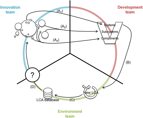
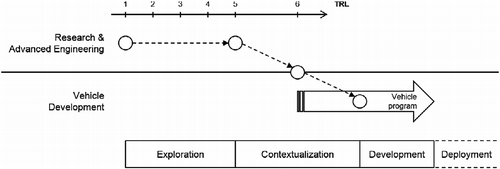
The experimental field in this paper is a car manufacturer whose goal is to initiate an eco-design method during the innovation phase. For a car manufacturer, innovations are most of the time not very intrusive, have an incremental nature and concern sub-systems or components (Oltra and Saint Jean Citation2009). A set of innovations is generally proposed by the innovation team to the routine design of the complex system, which Beaume, Maniak, and Midler (Citation2009) represent as a flow of ‘innovative features’ from the innovation structure to the vehicle programme structure during the ‘contextualization phase’. Figure adapted from Beaume et al. shows that both structures are completely separated. Such a company produces a range of automobiles that are complex products. With regard to the environmental evaluation of complex systems, the aggregation of LCA results of subsystem's components would give the LCA of the subsystem. In the same way the aggregation of LCA results of subsystems would give the LCA of the global product (Graedel et al. Citation2005). Thus, eco-designing a complex system may mainly be achieved at two levels: at the global system level, or at the sub-system or component level. The first case may lead to large scale actions as comparing several different choices of product architecture, or materials; it is nevertheless difficult to conduct this kind of actions because sufficient quantity of data is needed to make the evaluation, and the company strategy is engaged over the long term. On the opposite, the eco-design of a sub-system or a component is easier because a smaller quantity of data is needed; but the impact of the ensuing actions is lower.
In the automotive industry, car manufacturers are making LCA either on the complete vehicle (Finkbeiner and Hoffmann Citation2006; Schweimer and Levin Citation2000) or on subsystems (Keoleian et al. Citation1998; Schmidt and Beyer Citation1999); they are also developing eco-design methods, e.g. Ford's Product Sustainability Index (Schmidt Citation2006), Volvo's Environmental Priority Strategies (Karlsson, Steen, and Wendel Citation1997) and Environmental Effect Analysis (Tingström and Karlsson Citation2006) methods, or Toyota's Eco-Vehicle Assessment System (Nakano and Hirao Citation2011). With the study on the life cycle design of an air intake manifold, Keoleian and Kar (Citation2003) conclude that the evaluation of the integration consequences of the innovative subsystem should be done at the future complex system level, but the environmental profiles of the complex systems are needed. As there are few data available during the innovation phase, the complex systems must be represented by models. Neither the majority of tools developed by car manufacturers, nor the majority of the available tools for eco-designing subsystems in the innovation phase (Bocken et al. Citation2011; Gasafi and Weil Citation2011; Poudelet et al. Citation2012) make it possible to use models for the simplification of innovative subsystems evaluation.
Figure may be a representation of the research question. First, the innovation team (at the top left) makes innovative components (A3), subsystems (A2) or more rarely complete systems (A1). Some innovative features are integrated into an existing system that is taken by the development team of vehicle programme (at the top right). At the end of the DIP, the system is generally evaluated by the environment team (at the bottom) that makes a LCA (B). The results of the LCA are saved in a database (C). The research question is: how to close the DIP cycle in order to evaluate the innovation features during the contextualization phase? The goal in this paper is to develop environmental vehicle models that will be used in a dedicated tool in order to make the contextual evaluation of an incremental innovative subsystem without evaluating the system entirely by developing vehicle models.
2. Issues
The goal of this paper is to present how the complex system that will include the innovation is modelled in a systematic way in order to avoid its complete environmental evaluation. Four key questions are related to this goal. The first one concerns the specificities of car manufacturer's product: they do not produce one kind of vehicles but a complete range. Each vehicle is different in terms of car classification (city, sedans, sports, etc.), motorization performances (diesel, gasoline, hybrid, etc.), bill of materials (BOM), etc. Q1: How to make an environmental modelling in order to represent the car manufacturer's entire range of vehicles?
The second question deals with the DIP cycle: the product design evolves after each design iteration in a continuous improvement system. Every project that begins may use capitalized data and knowledge from previous projects, and every project that ends may feed data knowledge bases. The modelling must take into account this evolution and have therefore the capacity to update. Q2: How to make an environmental modelling in order to support the continuous improvement of vehicles?
Lastly, in order to implement a learning strategy, a loop of organizational learning should be generated, fed by data feedbacks from the series of projects of the company, and oriented by an expansion strategy when taking the dimension ‘Environment’ into account, i.e. from a rough monocriterion eco-design approach to a detailed ‘Design for Environment’ approach. Q3: How to make an environmental modelling in order to generate a loop of learning around the dimension ‘Environment’?
In the environmental modelling literature, research has been focused on two options. The first one consists of building a product parameterized model from relevant physical parameters of the product, e.g. BOM, use consumption, etc. This method was used by Bohm et al. (Citation2010), Ostad-Ahmad-Ghorabi and Collado-Ruiz (Citation2011), Sousa and Wallace (Citation2006), who identified, by using clustering methods, the design parameters that define the product and thus form the inputs of a simplified LCA. Collado-Ruiz and Ostad-Ahmad-Ghorabi (Citation2010) developed a parameterization based on the detailed definition of functional units to categorize different products. Geyer (Citation2008) implemented a parameterized model of LCA to simulate the impact of a material change in the automotive context on the greenhouse gases emissions; it has been implemented in the tool ‘Design Advisor’Footnote1 developed by WorldAutoSteel and dedicated to the automotive sector. The BOM of a vehicle is parameterized in such a way that a vehicle model can be defined with a set of parameters (mass, dimensions, shape, etc.). Then, the user may define old and new modules, and relate the global warming potential (GWP) impacts and the changing cost to the vehicle. The second option consists in building models directly with the environmental impacts resulting from a LCA. Some authors used clustering methods directly on the LCA results and thus defined environmental typologies (Andriankaja, Bertoluci, and Millet Citation2013) or classes (Curzons et al. Citation2007) of products, becoming the reference in a simplified comparative LCA. The models are environmental archetypes of products built on the environmental classes. The first option fits the requirements of the comparisons of several products that have different functionalities in order to categorize them. In the second option, the same functional unit is used in all LCA in order to compare the products. It is therefore adapted to the comparison of several ranges of the same product, e.g. a car or an airplane, and needs to have some LCA of previous products to create clusters.
None of the previous examples take into account both technical (key question Q1) and organizational (key questions Q2 and Q3) aspects at the same time for making a contextual evaluation of innovative subsystems, i.e. for relating the environmental impacts of an innovative feature to the complete system. There is an obvious lack of research in taking into account technical and organizational issues in the environmental modelling, as recommended by Johansson, Greif, and Fleischer (Citation2007).
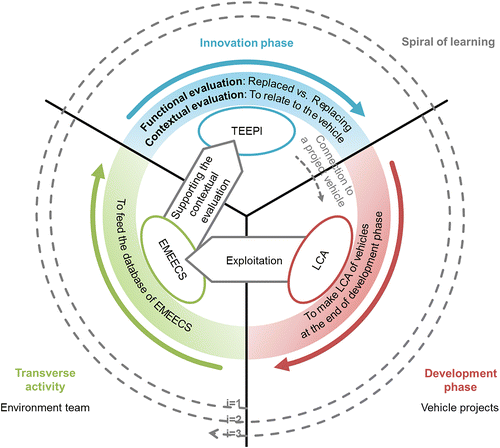
We have developed an approach to build evolving models for the environmental evaluation of complex systems that we named EMEECS. The EMEECS must be built to be used in a dedicated tool for evaluating the environmental impacts of innovative features on the vehicle. This tool is named tool for evaluating the environmental performances of innovations (TEEPI). The user makes the LCA of the initial and innovative features. He/she chooses the right EMEECS for his/her application by selecting the relevant vehicle characteristics that correspond to the vehicle programme into which the innovative solution will be integrated. He chooses the right assembly plant for which an environmental profile is available. Lastly, the initial feature values are subtracted to the EMEECS values, then the assembly plant values and the innovative feature values are added to the EMEECS values. The original EMEECS values and the transformed EMEECS values are compared to highlight the evolution of the environmental profile of the vehicle. EMEECS are tested at a French car manufacturer and they are supposed to satisfy the following (Figure ):
On the technical point, the contextual environmental evaluation of a sub-system, i.e. to relate the environmental impacts of a sub-system to the complex system, in the dedicated tool (named TEEPI in Figure ).
On the organizational learning point, the expansion of taking into account the Environment dimension and the vehicle design evolution, represented by a loop generating building iterations of EMEECS that is defined by a succession of learning phases noted i and shown on Figure by a grey dotted line loop.
3. Research methodology
The EMEECS model takes as its starting point the key idea that there are archetypes of environmental impacts calculated on several life cycle steps of complex system classes, i.e. the user of the proposed method will directly deal with the environmental impacts of the initial and innovative solutions and of the global system. The complex system classes are thus created by applying the hierarchical agglomerative classification (HAC) method (Hastie, Tibshirani, and Friedman Citation2001) on previous LCA's results. The classes from the HAC are therefore the EMEECS: the environmental indicator value of the EMEECS is equal to the average of the class, and the uncertainty of the EMEECS is equal to the standard deviation of the class.
Therefore, the EMEECS should first be identified with a restricted number of vehicles' characteristics; this number would directly be linked with the number of classes: the more the classes, the more the vehicles' characteristics are needed. A moderate level of number of classes created from a starting sample would be equal to at least one half of the number of the sample's individuals. Second, creating vehicle models would generate a modelling error that is intrinsic to the EMEECS. The following can be assumed: the more the classes, the more the errors. A compromise should be found between the number of classes and the errors. As it is acknowledged by Bala et al. (Citation2010), 10% should be considered as a moderate level of discrepancy. Third, the EMEECS should be stable regarding the vehicle design evolution as the learning phases follow one another. Fourth, the EMEECS should be built in order to permit the expansion of the dimension ‘Environment’, i.e. adding life cycle stages and environmental indicators.
3.1. Conventions
In this paper, it is considered that, for the first learning phase i = 1, 17 LCA of cars (Table ) on the full life cycle and for 10 environmental indicators such as global warming, eutrophication, acidification, metal depletion and so on are available. The functional unit that is common for all those LCA is ‘Transporting passengers and goods over 150,000 km during 10 years according to the new European driving cycle NEDC’. This functional unit is defined on an average mileage and a lifetime used by the majority of car manufacturers. Moreover, the emission measurements of pollutants during the use phase are only available on the NEDC, allowing comparing vehicles. Nevertheless, NEDC is not representative of the reality; this study will need to be supplemented by the new driving cycles worldwide harmonized light vehicles test procedures (WLTP) expected in 2014.
Table 1 List of available LCA results of cars.
The production, use and maintenance, and end-of-life are considered. The painting and the assembly done during the production phase are directly related to the assembly plant; they are not considered in this paper because they are taken into account with creating typologies of assembly plants in future work: the environmental typologies of assembly plants would be added to the EMEECS's environmental indicator values.
3.2. Technical issues
By applying a HAC on the collected LCA (see Section 3.2.1), cars are grouped into classes; an iterative process based on a boundary condition (see Section 3.2.2) leads to identify optimal classes.
3.2.1. Hierarchical agglomerative classification
Given a set Vi of vehicles vj with cardinality , a set Xi of environmental indicators xk with cardinality
and a set Yi of life cycle steps yl with cardinality
. The LCA of the vehicle vj gives the value of an environmental indicator xk at a life cycle step yl; this value is noted as wjkl. The averages
(respectively,
) and standard deviations
(respectively,
) are calculated over the set Vi of vehicles vj for the environmental indicator xk and the life cycle step yl (respectively, the full life cycle).
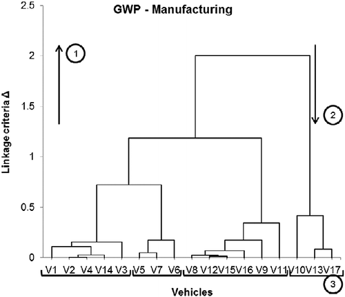
Because of the HAC treatment, vehicles that have similar LCA results are grouped into classes, by making dendrograms (e.g. see Figure for the dendrogram on the manufacturing step and for the GWP). The elements to be classified are vehicles of which the original variables are environmental indicator values per life cycle step and expressed in different units; so, the standard score associated with the original variables is calculated for each life cycle step (Equation (1)) and for the full life cycle (Equation (2)) (see the Appendix Table 1).
The cluster dissimilarity metric δ – or distance between elements – is the Euclidean distance, and the linkage criteria Δ – or distance between classes – is the average linkage clustering. The vehicles or clusters of vehicles that have the minimum linkage criteria (Y-axis on Figure ) are grouped together, and a tree turned upside down named ‘dendrogram’ and noted d is built (up arrow (1) – Figure ): the ‘trunk’ is at the top and the ‘branches’ are at the bottom. Each branch is a cluster of vehicles.
In view of the nature of the original variables, there are four ways to calculate the cluster dissimilarity, and as many groups of dendrograms, with D the set of dendrograms dkl calculated for the environmental indicator xk and the life cycle step yl:
Group (D1): indicator and step accumulations, one dendrogram,
(see the following Equation (3))
(3)
Group (D2): step accumulation and per indicator, N(Xi) dendrograms,
(see the following Equation (4))
(4)
Group (D3): indicator accumulation and per step, N(Yi) dendrograms,
(see the following Equation (5))
(5)
Group (D4): per step and per indicator, N(Xi) * N(Yi) dendrograms,
(see the following Equation (6))
Given cklm the mth class of the dendrogram dkl. The linkage criteria between two classes cklm and that, respectively, hold
and
vehicles, are calculated as follows in Equation (7):
3.2.2. Iterative process to determine optimal classes of cars
Once finalized, the dendrogram is used from top to bottom. Each branch and the trunk itself are groups of vehicles. Let be the set of classes cklm in the dendrogram dkl. For each class cklm of the dendrogram dkl, the average
and the standard deviation
are calculated over the values wjkl of the vehicles included in the class cklm. The average
represents the value of the class and the standard deviation
represents the uncertainty of the class. By using the dendrogram from top to down, the number of classes
evolves from 1 (the trunk) to the number of vehicles in the dendrogram
. Therefore, there is a number of classes
that would be optimum according to the allowed maximum error between the value of the class
and the values wjkl of the vehicles in the class. The relative error ϵjklm between the value of the class
and the values wjkl of the vehicles in the class is calculated (8):
The optimal classes, with which the EMEECS are built, are determined by the following boundary condition (C), and for each dendrogram:
(C) The relative errors committed by the average
of the class cklm related to the values wjkl of the environmental indicators of vehicles vj included in this class must be inferior to a maximum limit ϵmax in terms of absolute value, i.e. (Equation (9)):
The iterative process starts from the trunk, where the vehicles are grouped into one class (N (Ckl) = 1) and go down towards the branches (down arrow (2) – Figure ). If the condition (C) is satisfied on a branch, then the associated class is considered as optimal; else the branch is divided into two sub-branches (N(Ckl) = N(Ckl)+1) and the process is iterated on both sub-branches. Once the iterative process is over, the error relative mean and standard deviation
are calculated on all the dendrograms of the group at which this iterative process is applied.
An extreme case would appear if the environmental profile of vehicles would be very different and the vehicles would not be grouped in classes; in this case, there would be as many classes as vehicles and dendrograms. To measure the reduction potential, the rate of class number reduction τr is defined in the following Equation (10):
We think that there is a compromise between a low level of errors and the high rate of class reduction in order to create classes that are identifiable with few vehicle's characteristics.
3.3. Organizational issues
LCA are made by the Environment team for all the life cycle steps (including upstream and downstream logistics) and with 10 environmental and flow indicators (including abiotic depletion, acidification, eutrophication, global warming and photochemical ozone creation). But, as it is stated in the issue, the integration of a new dimension within the product development and innovation process must be progressive. Integrating, at the same time, the evaluation of innovations on 10 environmental and flow indicators, and over all the life cycle steps, could create an opposition from the innovation leaders who are inexperienced within the dimension ‘Environment’. A learning strategy must therefore be implemented through the construction of a loop of learning while updating the EMEECS (Table ). At each learning phase (i: = i+1), the Environment team may include another environmental indicator , another life cycle step
, in order to expand the Environment dimension. We propose to initialize the process with four environmental indicators that car manufacturers are communicating (Table ) or many papers in the automotive sector are using (Table ). The four environmental indicators that will be considered are calculated by the CML 2001 method:
Global warming potential, GWP, (kg CO2-equivalent);
Table 2 Example of an expansion strategy in taking the Environment dimension into account.
Table 3 Environmental indicators communicated by car manufacturers.
Table 4 Environmental indicators and flows used in six publications from the automotive sector.
Eutrophication potential, EP, (kg phosphate-equivalent);
Photochemical ozone creation potential, POCP, (kg ethene-equivalent);
Abiotic depletion potential, ADP, (kg Sb-equivalent).
When adding environmental indicators, the EMEECS building process must be stable. We think that the group (D4) is the most stable regarding the number of classes and the uncertainty because the independency of all life cycle stages and environmental indicators is assured.
At each learning phase, the environment team may have made the LCA of a new vehicle . The integration of the LCA results into the EMEECS building process should also be stable regarding the number of classes and the uncertainty. We think that the stability is assured by the HAC treatment.
4. Results
In the previous part, the hypotheses and inputs used in this paper were presented. In this part, the experimental design is first described. Second, the construction of the optimal classes is tested; the influences of the environmental indicators and life cycle steps are also shown. Third, the influence of the boundary condition (C) threshold is tested. Fourth, the influence of the different starting sample's populations is tested.
4.1. Experimental design
The EMEECS are tested with three experiments. For each one, the following elements are shown:
The mean of errors
and the error variability, represented by the standard deviation
;
The rate of class number reduction τr;
The groups of vehicles are made with the characteristics of the vehicles that are described in Table .
The first experiment tests the hypothesis that the HAC treatment of previous LCA's results may create optimal classes that are identified with a restricted number of vehicle characteristics to build the EMEECS. As there are different solutions to build the dendrograms, the results of the four dendrogram groups (D1)–(D4) are established over all the 17 vehicles and compared. The graphs of influence of the environmental indicators are shown, and the table, in which the classes are synthetized, is made.
In the second test, the influence of the threshold ϵmax on the mean and the standard deviation of the errors, and rate of class number reduction is experimented over the 17 vehicles, with 33 values of ϵmax between 0.1% and 40%. It deals with having the best compromise between the highest rate of class number reduction and the smallest variability of errors represented by the standard deviation .
In the third test, the influence of the loop of learning is evaluated by comparing the results obtained over 10 populations of 13 vehicles, with the results obtained over all the 17 vehicles. The goal is to simulate the addition of LCA results and the update of the EMEECS. The groups must be similar and the number of optimal classes equal, leading to a rise of the rate of class reduction.
4.2. Comparing the groups of dendrograms
First, the four groups of dendrograms are compared; the results are summarized in Table . The rate of class number reduction is clearly different from one group to another. It is below 50% for groups (D1) and (D3), respectively, 29% and 45%. In both groups, the environmental indicators are accumulated in the calculation of the cluster dissimilarity. The rate of class number reduction of groups (D2) and (D4) is higher than 50%, respectively, 72% and 75%. In the first group, the environmental indicator values are calculated over the full life cycle, while the environmental indicators are discretized for each life cycle step. For each group of dendrograms, the mean of the relative errors is clearly very low, and below 0.20%. The standard deviation is clearly lower for group (D1) than for groups (D2) and (D4); the standard deviation of group (D3) has an intermediate value. It can be observed that subdividing delivers higher reductions but also higher errors; this effect is stronger when subdividing life cycle steps than impact categories. As it has been stated in the research methodology, the rate of class reduction should be at least 50%; the groups (D1) and (D3) do not fit the requirements and a choice has to be made between (D2) and (D4) where the environmental indicators are not aggregated.
Table 5 Results for the four groups of dendrograms.
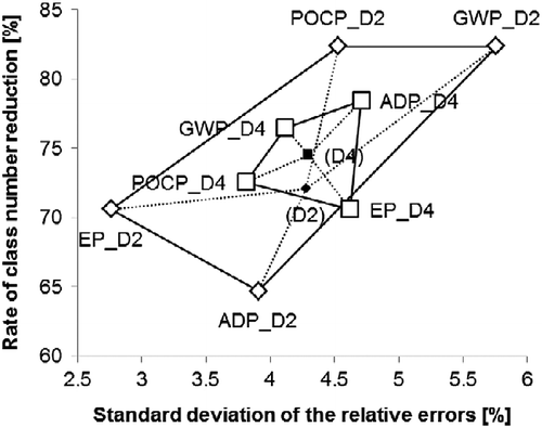
Second, the influences of the environmental impacts' values on the groups of dendrograms (D2) and (D4) are shown in Figure . Group (D2) where the life cycle steps are aggregated is represented with diamond-shaped areas; group (D4), where neither the life cycle steps, nor the environmental indicators are aggregated, is represented with squares. The environmental indicators of both groups form polygons. It can be observed that the area of the (D2)-polygon is higher than the area of the (D4)-polygon. It means that group (D2) is more sensitive to the environmental indicators than the dendrograms of group (D4); the variability of the errors and of the number of class is higher in group (D2) than in group (D4). Moreover, adding an environmental indicator and/or a life cycle step during the succession of learning phases will not have any influence on the already implemented ones for group (D4). Therefore, the method used to create the dendrograms of group (D4) is more advantageous than the one of group (D2). The dendrogram group (D4) is used in the subsequent parts of the paper.
The results shown in Table are focused on the manufacturing step and concern the clusters of cars obtained with the group of dendrogram (D4); the complete results are available in the Appendix Table 2. Here are comments for the four environmental impacts:
GWP: Hybrids are grouped together because of the high density of precious metals in the battery. The other groups are made by car classification: {B}, {C} and {C+; D; crossover};
Table 6 Description of the vehicles' clusters for the manufacturing step.
EP: The presence of leather in segment C or upper vehicles is the prime separation criterion; it can be assimilated to a high quality finish. The hybrid crossover {V10}, the heaviest car in the collection, is separated from the other hybrids that are grouped with the crossover that has the most leather {V9; V13; V17}. The seven-seat monospace {V8} is also separated. Mid quality finish segment B vehicles are grouped {V1; V2}, such as high quality finish segment D vehicles {V11; V12}. The high quality finish segment B vehicles are grouped with the mid finish quality monospace {V4; V14; V16}. All the segment C vehicles are grouped with the high quality finish segment B that has less leather {V3; V5; V6; V7; V15};
POCP: Same groups as GWP – manufacturing;
ADP: Hybrids are grouped together. Then groups are made per segment and per finish level. The high quality finish segment B vehicles are grouped with the mid quality finish segment C vehicles {V3; V4; V5; V6; V14}. The mid quality finish segment B vehicles are grouped together {V1; V2}, such as the high quality finish segment D {V11; V12}. The high quality finish segment C vehicle is grouped with the coupé-cabriolet and with the five-seat mid quality finish monospace {V7; V15; V16}. Lastly, the seven-seat monospace is grouped with the ICE crossover {V8; V9}.
The environmental indicators EP and POCP during the use step are depending on the emissions of the cars that are strongly and randomly varying from one car to another. The vehicle characteristics are insufficient to describe the groups of cars obtained for POCP during the use step. The classes obtained with (D4) may be described with five vehicle characteristics: segment, fuel type, finish, car's shape and consumption.
4.3. Influence of the thresholdϵmax on the boundary condition (C)
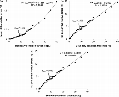
In this part, the evolution of the mean and the variability of the relative errors, and of the rate of class number reduction, as functions of the threshold ϵmax, is tested. Those three functions are, respectively, represented in Figure (a)–(c), and their nature is, respectively, polynomial, linear and logarithmic. We can therefore assume that changing the maximum value of errors is equivalent to changing the standard deviation.
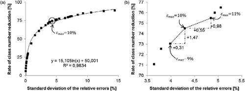
In Figure (a), the evolution of the rate of class number reduction is shown as a function of the standard deviation of the relative errors; its nature is logarithmic. The fewer the classes, the less dispersed and the closer to 0 the relative errors are. Figure (b) is a zoom of Figure (a) between ϵmax = 7% and ϵmax = 13%, with a constant step of 1%. The distance on the Y-axis between the points ϵmax = 9% and ϵmax = 10% is significant; it means that decreasing the threshold value to decrease the error variability leads to a higher number of classes. In the same way, the distance on the X-axis between the points ϵmax = 10% and ϵmax = 11% is significant; it means that increasing the threshold value to increase the rate of class number reduction leads to a higher variability of errors.
The following can be noticed:
A relevant benefit in terms of class number reduction is not made by allowing maximum relative errors higher than 10%.
The number of optimal classes increases from 52 to 55 while the threshold is only reduced by 1%, and the number of characteristics to identify the classes would increase.
4.4. Comparing results between different populations of the starting sample
In this third test, 10 simulations are made with different populations of 13 vehicles among the original 17. The 13 vehicles in the 10 simulations are the same as the original 17, but 4 vehicles are omitted for each simulation (1)–(10). These four omitted vehicles are given in Table .
Table 7 List of the omitted vehicles for the 10 simulations.
Results of the 10 simulations are represented on the graph of Figure . For nine simulations, the rate of class reduction is clearly lower and different from the original sample of 17 vehicles noted (0). It means that the number of classes is changing little and is between 46 and 50. In contrast, the standard deviations of the relative errors are dispersed between 4.02% and 4.79%. A rate of class reduction of 72%, the highest rate reached by the 10 simulations, is achieved by the simulation (4) for which all hybrids and the seven-seat monospace are excluded, bringing the number of optimal classes to 44.
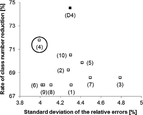
The groups of vehicles obtained with simulation (4) are similar to those obtained with (D4), by omitting vehicles V8, V10, V13 and V17. Nevertheless, for the manufacturing step, vehicle V9 is grouped with V11 and V12 on the indicator EP while they were separated with 17 vehicles (see Table ).
Table 8 Description of the vehicles' clusters for the manufacturing step of the simulation (4).
The groups of vehicles are stable and describable according to the vehicle characteristics of Table .
5. Discussion
The first test concerns the key question Q1. Classes obtained by the HAC and iterative process may be described with five vehicle characteristics: segment, fuel type, finish, car's shape and consumption. The car manufacturer's entire range of vehicles may be modelled. The boundary condition (C) ϵmax = 10% is a good compromise between a satisfying number of classes and a variability of the low relative errors, as shown in the third test.
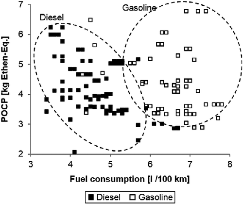
The classes deduced on the indicator POCP for the use phase are nevertheless less easy to identify because all vehicles used in this paper answer the same depollution standard Euro V. It is due to the difficulty to find a clear relationship between the pollutant emissions and a vehicle characteristics, as shown in Figure , where POCP values are calculated on the tank to wheels (TtW) step for 66 diesel vehicles and 96 gasoline vehicles (segments B, C, D and crossovers). The emissions were collected from the ADEME car comparison website for different versions of vehicles used in this paper. Two relatively separated clouds of points appear, but none of them have significant differences in terms of POCP values.
For each phase of the loop of learning, environmental indicators, life cycle steps and/or vehicles are added. On the one hand (key question Q3), it has been shown that for the first two cases, their influence on the rate of class reduction and on the variability of the relative errors is indeed strong. However, the optimal classes obtained for the existing life cycle steps and environmental indicators will not be modified. On the other hand (key question Q2), adding vehicles has little influence on the identification of optimal classes. The variation of the number of optimal classes will be small, leading to an increase of the rate of class number reduction. Nevertheless, the continuous improvement system is based on making LCA systematically whose results are integrated in the EMEECS building process for updating the environmental indicators scores of the models. If the company's strategy concerning LCA changes, the continuous improvement process is not assured.
The tool ‘Design Advisor’ developed by WorldAutoSteel has a strategy similar to TEEPI's strategy. The BOM of a vehicle is parameterized in such a way that a vehicle can be defined with a set of parameters (mass, dimensions, shape, etc.). Then, the user may define old and new modules, and relate the GWP impacts and the changing cost of the vehicle. Therefore, the philosophy of WorldAutoSteel is identical to that of EMEECS in TEEPI tool; but the strategies are diverging on the method of creating vehicle models: ‘Design Advisor’ creates a model from physical assumption, while EMEECS are directly built on previous LCA results. In the first tool, the range may nevertheless be larger than that represented by EMEECS and the user may define more precisely the vehicle. Lastly, ‘Design Advisor’ is dedicated to the GWP impacts while TEEPI deals with four environmental impacts, if not more.
6. Conclusions
The method of constructing EMEECS presented in this paper has two benefits: first, the contextual evaluation of an innovative sub-system is simplified by avoiding the evaluation of the entire future complex system, and second, in a long-term perspective, a loop of organizational learning is generated between the project, innovation and environment teams on the thematic eco-design, leading to a continuous improvement of the DIP. Engineers may make environmental evaluation of their innovation earlier in the DIP without having a complete description of the vehicle programme. An eco-design baseline integrated into the innovation quality process has been developed by the environment team in order to guarantee the use of TEEPI. All the innovations that may a priori have an environmental risk according to qualitative criteria defined in the eco-design baseline should be evaluated with TEEPI. Another publication concerning the use of TEEPI and its application to case studies is already planned.
We identify areas of further research that we intend to conduct. First, increasing the granularity level for representing models: these could be constructed over the sub-systems (body-in-white, engine, etc.) instead of the entire vehicle. A better accuracy could be reached without excessively increasing the number of characteristics needed to select the optimal classes. To do that, the vehicle functional scopes would be treated with HAC and the iterative process. Furthermore, it will be interesting to observe the influence of introducing vehicles of different generations
Second, only the environmental diagnostic phase of an eco-design method has been treated in this paper, and more particularly the creation of an environmental model. It would be necessary to propose improvement of tools to engineers: linking the environmental vehicle models to an improvement method would be really helpful for engineers in order to improve their innovations. For instance, TEEPI and the EMEECS would be linked with the method developed by Tchertchian, Yvars, and Millet (Citation2013) on using the constrained satisfaction problem in resolving an eco-design problem.
Disclosure statement
No potential conflict of interest was reported by the authors.
Notes
1.http://www.worldautosteel.org/projects/design-advisor/, accessed on 30 May 2013.
References
- Alonso, Juan C., JuliaDose, GünterFleischer, KateGeraghty, AndréGreif, JulioRodrigo, and Wulf-PeterSchmidt. 2006. “Electrical and Electronic Components in the Automotive Sector: Economic and Environmental Assessment.” The International Journal of Life Cycle Assessment12 (5): 328–335. 10.1065/lca2006.08.263.
- Andriankaja, Hery, GwenolaBertoluci, and DominiqueMillet. 2013. “Development and Integration of a Simplified Environmental Assessment Tool Based on an Environmental Categorisation Per Range of Products.” Journal of Engineering Design24 (1): 1–24. 10.1080/09544828.2012.665226.
- Bala, Alba, MarcoRaugei, GabrielaBenveniste, CristinaGazulla, and PereFullana-i-Palmer. 2010. “Simplified Tools for Global Warming Potential Evaluation: When ‘good Enough’ Is Best.” The International Journal of Life Cycle Assessment15 (5): 489–498. 10.1007/s11367-010-0153-x.
- Baumann, H., F.Boons, and A.Bragd. 2002. “Mapping the Green Product Development Field: Engineering, Policy and Business Perspectives.” Journal of Cleaner Production10 (5): 409–425. 10.1016/S0959-6526(02)00015-X.
- Beaume, Romain, Remi Maniak, and Christophe Midler. 2009. “Crossing Innovation and Product Projects Management: A Comparative Analysis in the Automotive Industry.” International Journal of Project Management, European Academy of Management (EURAM 2008) Conference EURAM 2008, 27 (2): 166–174. doi:10.1016/j.ijproman.2008.09.004.
- Bocken, N. M. P., J. M.Allwood, A. R.Willey, and J. M. H.King. 2011. “Development of an Eco-ideation Tool to Identify Stepwise Greenhouse Gas Emissions Reduction Options for Consumer Goods.” Journal of Cleaner Production19 (12): 1279–1287. doi:10.1016/j.jclepro.2011.04.009.
- Bohm, Matt R., Karl R.Haapala, KerryPoppa, Robert B.Stone, and Irem Y.Tumer. 2010. “Integrating Life Cycle Assessment Into the Conceptual Phase of Design Using a Design Repository.” Journal of Mechanical Design132 (9), 10.1115/1.4002152.
- Bovea, M. D., and V.Pérez-Belis. 2012. “A Taxonomy of Ecodesign Tools for Integrating Environmental Requirements into the Product Design Process.” Journal of Cleaner Production20 (1): 61–71. 10.1016/j.jclepro.2011.07.012.
- Collado-Ruiz, Daniel, and HesamedinOstad-Ahmad-Ghorabi. 2010. “Comparing LCA Results Out of Competing Products: Developing Reference Ranges from a Product Family Approach.” Journal of Cleaner Production18 (4): 355–364. 10.1016/j.jclepro.2009.11.003.
- Curzons, Alan D., ConcepciónJiménez-González, Ailsa L.Duncan, David J. C.Constable, and Virginia L.Cunningham. 2007. “Fast Life Cycle Assessment of Synthetic Chemistry (FLASCTM) Tool.” The International Journal of Life Cycle Assessment12 (4): 272–280. 10.1065/lca2007.03.315.
- Dlamini, Ndumiso G., KentaFujimura, EijiYamasue, HideyukiOkumura, and Keiichi N.Ishihara. 2011. “The Environmental LCA of Steel Vs HDPE Car Fuel Tanks with Varied Pollution Control.” The International Journal of Life Cycle Assessment30 (5): 410–419. 10.1007/s11367-011-0277-7.
- Finkbeiner, Matthias, and RüdigerHoffmann. 2006. “Application of Life Cycle Assessment for the Environmental Certificate of the Mercedes-Benz S-Class (7 Pp).” The International Journal of Life Cycle Assessment11 (4): 240–246. 10.1065/lca2006.05.248.
- Finnveden, Göran, Michael Z.Hauschild, TomasEkvall, JeroenGuinée, ReinoutHeijungs, StefanieHellweg, AnnetteKoehler, DavidPennington, and SangwonSuh. 2009. “Recent Developments in Life Cycle Assessment.” Journal of Environmental Management91 (1): 1–21. 10.1016/j.jenvman.2009.06.018.
- Gasafi, Edgar, and MarcelWeil. 2011. “Approach and Application of Life Cycle Screening in Early Phases of Process Design: Case Study of Supercritical Water Gasification.” Journal of Cleaner Production19 (14): 1590–1600. 10.1016/j.jclepro.2011.05.021.
- Geyer, Roland. 2008. “Parametric Assessment of Climate Change Impacts of Automotive Material Substitution.” Environmental Science & Technology15 (18): 6973–6979. 10.1021/es800314w.
- Graedel, T. E., T. Lanzano, W. Pott, and R. J. Araujo. 2005. Multiscale Life-Cycle Assessment. Yale School of Forestry & Environmental Studies. http://environment.research.yale.edu/documents/downloads/v-z/wp_6_multiscale_lifecycle.pdf.
- Hastie, Trevor, Robert Tibshirani, and Jerome Friedman. 2001. The Elements of Statistical Learning. Vol. 1. New York: Springer. http://www-stat.stanford.edu/∼tibs/book/preface.ps.
- Jacqueson, Loïc, Dominique Millet, and Ameziane Aoussat. 2001. “Integration of the Environment in the Product Design Process: Proposal for a Learning Driving Tool.” In International Symposium on Management of the Indutrial and Corporate Knowledge, ISMICK ‘01, Compiègne, France, 22–24. http://citeseerx.ist.psu.edu/viewdoc/download?doi = 10.1.1.16.9081&rep = rep1&type = pdf.
- Jacquemin, Leslie, Pierre-YvesPontalier, and CarolineSablayrolles. 2012. “Life Cycle Assessment (LCA) Applied to the Process Industry: a Review.” The International Journal of Life Cycle Assessment17 (8): 1028–1041. 10.1007/s11367-012-0432-9.
- Johansson, G., A.Greif, and G.Fleischer. 2007. “Managing the Design/Environment Interface: Studies of Integration Mechanisms.” International Journal of Production Research45 (18–19): 4041–4055. 10.1080/00207540701474823.
- Johansson, Glenn, and ThomasMagnusson. 2006. “Organising for Environmental Considerations in Complex Product Development Projects: Implications from Introducing a ‘Green’ Sub-project.” Journal of Cleaner Production14 (15–16): 1368–1376. 10.1016/j.jclepro.2005.11.014.
- Karlsson, Reine, BengtSteen, and AgnetaWendel. 1997. “EPS as a Life Cycle Oriented System Assessment Tool to Facilitate Industrial Learning about Relations to the Environment.” In The 15th International Conference of the System Dynamics Society, Istanbul, Turkey, edited by YamanBarlas, Vedat G.Diker, and SeckinPolat, 61–68. http://www.systemdynamics.org/conferences/1997/karlsson.pdf.
- Keoleian, G. A., and K.Kar. 2003. “Elucidating Complex Design and Management Tradeoffs through Life Cycle Design: Air Intake Manifold Demonstration Project.” Journal of Cleaner Production11 (1): 61–77. 10.1016/S0959-6526(02)00004-5.
- Keoleian, Gregory A., SabrinaSpatari, Robb T.Beal, Robert D.Stephens, and Ronald L.Williams. 1998. “Application of Life Cycle Inventory Analysis to Fuel Tank System Design.” The International Journal of Life Cycle Assessment3 (1): 18–28. 10.1007/BF02978446.
- Le Pochat, Stéphane, GwenolaBertoluci, and DanielFroelich. 2007. “Integrating Ecodesign by Conducting Changes in SMEs.” Journal of Cleaner Production15 (7): 671–680. 10.1016/j.jclepro.2006.01.004.
- Millet, Dominique, LuigiBistagnino, RogerCamous, and AmezianeAoussat. 2004. “Integration of New Dimensions in Design Process.” In Methods and Tools for Co-operative and Integrated Design, edited by SergeTichkiewitch and DanielBrissaud, 209–222. New York: Springer. http://link.springer.com/chapter/10.1007/978-94-017-2256-8_18.
- Millet, Dominique, LuigiBistagnino, C.Lanzavecchia, RogerCamous, and TiiuPoldma. 2007. “Does the Potential of the Use of LCA Match the Design Team Needs?” Journal of Cleaner Production15 (4): 335–346. 10.1016/j.jclepro.2005.07.016.
- Muñoz, Ivan, JoanRieradevall, XavierDomènech, and CristinaGazulla. 2005. “Using LCA to Assess Eco-design in the Automotive Sector: Case Study of a Polyolefinic Door Panel (12 Pp).” The International Journal of Life Cycle Assessment11 (5): 323–334. 10.1065/lca2005.05.207.
- Nakano, Katsuyuki, and MasahikoHirao. 2011. “Collaborative Activity with Business Partners for Improvement of Product Environmental Performance Using LCA.” Journal of Cleaner Production19 (11): 1189–1197. 10.1016/j.jclepro.2011.03.007.
- Oltra, Vanessa, and MaïderSaint Jean. 2009. “Sectoral Systems of Environmental Innovation: An Application to the French Automotive Industry.” Technological Forecasting and Social Change76 (4): 567–583. 10.1016/j.techfore.2008.03.025.
- Ostad-Ahmad-Ghorabi, Hesamedin, and DanielCollado-Ruiz. 2011. “Tool for the Environmental Assessment of Cranes Based on Parameterization.” The International Journal of Life Cycle Assessment6 (5): 392–400. 10.1007/s11367-011-0280-z.
- Poudelet, Victor, Julie-AnneChayer, ManueleMargni, RobertPellerin, and RéjeanSamson. 2012. “A Process-based Approach to Operationalize Life Cycle Assessment Through the Development of an Eco-design Decision-support System.” Journal of Cleaner Production33: 192–201. 10.1016/j.jclepro.2012.04.005.
- Puri, Prateek, PaulCompston, and VictorPantano. 2009. “Life Cycle Assessment of Australian Automotive Door Skins.” The International Journal of Life Cycle Assessment14 (5): 420–428. 10.1007/s11367-009-0103-7.
- Ribeiro, Catarina, José V.Ferreira, and PauloPartidário. 2006. “Life Cycle Assessment of a Multi-material Car Component.” The International Journal of Life Cycle Assessment12 (5): 336–345. 10.1065/lca2006.12.304.
- Rio, Maud, TatianaReyes, and LionelRoucoules. 2013. “Toward Proactive (eco)design Process: Modeling Information Transformations Among Designers Activities.” Journal of Cleaner Production39: 105–116. 10.1016/j.jclepro.2012.07.061.
- Schmidt, Wulf-Peter. 2006. “Life Cycle Tools Within Ford of Europe's Product Sustainability Index. Case Study Ford S-MAX & Ford Galaxy (8 Pp).” The International Journal of Life Cycle Assessment11 (5): 315–322. 10.1065/lca2006.08.267.
- Schmidt, Wulf-Peter, and Hans-MartinBeyer. 1999. “Environmental Considerations on Battery-Housing Recovery.” The International Journal of Life Cycle Assessment4 (2): 107–112. 10.1007/BF02979410.
- Schmidt, Wulf-Peter, ElisabethDahlqvist, MatthiasFinkbeiner, StephanKrinke, SilviaLazzari, DirkOschmann, SophiePichon, and ChristianThiel. 2004. “Life Cycle Assessment of Lightweight and End-of-life Scenarios for Generic Compact Class Passenger Vehicles.” The International Journal of Life Cycle Assessment9 (6): 405–416.
- Schweimer, Georg W., and Marcel Levin. 2000. “Life Cycle Inventory for the Golf A4.Volkswagen AG.” http://www.volkswagenag.com/vwag/vwcorp/info_center/en/publications/2007/01/Golf_A4__Life_Cycle_Inventory.-bin.acq/qual-BinaryStorageItem.Single.File/golfa4_english.pdf.
- Sousa, Ines, and DavidWallace. 2006. “Product Classification to Support Approximate Life-cycle Assessment of Design Concepts.” Technological Forecasting and Social Change73 (3): 228–249. 10.1016/j.techfore.2004.03.007.
- Tchertchian, Nicolas, YvarsPierre-Alain, and MilletDominique. 2013. “Benefits and Limits of a Constraint Satisfaction Problem/Life Cycle Assessment approach for the Ecodesign of Complex Systems: A Case Applied to a Hybrid Passenger Ferry.” Journal of Cleaner Production42: 1–18. 10.1016/j.jclepro.2012.10.048.
- Tingström, Johan, and ReineKarlsson. 2006. “The Relationship Between Environmental Analyses and the Dialogue Process in Product Development.” Journal of Cleaner Production14 (15–16): 1409–1419. 10.1016/j.jclepro.2005.11.012.

