Abstract
Due to energy crisis and shortage of fossil fuel, there is a growing interest in alternative fuel for internal combustion engine. Producer gas presents a very promising alternative fuel to diesel since it is a renewable and clean burning fuel having properties similar to that of diesel. In this study, a twin cylinder dual fuel diesel engine is experimentally optimized for maximum diesel saving and lower emissions, without any undue vibration of engine using woody biomass producer gas. The test is carried out to study the performance and emission parameters of the engine in diesel mode and dual fuel mode at different gas flow rates under different load conditions. The study reveals that maximum diesel savings is found to be 83% at optimum gas flow rate and 8 kW load. Carbon monoxide, hydrocarbon and carbon dioxide emissions in dual fuel mode were higher compared with diesel mode at all test ranges. However, the main pollutants, such as nitrogen oxide and smoke, decrease substantially in the dual fuel mode compared with the diesel mode. Lower brake thermal efficiency and higher brake-specific energy consumption as well as exhaust gas temperature are observed in dual fuel mode compared with diesel mode.
1. Introduction
Due to higher brake thermal efficiency (BTE) of the diesel engine compared with the gasoline engine, it is quite popular in agriculture and transport sector. Since India is an agricultural country, huge amount of diesel fuel is consumed in the agriculture sector. Due to rapid depletion of diesel fuel, its rising prices and hazardous emissions from vehicles, an alternative fuel for diesel is critically important for our nation's economic growth and security. The complete substitution of diesel for transport and agriculture sector is the biggest challenge for India. Keeping this in view, more interest is dedicated to carry out research work to discover the viable alternative fuel for diesel engine in India. Biomass-derived producer gas can be used as an alternative fuel for diesel engine due to their eco-friendly nature (Nwafor Citation2000a, Citation2000b). Producer gas when burnt produces insignificant SOx and little oxide of nitrogen (NOx), the main constituent of acid rain and smog, than fossil fuel (Henham and Makkar Citation1998). However, due to higher octane number of the producer gas, it cannot operate in diesel engines with the help of small amount of injected pilot fuel. Hence, a diesel engine needs to be dual fuelled.
Power derating is the major problem with producer gas operation in a gas engine. A power drop of 40–70% can be expected as mentioned in the literature (Kaupp and Goss Citation1984; Vyarawalla et al. Citation1984; Parikh et al. Citation1989). Due to very high derating nature, retrofit application of existing SI engine is not much attractive. From fuel flexibility and derating point of view, dual fuel engine can be highly used for decentralized power generation and agriculture purpose. Engine modification of existing diesel engine into dual fuel mode operation of producer gas is very easy, and power derating is limited to 20–30%. In the literature, it is mentioned that diesel savings up to 70–90% occur in dual fuel operation using renewable alternative fuels (Bhattacharya, Hla, and Pham Citation2001; Uma, Kandpal, and Kishore Citation2004; Ramadhas, Jayaraj, and Muraleedharan Citation2006). The development of two gas carburetors with 45° and 90° gas entries to enable effective mixing of air and producer gas is studied by Banapurmath et al. (Citation2012). In their work, they reported that the maximum BTE was found to be 22.75% when using carburetor with 90° gas entries in comparison with 20% in carburetor with 45° gas entries. One of the review articles regarding the improvement of producer gas quality in downdraft biomass gasifier and its application in internal combustion engine is reported by Martinez et al. (Citation2012). They reported that producer gas quality can be influenced by the effect of particle size, moisture content and air/fuel equivalence ratio. The fuel used for dual fuelling includes hydrogen, LPG, CNG and alcohols (Senthil Kumar, Ramesh, and Nagalingum Citation2003; Alam et al. Citation2001). Due to lower running cost and use of different alternative fuel sources in dual fuel mode, it attracts many investigators to use this engine in different areas. The current dual fuel engine can be operated interchangeably, either on gaseous fuel with diesel pilot ignition or wholly on liquid fuel injection as a diesel engine. Due to this switching over mechanism from dual fuel mode to single mode operation in a dual fuel engine, it tends to retain most of the positive features of diesel operation (Badr, Karim, and Liu Citation1999). The main objective of using dual fuel engine is to reduce NOx and particulate emission. In case of diesel engine, it is difficult to reduce simultaneously both NOx and smoke due to the trade-off curve between NOx and smoke. One suitable method is to solve this problem by using alternative oxygenated fuel which provides more oxygen for combustion.
Gasification is the process of conversion of solid/liquid biofuels into gaseous fuel in a gasifier by pyrolysis process at high temperature. The conversion of wood is done using a gasifier to produce producer gas, which is a mixture of carbon monoxide (CO), hydrogen, carbon dioxide (CO2), methane and nitrogen. The typical compositions of producer gas generated from babul wood with desired moisture content were measured by using the microprocessor-based gas chromatograph (model no. 2010) supplied by Chromatography and Instruments Company Pvt. Ltd Baroda (see Table ). The properties of test fuels are given in Table .
Table 1 Composition of producer gas.
Table 2 Properties of test fuels.
In the literature, it is reported that wood producer gas single cylinder dual fuel diesel engine can run efficiently up to 50–60% of the full load, after which the performance is inferior (Ramadhas, Jayaraj, and Muraleedharan Citation2008). Many investigators in their research work mentioned that maximum diesel savings occurs up to 71% (Banapurmath et al. Citation2009), 64% (Sonaton, Das, and Jash Citation2004), 72% (Ramadhas, Jayaraj, and Muraleedharan Citation2006) and 75% (Dasappa and Sridhar Citation2011) using wood producer gas at optimum load condition.
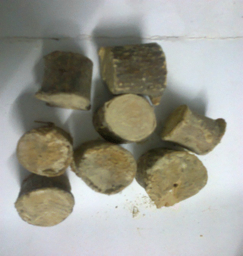
This work is an effort to evaluate the feasibility of producer gas generated from babul wood and the effect of its flow rate on the performance of a twin cylinder four-stroke diesel engine for maximum replacement of diesel fuel and without any undue vibration of the engine. The sample of wood pieces is shown in Figure .
2. Characteristics of biomass used
Woody biomass is a well-known suitable and traditional fuel in India where generation of heat is necessary. The wood has higher calorific value and low ash content of wood. In this study for gasifier feedstock, small pieces of babul wood of approximately 25 mm length and 25 mm diameter were generated in our laboratory and suitably used. For obtaining better quality and higher calorific value of gas, the moisture content of the wood used was maintained at less than 20%. The ultimate and approximate analysis of babul wood (Prosopis juliflora) under wet basis (wb) and dry basis (db) is shown in Table (Panwar and Salvi Citation2011). The average gas calorific value is found to be 4186 kJ/m3 in the reported work.
Table 3 Ultimate and approximate analysis of biomass feed stock babul wood.
3. Test procedure and methodology
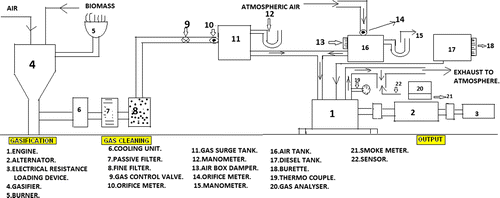
The schematic diagram of the experimental set-up is shown in Figure . The experimental set-up consists of a twin cylinder four-stroke diesel engine operated in dual fuel mode coupled with generator and electrical resistance type loading devices supplied by Prakash Diesels Pvt., Ltd Agra, a downdraft type biomass gasifier, gas cooler, gas filter supplied by Ankur Scientific Energy Technology Pvt. Ltd, Baroda. The detailed specifications of the engine and downdraft woody biomass gasifier are given in Tables and , respectively. The error in the flow measurement device of producer gas and air lies within ± 2%. The biomass is loaded from the top of the gasifier and ash is removed at a regular interval. The partial combustion of biomass in the gasifier reactor is converted into high temperature producer gas, which enters the gas cooler. The moisture, tar and dust particle are removed by passing through two sets of filters. At the outlet of the filter pipe, a mechanical valve is provided to control the gas flow rate. For gas flow measurement, an orifice meter and a manometer is connected to surge tank. Manometers are used to measure the air and gas flow separately. The uncertainty of calibrated orifice meters used for both gas and airflow measurement are found to be ± 1.86% and ± 1.90%, respectively. The producer gas and air are mixed in the intake pipe and then the mixture enters the engine cylinder. The engine is always operated at its rated speed of 1500 rpm, injection timing of 23˚ before top dead centre (BTDC) and injection pressure of 220 bar. The tests are carried out in fossil diesel mode and in dual fuel mode operation under variable gas flow rates such as 0, 10.74, 15.21, 18.61 and 21.49 kg/h under different load conditions of 0, 2, 4, 6, 8 and 10 kW. In dual fuel mode operation, the gas flow rate is measured by using an orifice meter and manometer attached to the gas surge tank. For a particular gas flow rate, the head difference in the manometer is kept to be constant by using a mechanical control valve. Therefore, for different gas flow rates, the head difference is varied by rotating the control valve. However, the injected diesel flow rate is not maintained constant. The temperature of combustion gas before entering the cooling system is measured by using a thermocouple and is found to be 458°C, and after cooling and cleaning, it is found to be 37°C. Similarly, during trial run, the indicative pressure drop in the nozzle at rated flow is found to be 20 mm of water column and indicative pressure drop in the gasifier is found to be 40–45 mm of water column at rated gas flow rate.
Table 4 Test engine specifications.
Table 5 Specification of down draft gasifier.
The performance and emission studies are observed under different substitution of gas–air ratio at different load conditions. AVL Digas 444 and smoke meter (model no. AVL 437 C) with accuracy ± 1% is used to measure exhaust gas emission parameters and smoke opacity, respectively. The parameters such as CO, hydrocarbon (HC) and CO2 are measured by using the non-dispersive infrared method, and NOx and O2 are measured by using electrochemical method.
4. Result and discussions
4.1 Brake thermal efficiency
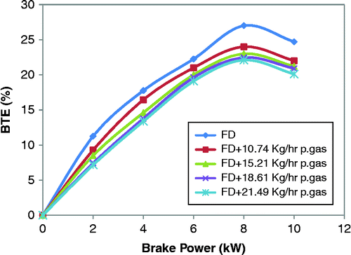
Figure shows the variations in BTE under different conditions of gas flow rate and load for both modes of operations. It indicates that BTE in dual fuel mode is always lower than that of diesel mode under all test ranges. This is because of lower calorific value and slow burning nature of the producer gas. Again, with increase in gas flow rate in dual fuel mode, BTE decreases. This is attributed to decrease in fresh air percentage and calorific value in the mixture with increase in gas flow rate. The maximum BTE at 8 kW load is found to be 27.5% in diesel mode and 24%, 23%, 22.57% and 22.22%, respectively, in case of dual fuel mode operated on different gas flow rates of 10.74, 15.21, 18.61 and 21.49 kg/h. From the result, it is evident that the maximum BTE of the engine operated in dual fuel mode at optimum gas flow rate is reduced by 5.28% compared with normal diesel mode. However, the percentage decrease in BTE with subsequent increase in gas flow rates from 0 to 10.74 kg/h, 10.74 to 15.21 kg/h, 15.21 to 18.61 kg/h and 18.61 to 21.49 kg/h in dual fuel mode operation is found to be 11.2%, 16.5%, 16.86% and 17.36%, respectively, at full load condition compared with diesel mode.
4.2 Brake-specific energy consumption
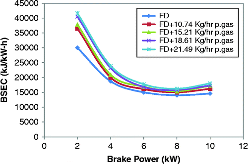
The variations in brake-specific energy consumption (BSEC) with different conditions of load and gas flow rate for both modes of operation are shown in Figure . It is observed that with increase in load up to 8 kW, BSEC decreases for both modes of operations beyond which it increases. This is because with increase in load up to 8 kW, combustion temperature of the cylinder charge increases resulting in better combustion. But at full load, it increases due to lower combustion efficiency as a result of insufficient air. On comparing dual fuel mode at optimum gas flow rate with diesel mode, it is found that the BSEC in dual fuel mode is 15.71% higher than diesel mode at 8 kW load. This is due to lower energy content and adiabatic flame velocity of producer gas compared with diesel. Again, it is evident that with increase in gas flow rates, BSEC increases at all load conditions. At full load condition, with subsequent increase in gas flow rates from 0 to 10.74 kg/h, 10.74 to 15.21 kg/h, 15.21 to 18.61 kg/h and 18.61 to 21.49 kg/h the percentage increase in BSEC is found to be 11.64%, 18.15%, 18.49% and 21.2%, respectively, compared with diesel mode.
4.3 Exhaust gas temperature
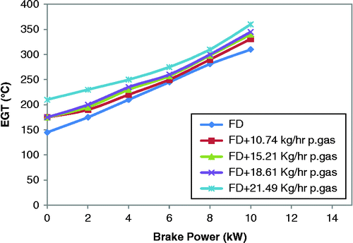
The variations in exhaust gas temperature (EGT) for both modes of operation under different conditions of load and gas flow rate are depicted in Figure . It is found that the EGT for both modes of operation increases with increase in load. This is due to increase in total energy input to the engine with load. Also, EGT for dual fuel mode is higher than that of diesel mode at all test ranges. This is an explanation of more energy input into the engine and higher delay period of producer gas resulting in higher energy release after combustion phase. Again, with increase in gas flow rate in dual fuel mode, EGT increases due to higher energy input to the engine. The highest value of EGT is found to be 360°C in dual fuel mode under maximum gas flow rate compared with 310°C in case of diesel mode at full load condition. However, at full load condition, with increase in gas flow rates from 0 to 10.74 kg/h, 10.74 to 15.21 kg/h, 15.21 to 18.61 kg/h and 18.61 to 21.49 kg/h the percentage increase in EGT is found to be 8%, 9.5%, 11.2% and 16.1%, respectively, compared with diesel mode.
4.4 CO emission
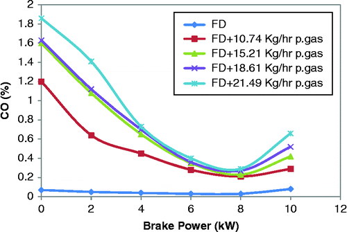
Figure illustrates the variations in CO for both modes of operation under different conditions of load and gas flow rate. It is observed that the CO emission in dual fuel mode operation at all test ranges is higher than in the diesel mode. This is an indication of incomplete combustion and presence of CO in producer gas composition in dual fuel mode. The other reason is the lower calorific value and adiabatic flame temperature of the producer gas (Banapurmath et al. Citation2009). However, with increase in load, CO emission decreases for both modes of operation due to better combustion as a result of higher charge temperature. But at highest load, it decreases on account of rich mixture. Moreover, with increases in gas flow rate, CO emission increases in dual fuel mode due to decrease in air percentage in mixture. At full load condition, the percentage increase in CO emission with increase in gas flow rate from 0 to 10.74 kg/h, 10.74 to 15.21 kg/h, 15.21 to 18.61 kg/h and 18.61 to 21.49 kg/h is found to be 2.62%, 4.25%, 5.5% and 7.25%, respectively, compared with diesel mode.
4.5 Hydrocarbon emission
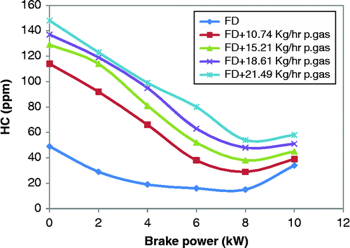
Figure shows the variations in HC emission for both modes of operation at different conditions of load and gas flow rate. The HC emission trends are similar to CO emission for both modes of operation. At no load and highest load conditions, HC emissions are found to be higher as compared with higher load conditions. The reason is the lower cylinder charge temperature and fuel richness which cause incomplete combustion at no load and highest load condition, respectively, which enhances the HC emission. However, at higher load, it decreases due to oxidation of HC at higher charge temperature. It is found that the engine operated in dual fuel mode at optimum gas flow rate produces 70.5% higher HC emission compared with normal diesel mode. Similarly, with increase in gas flow rate, HC emission increases due to lower combustion temperature, slow burning rate of producer gas and decrease in airflow rate. At 8 kW load, the percentage increase in HC emission with increase in gas flow rate from 0 to 10.74 kg/h, 10.74 to 15.21 kg/h, 15.21 to 18.61 kg/h and 18.61 to 21.49 kg/h is found to be 11.5%, 46.1%, 84.6% and 111.5%, respectively, compared with diesel mode.
4.6 CO2 emission
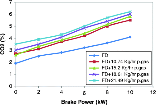
Figure demonstrates the variations in CO2 emission for both modes of operation under different conditions of load and gas flow rate. It is found that with increase in load, CO2 emission increases for both modes of operation. This is due to oxidation of CO into CO2 at higher charge temperature. However, in comparison with diesel and dual fuel mode, CO2 emission is more in the case of dual fuel mode. Since the producer gas is a mixture of CO and CO2, its combustion increases the CO2 emission (Ramadhas, Jayaraj, and Muraleedharan Citation2006). Again, with increase in gas flow rate, CO2 emission increases. At full load condition, the percentage increase in CO2 emission with increase in gas flow rate from 0 to 10.74 kg/h, 10.74 to 15.21 kg/h, 15.21 to 18.61 kg/h and 18.61 to 21.49 kg/h is found to be 34.47%, 41.8%, 46.69% and 51.5%, respectively, compared with diesel mode.
4.7 NOx emission
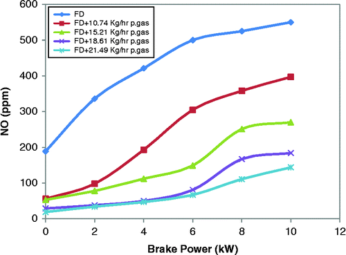
NOx is the most vital factor for diesel engine emission. Figure shows that the NOx emission in diesel mode is higher than that of dual fuel mode under all load conditions. This is on account of lower adiabatic flame temperature and absence of organic nitrogen in producer gas (Banapurmath et al. Citation2009) in dual fuel mode. Also, with increase in load, NOx emission increases for both modes of operation due to increases in combustion temperature as a result of higher energy input. However, with increase in gas flow rate, NOx emission decreases. At full load condition, the percentage decrease in NOx emission with increase in gas flow rate from 0 to 10.74 kg/h, 10.74 to 15.21 kg/h, 15.21 to 18.61 kg/h and 18.61 to 21.49 kg/h is found to be 27.81%, 50.9%, 66.5% and 73.81%, respectively, compared with diesel mode.
4.8 Smoke opacity
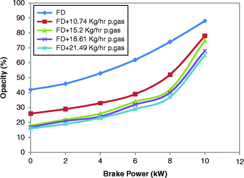
The variations in smoke opacity with different loads of the engine for various gas flow rates in both modes of operation are shown in Figure . The figure reveals that the smoke opacity in dual fuel mode is lower compared with the diesel mode under all load conditions. This is due to clean burning of producer gas and decrease in percentage of injected pilot fuel in dual fuel mode. The other reason is the absence of aromatic and sulphur content in producer gas, which is the main factor of smoke formation. Moreover, with increase in gas flow rate, smoke opacity decreases. At full load condition, the percentage decrease in smoke opacity with increase in gas flow rate from 0 to 10.74 kg/h, 10.74 to 15.21 kg/h, 15.21 to 18.61 kg/h and 18.61 to 21.49 kg/h is found to be 11.3%, 14.7%, 22.7% and 26.1%, respectively, compared with diesel mode. Again, with increase in load, smoke opacity increases for both modes of operation. This is because, with increase in load, diesel percentage in both modes increases and fresh air decreases, which causes higher smoke emission.
4.9 Diesel savings
The diesel savings in dual fuel mode operation is calculated as
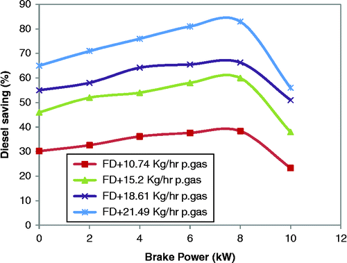
Figure explains the percentage of diesel savings in dual fuel mode at different flow rates under varying loads. With increase in producer gas flow rate, diesel savings increase. It is observed that the maximum diesel savings have gone up to 83% at 8 kW load under maximum gas flow rate. Similarly, minimum diesel savings of 38.4% occur at same load condition for minimum gas flow rate. The decrease in diesel savings is found under both minimum and maximum load conditions. This decrease in diesel savings may be attributed to low combustion temperature at minimum load and insufficient fresh air at maximum load, which causes incomplete combustion.
5. Conclusions
This study proves that the diesel engine has the capability to run successfully without any undue vibration of the engine in dual fuel mode using woody biomass producer gas at an optimum gas flow rate of 21.49 kg/h. The important findings are as follows:
The engine performance decreases in the dual fuel mode compared with the diesel mode at all test conditions.
The maximum BTE of the engine operated in dual fuel mode at optimum gas flow rate is reduced by 5.28% compared with normal diesel mode at 8 kW load.
The BSEC in dual fuel mode at optimum gas flow rate is found to be 15.71% higher than diesel mode at 8 kW load.
The EGT in dual fuel mode at optimum gas flow rate is dropped by 50°C compared with normal diesel mode.
NOx and smoke emissions at different gas flow rates in dual fuel mode operation are lower compared with diesel mode.
At full load condition, the percentage decrease in NOx emission with increase in gas flow rate from 0 to 10.74 kg/h, 10.74 to 15.21 kg/h, 15.21 to 18.61 kg/h and 18.61 to 21.49 kg/h is found to be 27.81%, 50.9%, 66.5% and 73.81%, respectively, compared with diesel mode.
Similarly, under the above-mentioned test conditions, the percentage decrease in smoke opacity with increase in gas flow rate is found to be 11.3%, 14.7%, 22.7% and 26.1%, respectively, compared with diesel mode.
At 8 kW load, the percentage increase in HC emission with increase in the above-mentioned gas flow rate is found to be 11.5%, 46.1%, 84.6% and 111.5%, respectively, compared with diesel mode.
At full load and above-mentioned gas flow rate condition, the percentage increase in CO emission is found to be 2.62%, 4.25%, 5.5% and 7.25%, respectively, compared with diesel mode. However, under the same test condition the percentage increase in CO2 emission is found to be 34.47%, 41.8%, 46.69% and 51.5%, respectively, compared with diesel mode.
The maximum diesel saving is observed to be 83% at 8 kW of the engine load in dual fuel mode at optimum gas flow rate.
Producer gas can act as a knock suppressor due to the presence of inert gases such as 50% N2 and 10 ± 3% CO2 in its composition, which is beneficial in cases where high compression ratio engines are employed.
After a careful analysis of the above-mentioned study, it is found that the dual fuel mode operation shows lower performance and higher emission of HC, CO and CO2 compared with diesel mode due to poor combustion performance of the producer gas in the engine. Hence, it is suggested that the improvement of combustion quality of producer gas by using some technique or modification of the engine can be looked upon as future work.
Acknowledgements
The authors are thankful to the Department of Mechanical Engineering, SOA University, India for providing the experimental set-up to complete this research work.
References
- Alam, M., S. Goto, K. Sugiyama, and M. Kajiwara. 2001. Performance and Emission of a DI Diesel Engine Operated with LPG and Ignition Improving Additives, SAE Technical Paper 2001-01-3680.
- Badr, O., G. A. Karim, and B. Liu. 1999. “An Examination of the Flame Spread Limits in a Dual Fuel Engine.” Applied Thermal Engineering 19 (10): 1071–1080.
- Banapurmath, N. R., P. G. Tewari, V. S. Yaliwal, and R. S. Hoshmath. 2012. “Life Improvement Program of Producer Gas–Biodiesel Operated Dual Fuel Engine.” International Journal of Sustainable Engineering 5 (4): 350–356.
- Banapurmath, N. R., P. G. Tewari, V. S. Yaliwal, S. Kambalimath, and Y. H. Basavarajappa. 2009. “Combustion Characteristics of a 4-Stroke CI Engine Operated on Honge Oil, Neem Oil and Rice Bran Oils When Directly Injected and Dual Fuelled with Producer Gas Induction.” Renewable Energy 34: 1877–1884.
- Bhattacharya, S. C., S. S. Hla, and H. L. Pham. 2001. “A Study on a Multi-Stage Hybrid Gasifier Engine System.” Biomass and Bioenergy 21: 445–460.
- Dasappa, H., and H. V. Sridhar. 2011. “Performance of Diesel Engine in Dual Fuel Mode Using Producer Gas for Electricity Power Generation.” International Journal of Sustainable Energy, iFirst 1–16.
- Henham, A., and M. K. Makkar. 1998. “Combustion of Simulated Biogas in a Dual-Fuel Diesel Engine.” Energy Conversion Management 39: 2001–2009.
- Kaupp, A., and J. R. Goss. 1984. Small Scale Gas Producer Engine Systems. Braunschweig: Friedr Vieweg and Sohn.
- Martinez, J. D., K. Mahkamov, R. V. Andrade, and E. E. S. Lora. 2012. “Syngas Production in Downdraft Biomass Gasifiers and Its Application Using Internal Combustion Engines.” Renewable Energy 38: 1–16.
- Nwafor, O. M. I. 2000a. “Effect of Choice of Pilot Fuel on the Performance of Natural Gas in Diesel Engine.” Renewable Energy 21: 495–504.
- Nwafor, O. M. I. 2000b. “Effect of Advanced Injection Timing on the Performance of Natural Gas in Diesel Engine.” Sadhana 25 (1): 11–20.
- Panwar, N. L., and B. L. Salvi. 2011. “Experimental Investigation of Producer Gas Burner for Thermal Application.” International Journal of Sustainable Energy 30 (6): 376–384.
- Parikh, P. P, A. G. Bhave, D. V Kapse, and S. Karinka. 1989. “Study of Thermal and Emission Performance of Small Gasifier Dual Fuel Engine System.” Biomass 19: 75–97.
- Ramadhas, A. S., S. Jayaraj, and C. Muraleedharan. 2006. “Power Generation Using Coir-Pith and Wood Derived Producer Gas in Diesel Engine.” Fuel Processing Technology 87: 849–853.
- Ramadhas, A. S., S. Jayaraj, and C. Muraleedharan. 2008. “Dual Fuel Mode Operation in Diesel Engine Using Renewable Fuels: Rubber Seed Oil and Coir-Pith Producer Gas.” Renewable Energy 33: 2077–2083.
- Senthil Kumar, M., A. Ramesh, and B. Nagalingum. 2003. “Use of Hydrogen to Enhance the Performance of a Vegetable Oil Fuelled Compression Ignition Engine.” International Journal of Hydrogen Energy 28: 1143–1154.
- Sonaton, G., T. K. Das, and T. Jash. 2004. “Sustainability of Decentralized Wood Fuel-Based Power Plant: An Experience in India.” Energy 29: 155–166.
- Uma, R., C. T. Kandpal, and N. V. V. Kishore. 2004. “Emission Characteristics Electricity Generation System in Diesel Alone and Dual Fuel Modes.” Biomass and Bioenergy 27: 195–203.
- Vyarawalla, F., P. P. Parikh, C. H. Dak, and C. B. Jain. 1984. “Utilization of Biomass for Motive Power Generation: Gasifier Engine System.” Biomass 3: 227–242.

