Abstract
This manuscript proposes a hybrid simulation model of discrete and continuous modes, designed to predict energy consumption and flows within an automotive production facility. The simulation integrates sub-models for the plant stations and energy management center based on regression analysis of two-year data, forecasting, and physical modelling. The hybrid simulation is developed to account for the energy consumed in manufacturing, air-tempering, and in maintaining equipment with large thermal inertia in an idle-state. The model is applied in twofold; a Daily volume production and a Sequence record and delay modes. The results are found in agreement with plant-recorded data.
1. Introduction
Energy consumption cost American vehicle production facilities around $3.6 billion in 1999. However, this number represented a small percentage of the total output (vehicles sold) that year, nearly $350 billion, Galitsky and Worrell (Citation2003). Thus, less emphasis has been placed on energy efficiency. However, reducing the energy cost is not only considered product-quality and production-yield neutral, but also can reduce the uncertainty in production costs and may result in more predictable earnings' estimates. Studies from the American Council for an Energy Efficient Economy ACEEE by Patil, Seryak, and Kissock (Citation2003), classify the industrial benchmarking efforts for energy-efficiency into two main streams; the Long-term Industrial Energy Forecasting (LIEF) methods and the Environmental Protection Agency (EPA) Energy Performance Indicators (EPI). In essence, LIEF assumes that the difference between average performers and best practices is based on energy prices, while EPI assumes the difference to be of technical nature, Omar (Citation2011). Furthermore, the EPI stochastic modelling can provide energy consumption data for large number of industrial manufacturing facilities in the US.
The energy consumption during the manufacturing process can be perceived from three aspects. The first is in maintaining the working environment of the plant (e.g. ventilation, illumination and air-conditioning), which is referred to as the ‘plant’ level consumption as in (Galitsky and Worrell Citation2003; Boyd Citation2005; U.S. DOE (U.S. Department of Energy) Citation2011, 74–78). The second is the energy used for the actual production; i.e. running the equipment and machinery; this part can be termed the ‘process’ level consumption as in Rahimifard, Seow, and Childs (Citation2010). The third type of energy consumption is the wastage of energy through transformations (fossil into thermal into electrical, etc.) and transmission. This kind of consumption will be referred to, in this research, as the ‘transformation efficiency’ level. Hence, the evaluation of the plant energy performance should capture the energy flow, energy connection dynamics, and the energy cost at these three levels, Andreassi et al. (Citation2009). Some of the most prevailing approaches to achieve such evaluation or accounting include; regression analysis, fuzzy logic, Mills et al. (Citation2008), and energy simulation as in Devoldere et al. (Citation2007). In terms of comprehensiveness and energy visualization, energy simulation is a sensible selection.
This manuscript discusses the development of a simulation platform to predict energy expenditures at both the plant and the process levels for an automotive assembly facility. The simulation will complement the existing plant-level monitoring unit to audit the current state and to quantify changes in the energy profile, when installing new equipment, changing production schedule, product type, or any other energy saving activities. This simulation approach will also allow for analysing ‘What-If’ scenarios without changing or re-aligning of production conditions. Furthermore, the developed simulation will benefit the energy managers and planners in visualizing energy trends, values and losses per process and product types. To develop such comprehensive energy-simulation platform, accurate Mathematical and/or physical models of the energy flows, conversions, losses and expenditures for each of the plant sections should be constructed. Additionally, the simulation should be set-up in terms of its temporal (time increment) and wattage (kW/h per vehicle, or MMBtu/h per vehicle) resolutions to fit the dynamic nature of production, without depleting the simulation resources (processing time and memory). The proposed simulation will function using models developed based on data regression analysis, forecasting, and physical modelling; such an approach is selected to provide the most flexible and accurate descriptions of each production section.
2. Current simulation framework
One of the main attributes of simulation is that instead of applying one specific mathematical model, the simulation allows for the evaluation of multitude of objectives using several dynamically linked models. Therefore, the compatibility between the adopted models is important. Several programming platforms have been applied to production simulation research. These platforms include SIMTER (Heilala et al. Citation2008), Anylogic™ (Gutowski, Dahmus, and Thiriez Citation2006), Arena® National Institute of Standards and Technology–Advanced Combinatorial Test Suites (NIST–ACTS) (Johansson et al. Citation2009), Microsoft Component Object Model (COM) (Wohlgemuth, Page, and Kreutzer Citation2006), and Matlab/Simulink®.
SIMTER is an integrated simulation tool jointly developed between the academia, the research centers and the industry. Lind, Krassi, Johansson, et al. (Citation2008) used SIMTER in maximizing the production efficiency and balancing the automated and manual work while considering ergonomics constraints. An environmental database is integrated with SIMTER simulation tool to conduct an environmental impact assessment while optimizing the production process. In addition to production simulation parameters, the SIMTER simulation tool considers several parameters organized into three modules (i.e. ergonomics, levels of automation, and environmental impact), Lind, Krassi, Viitaniemei, et al. (Citation2008). Because the aforementioned modules are interrelated and influence each other, they are holistically and simultaneously considered in developing an economic, human-centred, and environmental-friendly production plan that can be used to support decision-making processes.
Hesselbach et al. (Citation2008) developed a complex simulation approach based on the strong interconnections between Technical Building Services (TBS) and factors of production to support their energy efficient design and management. This comprehensive simulation approach consists of integrating and dynamically coupling four well established simulation tools to model the whole manufacturing facility and its associated energy consumption. AnyLogic simulation platform is used as a control module for the other simulation tools in optimizing the dimensioning of the technical building services and in producing an energy efficient production plan.
Seow, Rahimifard, and Woolley (Citation2013) developed and approach that utilizes plant and process energy consumption data to model energy flows within a manufacturing system from a product oriented approach. This approach provides a detailed breakdown of energy consumption within the manufacturing facility during production. Arena platform is used to develop an energy simulation tool to model the Embodied Product Energy (EPE) during manufacturing process and to calculate the energy required to manufacture a unit product.
Wohlgemuth, Page, and Kreutzer (Citation2006) suggested a novel approach for integrating Discrete Event Simulation and Material Flow Analysis into a component-based framework that is based on a single model. This has the potential to significantly ease both a model's development and its maintenance. The software creates a customized Environmental Management Information System (EMIS) in which production processes and all kinds of energy and material flows can be analysed in terms of both economic measures and their environmental impact.
Though some of these platforms might be biased towards the simulation objectives, it still has a different compatibility in regard to the adopted Mathematical models; Matlab/Simulink® provides a flexible simulation platform in terms of its compatibility, at the same time little research has adopted Simulink in simulating production energy. Platforms, such as SIMTER are specifically designed for manufacturing simulation but have not yet been used for energy analysis because it typically requires additional non-energy related parameters to execute the code fully.
Even with different evaluation mechanisms, all of the current energy-simulation frameworks are still based on Discrete Event Modeling (DEM). Several approaches tried to capture the dynamic nature of production by discretizing the signature signal (Herrmann et al. Citation2011; Lau et al. Citation2008). There are also some simulations developed to treat the time as an attribute value, instead of being the trigger of the dynamic model, Rahimifard, Seow, and Childs (Citation2010). Either way, the physics of the dynamic model will be lost. On the other hand, it is observed that in certain cases; high percentages of the entire energy consumption within a manufacturing facility (within the automotive assembly sector) can be within the ’plant’ and ‘transformation efficiency’ levels. This type of consumption (e.g. air conditioning, illumination, etc.) does not depend on the number of units produced, thus, it can best be described via a dynamic model or other Continuous Time based Models CTM (Herrmann and Thiede Citation2009; Balan, Stan, and Lapusan Citation2009). Among other issues that should be addressed in simulating the manufacturing energy is the parameter selection and its value acquisition, which should be explicitly or implicitly expressed through the simulation framework. For large-scale production (non-workshop), thousands of procedures and hundreds of pieces of equipment make it difficult to capture all the energy flows and signatures. Statistical approaches (e.g. Artificial Neural Network (ANN) and regression) are very efficient in dealing with such systems with intrinsic complexity and multitude of controlling variables; Boyd (Citation2005)). Though in some cases the 'black box' methods still suffer from in-accuracy and predictability issues due to the lack of observe-ability; however, such methods can still be integrated into the simulation to simplify certain models construction.
3. The hybrid simulation strategy and structure
3.1. Discrete event model (DEM) and Continuous time model (CTM) hybrid concept
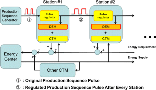
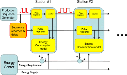
In this study, similar to other discrete event manufacturing simulations, the model is also driven by the production sequence signal that is used to imitate the production line. Figure illustrates the proposed simulation strategy within the plant control volume; i.e. energy center refers to the plant energy management center responsible for buying energy from the grid, and fossil fuel providers. However, unlike the Every Product Every framework that treat the time as an attribute of the sequence signal, in this proposed hybrid simulation, the sequence signal is accurately synchronized with the real-time frame. The main advantage here is the inherent flexibility in terms of time scale and its versatility in terms of its applicability to different stations. More importantly, this method enables the CTM events to work in parallel with the DEMs within the same simulation model. Though the real-time simulation still requires more computational resources, but selecting a reasonable step size and the right Central Processing Unit (CPU), can facilitate the management of memory requirements.
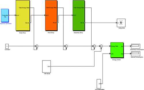
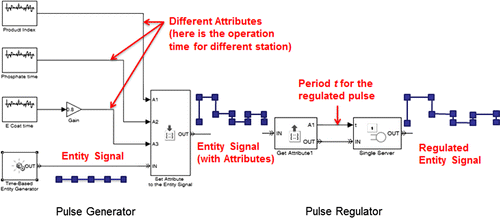
Figure displays the realization of the proposed simulation strategy in Matlab/Simulink®. The SimEvents® package has been employed to generate and regulate the sequence signal.
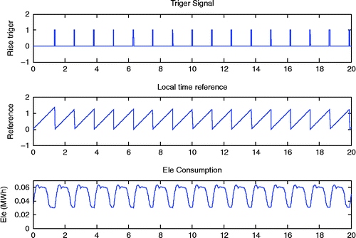
The period of the pulse signal as in Figure is synchronized with the real-time frame, with the amplitude showing one of the attribute information (e.g. running different vehicle models on the same line). The entity signal, which is used to represent the production sequence, is treated as a discrete event in SimEvent®. In order to capture the dynamics of every period in the sequence, the simulation should be able to apply the Energy Signature Models (ESMs) to reflect the energy consumption rate of a procedure or equipment during a specific period of the production sequence; this signature can be generated from that equipment or cell meter readings. Therefore, a local time reference is created to power the ESMs, selected to be a 45 degree ramp signal for current study, which is further triggered and reset by the entity signal; as depicted in Figure .
3.2 Statistical model and the hybrid simulation concept
The second fold of the proposed hybrid modelling approach is to employ regression analysis to generate energy trends and signatures for certain sections of the facility. Regression analysis is a well-accepted statistical method that is used to identify the causal relationships in production environments. The developed regression models for the current case study are based on readings from a network of meters and sensors that monitor the energy inputs, conversions (Land-Fill Gas (LFG) through Co-generation into hot water (HW), Electricity, and then the generated Electricity through centrifugal chillers into chilled water (CW), compressed air (CA)), and expenditures. The regression used models used in this study are developed based on data accumulated for the past 2 years of production.
The difficulty of applying the regression models within energy analysis for a manufacturing facility is due to the fact that the required independent variables will include the production volume of a certain period of time, typically much larger than the simulation step size. To provide an example, in the proposed model; the regression is done on daily basis while the simulation step size is set to one minute. In the automobile industry, the takt time, the maximum time to perform a single task/action, is about 55 s. As a result, using a step size of one minute allows capturing the important energy flows taking place within the manufacturing plant. So, in a simulation driven by the production sequence, the production volume will remain unknown until the simulation run is completed for that production period. So, this study proposes two methods to resolve this issue. The first is termed the daily volume prediction model, while the second is called the sequence record and delay model. Below sub-sections will describe each approach in more details.
3.2.1 Daily volume prediction model
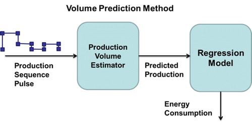
In this model, a specific production-volume prediction model is applied ahead of the regression model. Thus, the prediction model will read the sequence signal and calculate the production rate. Equipped with the information of the current production numbers and the remaining working hours, the model will make a prediction of the production-volume. This value will then be fed into the regression model to calculate the energy consumed for that production period in addition to the consumption rate for that moment; this is illustrated pictorially in the block-diagram in Figure .
3.2.2 Sequence record and delay model
In this method, the general simulation structure is altered such that the sequence signal runs through the same generation and regulation process without powering/triggering any energy consumption models. Then, a pulse counter calculates the production volume for that specific period. A sequence recorder then memorizes the sequence signal and delays that signal for the same period of time. The delayed sequence then triggers the second loop of the simulation, which will then output the energy consumption information. Figure displays the sequence record and delay model.
4. Running the simulation model for the case under study
Two modes are constructed for the automotive assembly facility under study. Both modes are designed to predict the energy consumption, including Electricity (from the grid), natural gas (NG) and LFG, for a full production day.
The factory has three main shops namely; the body shop, the paint shop, and a final assembly shop; it does not have a stamping press shop, consistent with most of the US-based automobile assembly factories. Thus, the factory receives stamped panels (around 500 panels per automobile) from another press facility or a subcontractor; through its different welding cells within the body-shop area; where the mechanical joining, robotic fusion and resistance based welding, in addition to adhesive bonding, are applied to create the body modules. Then, a sequential welding line joins the modules to create the body shell and the needed metallic reinforcements, thus, a complete Body-In-White (BIW) (un-painted vehicle shell) emerges from the bodyshop and moved into the paint-line. The paining-shop operates on the BIW through a series of treatment steps to clean the metal and condition its surfaces to receive different layers of paint. The painting process is based on dip and spray steps, where the BIW is submerged in the dip-tanks to receive a phosphate layer of paint; then the spray-based applicators coat the vehicle shell with a primer-film, a base-coat (with colour pigments and UV absorbers), and a clear-coat (for scratch resistance). The painting process is the most energy intensive within the assembly facility due to the air-conditioning requirements within the painting booths, in addition to the water recycling and filtering (separation of overspray paint from the scrubber's water) activities, and also the multiple curing ovens used for each layer of paint. In some plants more than 40% of the plant energy (process level) is consumed within the painting booths. The painted vehicle is then sent to the final assembly, to marry the shell with the power-train, and to add the electrical wiring, glass, etc. Other steps within the manufacturing cycle include; testing and re-work.
The facility under study has an energy management center to manage and monitor the input energy to the plant and to control its transformation. The plant runs a three-shift scheme; two shifts at 8 h and one shift at 4 h, and produces three different modalities of vehicles based on a similar Sport Utility Vehicle (SUV) platform, at a rate of 863 units/day. The plant host around 2500 workers spread amongst the different shifts and in different capacities; shoo floor and administrative offices. The plant has been fitted with variety of meters installed in different locations within the three shops to provide data for the regression modelling; such that the virtual shops are constructed via a daily regression model, to calculate the consumption of HW, CW, Electricity and NG. The simulation also employs a CTM model for the plant energy management center, which is responsible for buying the three energy inputs (Elec., NG, and LFG) and managing their transformations (LFG to Elec., and HW through Co-generation, etc.). So, dedicated conversion or transformation models are designed to constantly gather the energy requirement (energy type/quality and quantity) for each of the different shops, and then calculate the total consumption of Electricity, NG and LFG. The regression of the energy consumed within each station is set as a second order linear regression model based on three variables, i.e. number of Cooling Degree Days (CDD), number of Heating Degree Days (HDD) and the hourly production rate (units/h, or daily volume/working hours). The regression relationship is mathematically explained in Equation (1) with Table showing the R2 analysis of the fit.
Table 1 R2 analysis of the regression model.
Table shows that the prediction model and the time delay model results, indicating that both can generate predictions in agreement with the regression analysis. Although the time delay model provides more accuracy, it still requires more computational resources. Inspecting Table , specifically the R2 values indicate that the regression model of the HW requirements and electricity consumption are not ideal, still when inspecting Table , one should bear in mind that the regression applied is nonlinear regression hence the R2 low values. Additionally, the choice of the parameters in the regression displayed in Equation (1) is found more accurate in predicting the average plant consumptions; another choice of regression parameters can decompose the productivity Prod into: number of units and working hours instead. The latter choice can capture the dynamics of the consumption (time varying nature) but with lesser accuracy in terms of the values; this can be demonstrated by comparing the regression predictions vs. the actual plant data in Figure (a) and (b).
Table 2 Comparison between production prediction model, time delay model and regression analysis.
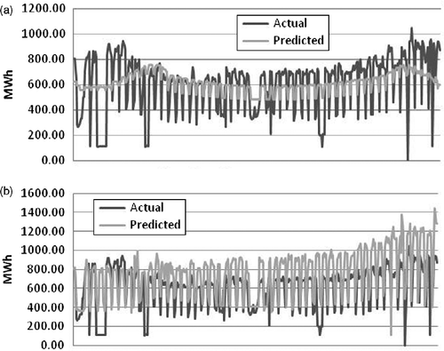
In order to improve this discrepancy, the simulation model can apply an ESM while replacing the corresponding section of that regression model. In this presented case study, the regression model of the electricity consumption for the body shop has been replaced by an ESM. As for the HW consumption, a thermo-dynamic (physical), Equation (2), model for the entire plant is constructed, and then integrated into the simulation to replace the HW regression model, hence, HW can be estimated.
In quasi-static analysis, the room temperature is stabilized with the thermal control system, which means and T2 = constant. Then the energy input rate becomes as in Equation (3).
A Graphical User Interface (GUI) is designed to improve the user-code interface. The GUI is capable of displaying the predicted daily consumption through the entire week and calculating the overall average energy consumption of each unit with some given parameters. This is designed to facilitate the energy/production planning activities on a weekly basis and can be easily extended to weekly or monthly basis because the simulation has regression models arranged for different time periods (weekly, monthly, etc.).
5. Discussions and conclusion
The presented manuscript illustrated a successful coupling between the DEM and the CTM models through the generation of the local time reference within the proposed hybrid simulation; Table has also shown that the predictions from proposed model are in agreement with the regression analysis done on actual data from the plant, which is based on comprehensive list of data loggers and meters that accumulated data for extended period of time (2 years). Additionally, this study discussed two different modes to facilitate the integration of the regression models within the simulation platform; namely the daily volume and the delayed mode. Also, current simulation work highlighted the flexibility of the proposed code in replacing the regression based sub-models with physical ones for certain processes or sections; such as the HW. At the same time, there is still a noticeable difference between the simulation predictions and the actual data, such deviation is believed to be due to the regression accuracy of other sub-models. By switching parts of the model (e.g. the electricity consumption of the body shop and the HW consumption) into an ESM or a dynamic model, the simulation accuracy can be further improved, as shown in this case study. Additionally, running the simulation on longer time periods (e.g. weekly or monthly basis) can further increase the simulation accuracy. The proposed simulation model has been further complemented with another regression model to address the non-working days (holidays, Sundays, etc.) situation because the hybrid simulation engine is designed to be triggered and controlled by the production sequence signal, which is not available at non-working days. The non-working days' contribution (in terms of energy consumption) should not be neglected; in some cases, it can account up to 40% of the total energy consumed. Future work include; embedding the presented simulation code into a feedback loop system along with an optimizer to propose different energy optimization schemes or strategies using different cost and penalty functions. Additionally, such optimization will be done at different dynamics; high and low refresh rates using a Model Predictive Control (MPC) and linear programming, respectively. The MPC will offer the ability to embed the whole simulation and optimization within a Knowledge Based System logic platform to offer an computerized-advisory processor capable of aiding energy planners and the Energy Management Center's engineers to better manage the input energy mix for current and future plants and under operating conditions. Additionally, future work will include further refinement to the regression model parameters selection to improve the overall accuracy of the predictions under low and high refresh rates. Also, the model can be complemented with an option to distinguish the plant energy quality in terms of renewable and non-renewable.
Disclosure statement
No potential conflict of interest was reported by the authors.
References
- AndreassiL., M. V.Ciminelli, M.Feola, and S.Ubertini. 2009. “Innovative Method for Energy Management: Modeling and Optimal Operation of Energy Systems.” International Journal of Energy and Building41 (4): 436–444. doi:10.1016/j.enbuild.2008.11.010.
- BalanR., S. D.Stan, and C.Lapusan. 2009. “A Model Based Predictive Control Algorithm for Building Temperature Control.” Paper presented at the 3rd IEEE International Conference on Digital Ecosystems and Technologies, Istanbul, May/June 31-03.
- BoydA. G.2005. Development of a Performance-Based Industrial Energy Efficiency Indicator for Automobile Assembly Plants. Chicago: Argonne National Laboratory.
- DevoldereT., W.Dewulf, W.Deprez, B.Willems, and R. J.Duflou. 2007. “Improvement Potentials for Energy Consumption in Discrete Part Production Machines.” Paper presented at the 14th CIRP Conference on Life Cycle Engineering, Tokyo, June 11–13.
- GalitskyC., and E.Worrell. 2003. Energy Efficiency Improvements and Cost Savings Opportunities for the Vehicle Assembly Industry: An ENERGY STAR® Guide for Energy and Plant Managers, Berkeley.
- GutowskiT., J.Dahmus, and A.Thiriez. 2006. “Electrical Energy Requirements for a Manufacturing Process.” Paper presented at the 13th CIRP International Conference on Life Cycle Engineering, Leuven, May/June 31–02.
- HeilalaJ., S.Vatanen, J.Montonen, H.Tonteri, B.Johansson, J.Stahre, and S.Lind. 2008. “Simulation-Based Sustainable Manufacturing System Design.” Paper presented at the 2008 Winter Simulation Conference, Austin, December 7–10.
- HerrmannC., and S.Thiede. 2009. “Process Chain Simulation to Foster Energy Efficiency in Manufacturing.” CIRP Journal of Manufacturing Science and Technology1 (4): 221–229. doi:10.1016/j.cirpj.2009.06.005.
- HerrmannC., S.Thiede, S.Kara, and J.Hesselbach. 2011. “Energy Oriented Simulation of Manufacturing Systems-Concept and Application.” CIRP Annals – Manufacturing Technology60 (1): 45–48. doi:10.1016/j.cirp.2011.03.127.
- HesselbachJ., C.Herrmann, R.Detzer, L.Martin, S.Thiede, and B.Lüdemann. 2008. “Energy Efficiency through Optimized Coordination of Production and Technical Building Services.” Presented at the 15th CIRP International Conference on Life Cycle Engineering, Sydney, March 17–18.
- JohanssonB., R.Kacker, R.Kessel, C.McLean, and R.Sriram. 2009. “Utilizing Combinatorial Testing on Discrete Event Simulation Models for Sustainable Manufacturing.” Paper presented at the 29th Computers and Information in Engineering Conference, San Diego, August/September 30–02.
- LauH. C. W., E. N. M.Cheng, C. K. M.Lee, and G. T. SHo. 2008. “A Fuzzy Logic Approach to Forecast Energy Consumption Change in a Manufacturing System.” Expert Systems with Application34 (3): 1813–1824. doi:10.1016/j.eswa.2007.02.015.
- LindS., B.Krassi, B.Johansson, J.Viitaniemi, J.Heilala, J.Stahre, S.Vatanen, A.Fasth, and C.Berlin. 2008. “SIMTER: A Production Simulation Tool for Joint Assessment of Ergonomics, Level of Automation and Environmental Impacts.” Paper presented at the 18th International Conference on Flexible Automation and Intelligent Manufacturing, Skövde, June/July 30–02.
- LindS., B.Krassi, J.Viitaniemi, S.Kiviranta, J.Heilala, and C.Berlin. 2008. “Linking Ergonomics Simulation to Production Process Development.” Paper presented at the 40th Conference on Winter Simulation, Miami, December 07–10.
- MillsE., G.Shamshoian, M.Blazek, P.Naughton, R. S.Seese, W.Tschudi, and D.Sartor. 2008. “The Business Case for Energy Management in High-tech Industries.” Energy Efficiency Journal1 (1): 5–20. doi:10.1007/s12053-007-9000-8.
- OmarA.2011. Automotive Manufacturing Processes and Systems. London: John Wiley.
- PatilY., J.Seryak, and K.Kissock. 2003. “Benchmarking Approaches: an Alternate Method to Determine Best Practice by Examining Plant-Wide Energy Signatures.” Paper presented at the ACEEE Summer Study on Energy-Efficiency in Industry, New York, July 19–22.
- RahimifardS., Y.Seow, and T.Childs. 2010. “Minimizing Embodied Product Energy to Support Energy Efficient Manufacturing.” CIRP Annals – Manufacturing Techmology59 (1): 25–28. doi:10.1016/j.cirp.2010.03.048.
- SeowY., S.Rahimifard, and E.Woolley. 2013. “Simulation of Energy Consumption in the Manufacture of a Product.” International Journal of Computer Integrated Manufacturing26 (7): 663–680. doi:10.1080/0951192X.2012.749533.
- U.S. DOE (U.S. Department of Energy). 2011. “Report on the First Quadrennial Technology Review.”
- WohlgemuthV., B.Page, and W.Kreutzer. 2006. “Combining Discrete Event Simulation and Material Flow Analysis in a Component-based Approach to Industrial Environmental Protection.” Environmental Modelling & Software21 (11): 1607–1617. doi:10.1016/j.envsoft.2006.05.015.

