Abstract
With the increasing penetration of doubly fed induction generators (DFIGs), the impact of the DFIG on transient stability attracts great attention. Transient stability is largely dominated by generator types in the power system, and the dynamic characteristics of DFIG wind turbines are different from that of the synchronous generators in the conventional power plants. The analysis of the transient stability on DFIG integrated power systems has become a very important issue. This paper reviews the current research on the issue from two aspects. One is to describe the methods to improve the fault ride through capability of DFIG wind turbines and the other is to analyse the impact of the DFIG wind farm on transient stability of power systems.
| Abbreviations | ||
| DFIG | = | doubly fed induction generators |
| VFC | = | variable frequency AC/DC/AC converter |
| FRT | = | fault ride through |
| RSC | = | rotor side converter |
| GSC | = | grid side converter |
| CCT | = | critical clearing time |
| TRASI | = | transient rotor angle stability index |
| TSI | = | transient stability index |
| SVC | = | static volt–ampere reactive compensator |
| STATCOM | = | static synchronous compensator |
| PWM | = | pulse width modulator |
| TEF | = | transient energy function |
1. Introduction
Due to high depletion of conventional energy sources and increasing environmental concern, more effort is put in electricity generation from renewable energy sources. Among various renewable energy sources, wind power is the most rapidly growing one due to its renewable, resourceful and pollution-free characteristics.
Wind energy conversion system commonly employs the squirrel cage induction generator, a fixed-speed wind energy generation system, which has a number of drawbacks (Morren and de Haan Citation2005). However, most of the drawbacks can be overcome by using variable speed wind turbines. With the recent progress in power electronics, wind turbines equipped with doubly fed induction generator (DFIG) have drawn increasing attention.
The DFIG comprises a wound rotor induction generator that is grid-connected at the stator terminals as well as at the rotor mains via a partially rated variable frequency AC/DC/AC converter (VFC). The VFC consists of a rotor side converter (RSC) and a grid side converter (GSC) connected back-to-back by a DC-link capacitor. The VFC takes a full control of the generator, such as decoupled control of active and reactive power, faster dynamic response with low harmonic distortion and handling only a very small fraction (25–30%) of the total power (Nunes et al. Citation2004). The DFIG wind turbine also improves system efficiency with its optimal rotational speed, it reduces noise and mechanical stresses, it improves power quality and it compensates for torque and power pulsations (Morren and de Haan Citation2005).
Higher installation capacity of the DFIG wind farm brings about wider influence of wind power on the grid and causes a major change in the operating conditions of the power systems during transient events (Hossain et al. Citation2012a). This is due to the fact that transient stability is largely dominated by generator technologies in the power system and dynamic characteristics of DFIG wind turbines are different from that of the synchronous generators (SGs) in the conventional power plants.
During faults, DFIG wind turbines are usually required to be disconnected from the grid to prevent machines from any adverse impact following the fault. Prior to disconnection, the DFIG wind turbines cannot support the voltage and the frequency of the grid during and immediately after the grid fault like the conventional synchronous generator power plants. With larger wind energy integration in the grid, DFIG wind turbines are having more influence on the overall transient stability and are required to sustain the fault ride through (FRT) operation (which means remaining connected to the grid following a fault), otherwise this would cause major problems for the system stability (Slootweg and Kling Citation2002). The FRT capability of wind turbines is a very important grid code requirement in the countries with high level of wind power penetration (Eltra Citation2000; Erlich and Bachmann Citation2005).
This paper mainly reviews previous literatures on two important aspects of transient stability of DFIG integrated power systems. One is to describe the methods to improve the FRT capability of DFIG wind turbines and the other is to analyse the impact of the DFIG wind farm on transient stability of power systems. This paper is organized as follows. The system configuration of DFIG wind turbine is briefly presented in Section 2. The methods of transient stability assessment are stated in Section 3. Transient phenomena and the methods of FRT operation with DFIG wind turbine are detailed in Sections 4 and 5, respectively. A brief description on the impact of DFIG wind farm on transient stability of power systems with future research option is presented in Section 6. Finally, the conclusions are drawn in Section 7.
2. System configuration of DFIG wind turbine
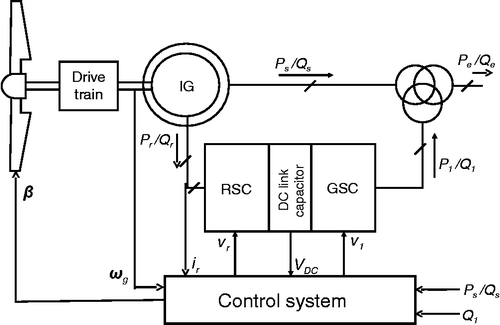
This section gives a brief description of dynamic mathematical modelling of DFIG wind turbine. It can be modelled in terms of behaviour equations of each of the subsystems, mainly the turbine, the drive train, the induction generator and the control system. Detailed descriptions can be found in Chowdhury et al. (Citation2013a, Citation2013b), Ekanayake et al. (Citation2003), Fernández, Jurado, and Saenz (Citation2008), García-Gracia et al. (Citation2008), Ghennam, Berkouk, and Francois (Citation2009), Gomis-Bellmunt et al. (Citation2008), Lima et al. (Citation2010), Pak and Dinavahi (Citation2009), Morren and de Haan (Citation2005), Slootweg et al. (Citation2003), Tapia et al. (Citation2003), Qiao, Venayagamoorthy, and Harley (Citation2009). The configuration of a DFIG wind turbine is shown in Figure .
2.1 Wind turbine model
Cp–λ–β curve gives the characteristics of the aerodynamic model of a wind turbine. The mechanical torque (Tm) extracted from the wind by the wind turbine can be expressed as
Cp is approximated by
2.2 Drive train model
The rotor is conventionally treated as two lumped masses, i.e. turbine mass and generator mass are connected together by a shaft with a certain damping and stiffness coefficient values. The mathematical equations of a two mass drive train model obtained by neglecting Dt and Dg are given as (Perdana Citation2008)
2.3 Generator model
A synchronously rotating d–q reference frame is chosen for generator modelling and Park equations determine the values of d and q axes voltage value of stator and rotor:
The electromagnetic torque is expressed as
The active and reactive powers (Pe and Qe) delivered to the grid are calculated as
2.4 Control system model
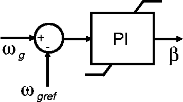
The control system is composed of three proportional-integral (PI) controllers, namely the RSC controller, the GSC controller and the pitch angle controller. The converter controllers generate the voltage command signal vr and v1 for the RSC and the GSC, respectively, in order to achieve decoupled control of active and reactive power, constant DC-linked capacitor voltage and grid terminal voltage. The pitch angle controller generates pitch angle command signal (β) for temporary reduction of wind turbine mechanical power by reducing Cp, when the rotor speed is over the value that sustains transient stability of power systems. Their detail explanation can be found in Salman and Badrzadeh (Citation2004).
Section 3 briefly discusses about different methods of transient stability assessment before describing the transient behaviour of the DFIG wind turbine.
3. Transient stability assessment
Transient stability is the capability of a power system to return to a stable operating point after the occurrence of a disturbance that changes its topology (Slootweg and Kling Citation2002). Examples of the topology change are as follows:
tripping of a generator or a line;
sudden change of a load, including a load trip;
occurrence of a fault, i.e. a short circuit.
Transient stability assessment of the power systems integrated with the DFIG turbines has been mainly reported in the following two aspects in the literature: (1) qualitative assessment and (2) quantitative assessment.
3.1 Qualitative assessment
Qualitative assessment is carried out by observing post-fault state of different generator parameters. The parameters are as follows:
Rotor angle: When the rotor angle of the generator drops out of phase, the generators are likely to lose the synchronism, leading to transiently unstable.
Rotor speed/active power: When the rotor speed/active power continuously increases without limitation or experiences fast undamped oscillations after the fault, the system is referred to as transiently unstable.
Terminal voltage: Quicker restoration of generator terminal voltage after the fault gives a good confidence on the system being stable.
Reactive power: When there is a heavy reactive power demand on the grid followed by the fault, the system may suffer from transient instability. This may be due to a voltage collapse of the network from the reduction of the reserves of the reactive power.
3.2 Quantitative assessment
Quantitative assessment is carried out by the following transient state measurement units:
Critical clearing time (CCT): The CCT is the maximal fault duration for which the system remains transiently stable. The CCT is a complex function of pre-fault system conditions (operating point, topology, system parameters), fault structure (type and location) and post-fault conditions that depend on the protective relaying plan employed. The CCT is conventionally calculated from equal area criterion theory (Kundur Citation1994). Another method computes the CCT though the computation of a trajectory on the stability boundary (Priyadi et al. Citation2012; Yorino et al. Citation2010).
Transient rotor angle stability index (TRASI): The TRASI is a comparative measure of rotor angle separation following a transient fault and defined as follows (Meegahapola and Flynn Citation2010):
The TRASI varies from 0 to 1. With the TRASI value closer to 1, the system is considered to be more stable.
Transient stability index (TSI): The TSI (η) is defined as follows (Gautam, Vittal, and Harbour Citation2009; Libao et al. Citation2009):
The TSI varies from − 100 to +100. With η value >0, the system is considered to be stable.
These qualitative and quantitative methods for transient stability assessment can be applied to evaluate transient response of the DFIG wind turbine.
4. Transient phenomena with DFIG wind turbines
This section gives a brief highlight of the transient phenomena of the power systems integrated with DFIG wind turbines. Detailed descriptions can be found in Ekanayake et al. (Citation2003), Perdana, Carlson, and Persson (Citation2004) and Sun, Chen, and Blaabjerg (Citation2005).
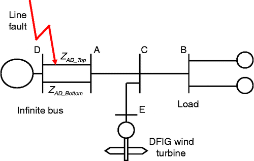
To assess the transient phenomena with a DFIG wind turbine, the simplest and most widely used test system is adopted from Badrzadeh and Salman (Citation2005), Ekanayake et al. (Citation2003), Holdsworth et al. (Citation2003) and Muljadi et al. (Citation2007) (Figure ). The DFIG wind turbine is added to the original network at Bus E and a short circuit fault is simulated on one of the lines between Buses A and D, which is cleared after nine cycles (0.15 s).
The Thevenin equivalent circuit, seen from Bus B, is shown in Figure . This is generally called the driving point impedance at Bus B found from the ZBus matrix of the power system network. With reference to the simplified diagram, the Thevenin impedance before the fault is
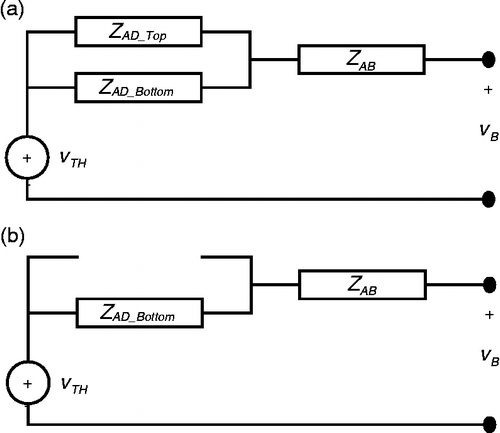
The Thevenin impedance after the fault is cleared is
It is clear that ZTh_PreF is less than ZTh_PostF, which weakens the system after fault.
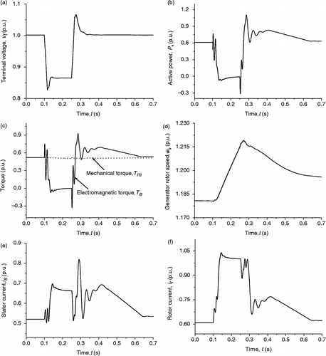
Perdana, Carlson, and Persson have carried out simulation to assess fault behaviour of a DFIG wind turbine. It is observed that the weaker system results in a large voltage drop across the generator terminal (vt) immediately after the fault initiated at 0.1 s (Figure (a)). The terminal voltage drop leads to corresponding generator rotor and stator flux decrease resulting in generator demagnetizing process. The active power (Pe) as well as the electromagnetic torque (Te) of the generator is consequently reduced (Figure (b)). Mechanical torque (Tm) gets higher as compared with the electromagnetic torque at a point (Figure (c)) and the generator rotor speed (ωg) starts accelerating (Figure (d)). High current transients (is and ir) appear in the stator and rotor windings (Figure (e),(f)). To prevent the converters from these high currents, the crowbar is triggered, the RSC is blocked and the GSC has a limited capability to transfer the whole power from the rotor through the converter further to the grid. As a result, the additional energy goes into charging the DC bus capacitor rapidly.
The shaft system between the wind turbine and the DFIG is extremely flexible, which causes to accumulate potential energy during normal operation. When a fault occurs, the energy is released and it causes the rotating mass of the shaft to excite oscillations (Akhmatov and Knudsen Citation2002).
When the fault is cleared at 0.25 s, the voltage cannot recover immediately because the blocked RSC cannot provide necessary reactive power to the generator for its magnetization process. The generator thus needs to absorb reactive power from the grid and this action delays the recovering process of the grid voltage and frequency. The GSC successfully controls the DC voltage back to its nominal value. When the grid voltage recovers over a certain value, the crowbar is removed. From the moment the voltage recovers completely, the generator currents and voltages start to converge to their pre-fault values and the RSC retains its control over the active and reactive power.
Section 5 describes the methods of enabling FRT operation of DFIG wind turbine.
5. FRT operation
The technology of the FRT capability of DFIG wind turbines has been significantly advanced for last few years. A number of methods have been adopted to sustain the FRT capability so that the transient stability is retained within a few seconds after fault clearance. These are as follows:
limiting rotor overcurrent;
shedding aerodynamic power;
damping torsional oscillations;
compensating reactive power.
5.1 Limiting rotor overcurrent
Limitation of rotor overcurrent for FRT capability has been achieved in a number of ways:
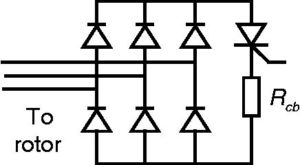
A protection device, namely ‘Crowbar’ is used to save the rotor circuit and power electronic converter from high rotor transient current (Pannell, Atkinson, and Zahawi Citation2010). The crowbar is an external rotor impedance, coupled via the slip rings to the generator rotor instead of the converter. The crowbar can be constructed by using a combination of a diode bridge and a thyristor with an external resistor (Figure ).
The crowbar resistance value typically ranges between 1 and 10 times the rotor resistance (Akhmatov Citation2002); however, the dimension is actually dependent on machine parameters. A higher crowbar resistance value is favourable to quickly dampen rotor transient current, but after a threshold it may lead to the risk of overvoltage on the converter. Therefore, the value of the resistance must be designed as a compromise between these two factors. The maximum value for the crowbar resistance (Rcb max) is estimated by Morren and de Haan (Citation2007):
where vr max is the maximum allowable rotor voltage,(19)
is the stator transient reactance and vs is the stator voltage vector.
The crowbar installation in the system has a number of limitations. It increases the cost and hinders its reliability. Moreover, the triggering of a crowbar causes the RSC blocking, which results in the operation of the generator as a squirrel-cage induction generator (SCIG). This often forces the disconnection of wind turbine generator (WTG), which is a complete violation of grid code requirement.
A flux weakening controller is used to weaken the undesired negative and zero sequence components in the stator flux linkage to keep the rotor current (Ir) to an acceptable limit (Figure ). Whether this is achievable depends on how strongly the voltage can be applied as compared with induced internal electromotive force (EMF). The stator flux linkage can be decomposed by a proper algorithm stated in Xiang et al. (Citation2006). An appropriate sharing of converter current capability is required to ensure individual cancellation of the negative and zero sequence components.
An arrangement is made to feedback the measured stator currents (Is) as the set point for the current controller of the RSC (
) when a fault causes voltage sag. In this manner, the current control system synthesizes rotor currents that generate current waveforms in the stator windings with the same shape of the currents generated during the sag but in counter phase to limit the stator overcurrent that consequently limits the rotor overcurrent.
As it is depicted in Figure , the control system under steady-state conditions would track the stator PQ references. The value of the stator current is then given by (Lima et al. Citation2010)
But, when the switch is triggered due to voltage sag, the external PQ control loop gets disconnected and the rotor currents set point matches the measured values of the stator currents in the dq reference frame, as indicated in the following equation:
Consequently, the stator current gets reduced due to more voltage drop in the current path.
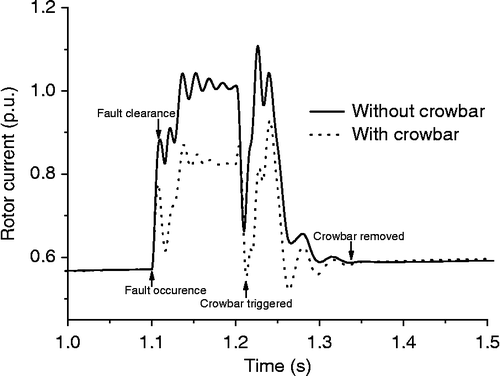
Pannell, Atkinson, and Zahawi have carried out the simulation to evaluate the effectiveness of the crowbar. In Figure , it is observed that the rotor current starts increasing until the overcurrent protection triggers the crowbar and inhibits the RSC in the moment of the fault.
5.2 Shedding aerodynamic power
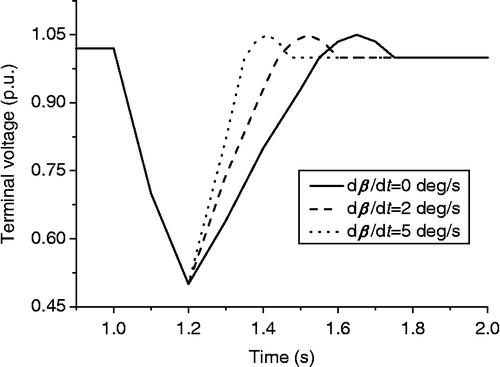
At a short circuit fault, the grid voltage and then the electromagnetic torque are significantly reduced, which leads to wind turbine acceleration. Aerodynamic power can be shed by generating pitch angle from any arbitrary operational point to below 20% of the rated power in < 2 s using the pitch angle controller to prevent the rotor from over speeding (Sun, Chen, and Blaabjerg Citation2005). Thus, the method boosts the FRT capability by quicker reestablishment of the generator terminal voltage (Holdsworth et al. Citation2004; Jauch et al. Citation2007), but is only effective up to a certain degree of fault in enabling the FRT operation.
The pitch angle controller is a simple PI controller that produces pitch angle (β) based on the deviation of generator rotor speed from its reference (as shown in Figure ). The reference value is taken as the minimum generator rotor speed, which enables the generation of maximum possible power from the WTG. This is determined from power tracking characteristics of the corresponding WTG.
Sun, Chen, and Blaabjerg have carried out the simulation to evaluate the effectiveness of the pitch angle controller. In Figure , it is observed that the terminal voltage takes the highest time to restore to its pre-fault value without any pitch angle controller. It is also seen that, the faster pitch rate of change (dβ/dt) helps restoring the terminal voltage more efficiently by reducing aerodynamic power faster.
5.3 Damping torsional oscillation
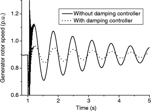
Oscillation, which is excited to rotating mass of the drive train followed by a grid fault, may prolong system stability. The torsional oscillations can be damped using the damping controller to enable the FRT operation of DFIG wind turbines (Mendes et al. Citation2011; Hansen and Michalke Citation2007). It is a simple PI controller that produces active power reference signal (Pref) for the RSC based on the deviation of generator rotor speed from its reference (as shown in Figure ). The speed reference is defined by the optimal speed curve at the incoming wind.
Hansen et al. have carried out the simulation to evaluate the effectiveness of the damping controller. In Figure , it is observed that the torsional oscillations excited by the grid fault are only slightly damped even after 5 s of the grid fault event without any damping controller, while the oscillations are quickly damped over few seconds when the damping controller is used. Furthermore, it indicates that the mechanical stress of the drive train is substantially reduced by employing damping controller.
The damping controller needs proper tuning. Insufficient tuning may lead to self-excitation of the drive train system and the risk of unnecessary tripping as protection against vibration in the mechanical construction (Hansen and Michalke Citation2007).
5.4 Compensating reactive power
During voltage recovery process following a transient fault, the GSC cannot provide necessary reactive power due to having converter with small capacity. As a result, the generator absorbs reactive power from the grid, resulting in further voltage and frequency instability. Such instability problems can be solved by compensating generator's reactive power demand dynamically to maintain the rapid regulation of the grid voltage (Hossain et al. Citation2012c), which is accomplished by two following methods:
After the RSC is blocked due to the triggering of the crowbar followed by a fault, it is reconfigured to be connected in parallel with the GSC by the static transfer switch. This arrangement ensures reactive current feeding from both converters to compensate the generator demand of reactive power. Reactive current may reach up to 1 p.u. through intensification by ‘Transient control mode’ (Kasem et al. Citation2008).
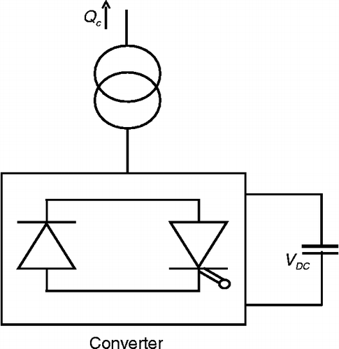
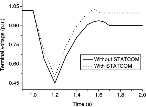
Shunt flexible AC transmission system devices, such as the static volt–ampere reactive compensator (SVC; Chompoo-inwai et al. Citation2005; Eping et al. Citation2005) and the static synchronous compensator (STATCOM; Hossain, Pota, and Ramos Citation2011, Citation2012b; Hossain et al. Citation2010; Qiao, Venayagamoorthy, and Harley Citation2009), are connected in shunt to the sending end bus. STATCOM is an advanced SVC consisting of a DC capacitor, a gate turn-off thyristor pulse width modulator (PWM) converter and a coupling transformer (Figure ). It generates a set of balanced three-phased sinusoidal voltages at the fundamental frequency with rapidly controllable amplitude and phase angle to drive PWM converter with DC-link capacitor and transport necessary reactive power (Qc) in the grid.
Hossain, Pota, and Ramos have carried out the simulation to evaluate the effectiveness of the STATCOM. In Figure , it is observed that the DFIG absorbs a large amount of reactive power as long as the RSC is blocked after the fault is cleared. The GSC cannot support the reactive compensation due to its small capacity. So, pre-fault value of the terminal voltage is not restored. The reactive compensation by the STATCOM enables the restoration of pre-fault value of the terminal voltage very efficiently.
The other research stream on transient stability of DFIG wind turbine is the impact of DFIG wind farm on transient stability, which is discussed in the following section.
6. Impact of DFIG wind farm on transient stability
Akhmatov (Citation2003) and Slootweg (Citation2003) pioneered to spot limelight on this research topic of impact of DFIG wind farm on transient stability of power systems. From their qualitative studies, it is known that the fault response of DFIG wind turbines for the largest part is determined by the settings of the protective system. Later, the impact of grid integration of wind power on transient stability in terms of generator types, power system topologies, fault types and location has been studied. It advocated that the transient stability would be enhanced if some traditional SGs are replaced with DFIGs of the same capacity (Li et al. Citation2009; Nunes et al. Citation2004). Further research reveals that the transient stability can be either improved or reduced when some traditional SGs are replaced with DFIGs of the same capacity (Samarasinghe and Ancell Citation2008). This finding is affirmed with the identification of electromechanical mode of oscillation using eigenvalue analysis that influences transient stability of power systems beneficially or detrimentally with increasing integration of DFIG turbines into power systems (Gautam, Vittal, and Harbour Citation2009). However, the qualitative study is unable to point to any definite transient status of power system. Rather, it can only provide a comparison of transient state between two different cases of transient events. Hence, no accurate and precise action can be taken from the limited qualitative study to significantly enhance the transient stability for the power system integrated with the DFIG wind farms.
The results obtained from the qualitative studies are verified quantitatively by means of the CCT (Yanhua et al. Citation2011), the TRASI (Meegahapola and Flynn Citation2010) and the TSI (Libao et al. Citation2009). A more extensive study has also been carried out that reveals the following:
Transient stability increases first and then decreases with the increasing capacity of DFIGs.
DFIG integration improves the system response to small disturbances, but it may have an adverse impact on the response to the larger ones.
A fault initiated close to DFIG wind farms results in more adverse effects on transient stability than a fault initiated near SGs.
6.1 Future quantitative research option
The results in the topic of the impact of the DFIG wind farm on transient stability in terms of fault location, fault type and wind power penetration level are limited to simplified network structures, a few fault scenarios, etc. The parameters used for the quantification of transient stability have limitations as well. The concept of the CCT is of limited value as far as a DFIG is concerned, because protection system is activated during fault negating transient stability assessment within the statutory limits (Badrzadeh and Salman Citation2005). The calculation of the post-fault rotor angle in the TRASI and the TSI can only measure the sensitivity of transient stability, i.e. the status of transient stability followed by a fault.
The authors have suggested carrying out the quantitative analysis through the assessment of exchange and conversion of transient energy by using transient energy function (TEF). Till date, the TEF has been applied in the conventional energy system (Fouad and Vittal Citation1992; Gautam, Vittal, and Harbour Citation2009; Kundur Citation1994) and may be modified for induction generator to enable transient stability assessment for power systems integrated with DFIG wind farms (Hosseinzadeh et al. Citation2014). This method would determine not only the status but also the degree of transient stability by yielding the information on the absorbing capability of the transient energy within the stability limit (if the post-disturbance system is stable) or the requirement of absorbing capability for switching into stable state (in case of the post-disturbance system being unstable; Chowdhury et al. Citation2015). Thus, the TEF may provide deeper insight into transient stability with a quicker decision, which makes it highly suitable to be implemented in the dynamic security assessment.
7. Conclusions
Higher installation capacity of the DFIG wind farm brings about wider influence of wind power on the grid and causes a major change in the operating conditions of the power systems during transient events. Transient stability is largely dominated by generator technologies in the power system, and dynamic characteristics of DFIG wind turbines are different from that of the SGs in the conventional power plants. Therefore, the analysis of transient stability of power systems integrated with the DFIGs has become a very important issue. This paper mainly assesses the current research stand on two important aspects of this issue. One is to describe methods to improve the FRT capability of DFIG wind turbines and the other is to analyse the impact of DFIG wind farm on transient stability of power systems.
Scientific assessment of transient stability is based on qualitative and quantitative methods. The quantitative method gives more precise measure on system's transient state than qualitative method. In general, the DFIG wind turbine suffers from high transient current, rotor overspeed, oscillations in the rotating mass of the shaft, grid voltage and frequency excursions subject to a transient fault. The efforts throughout the world result in inventing various methods such as limiting rotor overcurrent, shedding aerodynamic power, damping torsional oscillations and compensating reactive power. Our exploration is to make sustenance of FRT operation of DFIG wind turbines as a means of enhancing transient stability.
Extensive studies on the impact of DFIG wind farms on transient stability of power systems have been limited to simplified network structures and a few fault scenarios. Assessment of transient stability should be carried out quantitatively that can measure the sensitivity of transient stability, i.e. the status of transient stability followed by a fault. As a future research direction, the authors have suggested for quantitative analysis through the assessment of exchange and conversion of transient energy by using TEF that would determine not only the status but also the degree of transient stability of power systems.
Notes
References
- Akhmatov, V. 2002. “Variable-Speed WindTurbines with Doubly-Fed Induction Generators Part II: Power System Stability.” Wind Engineering 26 (3): 171–188. doi:10.1260/030952402762056081.
- Akhmatov, V. 2003. “Analysis of Dynamic Behavior of Electric Power Systems with Large Amount of Wind Power.” PhD diss., Technical University of Denmark.
- Akhmatov, V., and H. Knudsen. 2002. “An Aggregate Model of a Grid-Connected, Large-Scale, Offshore Wind Farm for Power Stability Investigations – Importance of Windmill Mechanical System.” International Journal of Electrical Power and Energy Systems 24 (9): 709–717. doi:10.1016/S0142-0615(01)00089-8.
- Badrzadeh, B., and S. K. Salman. 2005. “Critical Clearing Time of Doubly Fed Induction Generator.” Paper presented at the IEEE Power Tech Conference, Russia, June 27–30.
- Chompoo-inwai, C., C. Yingvivatanapong, K. Methaprayoon, and J. Lee. 2005. “Reactive Compensation Techniques to Improve the Ride-Through Capability of Wind Turbine During Disturbance.” IEEE Transactions on Industry Applications 41 (3): 666–672. doi:10.1109/TIA.2005.847283.
- Chowdhury, M. A., N. Hosseinzadeh, W. X. Shen, and H. R. Pota. 2013a. “Comparative Study on Fault Responses of Synchronous Generators and Wind Turbine Generators Using Transient Stability Index Based on Transient Energy Function.” International Journal of Electrical Power & Energy Systems 51 (0): 145–152. doi:10.1016/j.ijepes.2013.02.025.
- Chowdhury, M. A., W. X. Shen, N. Hosseinzadeh, and H. R. Pota. 2015. “Transient Stability of Power System Integrated with Doubly Fed Induction Generator Wind Farms.” IET Renewable Power Generation 9 (2): 184–194. doi:10.1049/iet-rpg.2014.0035.
- Chowdhury, M. A., W. X. Shen, N. Hosseinzadeh, and H. R. Pota. 2013b. “A Novel Aggregated DFIG Wind Farm Model Using Mechanical Torque Compensating Factor.” Energy Conversion and Management 67 (0): 265–274. doi:10.1016/j.enconman.2012.12.001.
- Chowdhury, M. A., W. X. Shen, N. Hosseinzadeh, and H. R. Pota. 2014. “Quantitative Assessment and Comparison of Fault Responses for Synchronous Generator and Wind Turbine Generators Based on Modified Transient Energy Function.” IET Renewable Power Generation 8 (5): 474–483. doi:10.1049/iet-rpg.2012.0323.
- Ekanayake, J. B., L. Holdsworth, W. Xueguang Wu, and N. Jenkins. 2003. “Dynamic Modeling of Doubly Fed Induction Generator Wind Turbines.” IEEE Transactions on Power Systems 18 (2): 803–809. doi:10.1109/TPWRS.2003.811178.
- Eltra. 2000. “Specifications for Connecting Wind Farms to the Transmission Network.” Eltra doc. no. 74174, April 26. Accessed 6 May, 2015. http://www.offshorecenter.dk/log/bibliotek/Specifications-Eltra.pdf.
- Eping, C., J. Stenzel, M. Poller, and H. Muller. 2005. “Impact of Large Scale Wind Power on Power System Stability.” Paper presented at the 5th International Workshop on Large-Scale Integration of Wind Power and Transmission Networks for Offshore Wind Farms, Glasgow, April 7–8.
- Erlich, I., and U. Bachmann. 2005. “Grid Code Requirements Concerning Connection and Operation of Wind Turbines in Germany.” Paper presented at the IEEE Power Engineering Society General Meeting, San Francisco, June 12–16.
- Fernández, L. M., F. Jurado, and J. R. Saenz. 2008. “Aggregated Dynamic Model for Wind Farms with Doubly Fed Induction Generator Wind Turbines.” Renewable Energy 33 (1): 129–140.
- Fouad, A. A., and V. Vittal. 1992. Power System Transient Stability Analysis Using the Transient Energy Function Method. Upper Saddle River, NJ: Prentice-Hall.
- García-Gracia, M., M. P. Comech, J. Sallán, and A. Llombart. 2008. “Modelling Wind Farms for Grid Disturbance Studies.” Renewable Energy 33 (9): 2109–2121.
- Gautam, D., V. Vittal, and T. Harbour. 2009. “Impact of Increased Penetration of DFIG-Based Wind Turbine Generators on Transient and Small Signal Stability of Power Systems.” IEEE Transactions on Power Systems 24 (3): 1426–1434. doi:10.1109/TPWRS.2009.2021234.
- Ghennam, T., E. M. Berkouk, and B. Francois. 2009. “Modeling and Control of a Doubly Fed Induction Generator (DFIG) Based Wind Conversion System.” Paper presented at the International Conference on Power Engineering, Energy and Electric Drives, Lisbon, March 18–20.
- Gomis-Bellmunt, O., A. Junyent-Ferré, A. Sumper, and J. Bergas-Jané. 2008. “Ride-Through Control of a Doubly Fed Induction Generator Under Unbalanced Voltage Sags.” IEEE Transactions on Energy Conversion 23 (4): 1036–1045. doi:10.1109/TEC.2008.2001440.
- Hansen, A. D., and G. Michalke. 2007. “Fault Ride-Through Capability of DFIG Wind Turbines.” Renewable Energy 32 (9): 1594–1610. doi:10.1016/j.renene.2006.10.008.
- Holdsworth, L., I. Charalambous, J. B. Ekanayake, and N. Jenkins. 2004. “Power System Fault Ride Through Capabilities of Induction Generator Based Wind Turbines.” Wind Engineering 28 (4): 399–409. doi:10.1260/0309524042886388.
- Holdsworth, L., X. G. Wu, J. B. Ekanayake, and N. Jenkins. 2003. “Comparison of Fixed Speed and Doubly-Fed Induction Wind Turbines During Power System Disturbances.” IEE Proceedings – Generation, Transmission and Distribution 150 (3): 343–352. doi:10.1049/ip-gtd:20030251.
- Hossain, M. J., H. R. Pota, M. A. Mahmud, and R. A. Ramos. 2012a. “Investigation of the Impacts of Large-Scale Wind Power Penetration on the Angle and Voltage Stability of Power Systems.” IEEE Systems Journal 6 (1): 76–84. doi:10.1109/JSYST.2011.2162991.
- Hossain, M. J., H. R. Pota, and R. A. Ramos. 2011. “Robust STATCOM Control for the Stabilisation of Fixed-Speed Wind Turbines During Low Voltages.” Renewable Energy 36 (11): 2897–2905. doi:10.1016/j.renene.2011.04.010.
- Hossain, M. J., H. R. Pota, and R. A. Ramos. 2012b. “Improved Low-Voltage-Ride-Through Capability of Fixedspeed Wind Turbines Using Decentralised Control of STATCOM with Energy Storage System.” IET Generation, Transmission & Distribution 6 (8): 719–730. doi:10.1049/iet-gtd.2011.0537.
- Hossain, M. J., H. R. Pota, V. A. Ugrinovskii, and R. A. Ramos. 2010. “Simultaneous STATCOM and Pitch Angle Control for Improved LVRT Capability of Fixed-Speed Wind Turbines.” IEEE Transactions on Sustainable Energy 1 (3): 142–151. doi:10.1109/TSTE.2010.2054118.
- Hossain, M. J., T. K. Saha, N. Mithulananthan, and H. R. Pota. 2012c. “Control Strategies for Augmenting LVRT Capability of DFIGs in Interconnected Power Systems.” IEEE Transactions on Industrial Electronics PP (99): 1–1.
- Jauch, C., S. M. Islam, P. Sørensen, and B. Bak Jensen. 2007. “Design of a Wind Turbine Pitch Angle Controller for Power System Stabilisation.” Renewable Energy 32 (14): 2334–2349. doi:10.1016/j.renene.2006.12.009.
- Kasem, A. H., E. F. El-Saadany, H. H. El-Tamaly, and M. A. A. Wahab. 2008. “An Improved Fault Ride-Through Strategy for Doubly Fed Induction Generator-Based Wind Turbines.” IET Renewable Power Generation 2 (4): 201–214. doi:10.1049/iet-rpg:20070092.
- Kundur, P. 1994. Power System Stability and Control. New York: McGraw-Hill.
- Li, L., H. Hongjing, L. Wenxia, and J. Sheng. 2009. “Simulation and Comparison of Transient Stability of Power System Including DFIGs Wind Farm Based on Detailed Model.” Paper presented at the International Conference on Sustainable Power Generation and Supply, Nanjing, April 6–7.
- Libao, S., D. Shiqiang, N. Yixin, Y. Liangzhong, and M. Bazargan. 2009. “Transient Stability of Power Systems with High Penetration of DFIG Based Wind Farms.” Paper presented at the IEEE Power & Energy Society General Meeting, Calgary, July 26–30.
- Lima, F. K. A., A. Luna, P. Rodriguez, E. H. Watanabe, and F. Blaabjerg. 2010. “Rotor Voltage Dynamics in the Doubly Fed Induction Generator During Grid Faults.” IEEE Transactions on Power Electronics 25 (1): 118–130. doi:10.1109/TPEL.2009.2025651.
- Meegahapola, L., and D. Flynn. 2010. “Impact on Transient and Frequency Stability for a Power System at Very High Wind Penetration.” Paper presented at the IEEE Power and Energy Society General Meeting, Minneapolis, July 25–29.
- Mendes, V. F., C. V. de Sousa, S. R. Silva, B. Rabelo Jr, and W. Hofmann. 2011. “Modeling and Ride-Through Control of Doubly Fed Induction Generators During Symmetrical Voltage Sags.” IEEE Transactions on Energy Conversion 26 (4): 1161–1171. doi:10.1109/TEC.2011.2163718.
- Morren, J., and S. W. H. de Haan. 2007. “Short-Circuit Current of Wind Turbines With Doubly Fed Induction Generator.” IEEE Transactions on Energy Conversion 22 (1): 174–180. doi:10.1109/TEC.2006.889615.
- Morren, J., and S. W. H. de Haan. 2005. “Ridethrough of Wind Turbines with Doubly-Fed Induction Generator During a Voltage Dip.” IEEE Transactions on Energy Conversion 20 (2): 435–441. doi:10.1109/TEC.2005.845526.
- Muljadi, E., C. P. Butterfield, B. Parsons, and A. Ellis. 2007. “Effect of Variable Speed Wind Turbine Generator on Stability of a Weak Grid.” IEEE Transactions on Energy Conversion 22 (1): 29–36. doi:10.1109/TEC.2006.889602.
- Nunes, M. V. A., J. A. P. Pecaslopes, H. H. Zurn, U. H. Bezerra, and R. G. Almeida. 2004. “Influence of the Variable-Speed Wind Generators in Transient Stability Margin of the Conventional Generators Integrated in Electrical Grids.” IEEE Transactions on Energy Conversion 19 (4): 692–701. doi:10.1109/TEC.2004.832078.
- Pak, L.-F., and V. Dinavahi. 2009. “Real-Time Simulation of a Wind Energy System Based on the Doubly-Fed Induction Generator.” IEEE Transactions on Power Systems 24 (3): 1301–1309. doi:10.1109/TPWRS.2009.2021200.
- Pannell, G., D. J. Atkinson, and B. Zahawi. 2010. “Minimum-Threshold Crowbar for a Fault-Ride-Through Grid-Code-Compliant DFIG Wind Turbine.” IEEE Transactions on Energy Conversion 25 (3): 750–759. doi:10.1109/TEC.2010.2046492.
- Perdana, A. 2008. “Dynamic Models of Wind Turbines.” PhD diss., Chalmers University of Technology.
- Perdana, A., O. Carlson, and J. Persson. 2004. “Dynamic Response of Grid-Connected Wind Turbine with Doubly Fed Induction Generator During Disturbances.” Paper presented at the Nordic Workshop on Power and Industrial Electronics, Trondheim, June 14–16.
- Priyadi, A., N. Yorino, M. Tanaka, T. Fujiwara, Y. Zoka, H. Kakui, and M. Takeshita. 2012. “A Direct Method for Obtaining Critical Clearing Time for Transient Stability Using Critical Generator Conditions.” European Transactions on Electrical Power 22 (5): 674–687. doi:10.1002/etep.597.
- Qiao, W., G. K. Venayagamoorthy, and R. G. Harley. 2009. “Real-Time Implementation of a STATCOM on a Wind Farm Equipped With Doubly Fed Induction Generators.” IEEE Transactions on Industry Applications 45 (1): 98–107. doi:10.1109/TIA.2008.2009377.
- Salman, S. K., and B. Badrzadeh. 2004. “New Approach for Modelling Doubly-Fed Induction Generator (DFIG) for Grid-Connection Studies.” Paper presented at the European wind energy conference and exhibition, London, November 22–25.
- Samarasinghe, C., and G. Ancell. 2008. “Effects of Large Scale Wind Generation on Transient Stability of the New Zealand Power System.” Paper presented at the IEEE Power and Energy Society General Meeting, Pittsburg, July 20–24.
- Slootweg, J. G. 2003. “Wind Power – Modelling and Impact on Power System Dynamics.” PhD diss., Delft University of Technology.
- Slootweg, J. G., S. W. H. de Haan, H. Polinder, and W. L. Kling. 2003. “General Model for Representing Variable Speed Wind Turbines in Power System Dynamics Simulations.” IEEE Transactions on Power Systems 18 (1): 144–151. doi:10.1109/TPWRS.2002.807113.
- Slootweg, J. G., and W. L. Kling. 2002. “Modelling and Analysing Impacts of Wind Power on Transient Stability of Power Systems.” Wind Engineering 26 (1): 3–20. doi:10.1260/030952402320775254.
- Sun, T., Z. Chen, and F. Blaabjerg. 2005. “Transient Stability of DFIG Wind Turbines at an External Short-Circuit Fault.” Wind Energy 8 (3): 345–360. doi:10.1002/we.164.
- Tapia, A., G. Tapia, J. X. Ostolaza, and J. R. Saenz. 2003. “Modeling and Control of a Wind Turbine Driven Doubly Fed Induction Generator.” IEEE Transactions on Energy Conversion 18 (2): 194–204. doi:10.1109/TEC.2003.811727.
- Xiang, D., R. Ran, P. J. Tavner, and S. Yang. 2006. “Control of a Doubly Fed Induction Generator in a Wind Turbine During Grid Fault Ride-Through.” IEEE Transactions on Energy Conversion 21 (3): 652–662. doi:10.1109/TEC.2006.875783.
- Yanhua, L., C. Yongning, W. Weisheng, and D. Huizhu. 2011. “Impacts of Large Scale Wind Power Integration on Power System.” Paper presented at the 4th International Conference on Electric Utility Deregulation and Restructuring and Power Technologies, Weihai, July 6–9.
- Yorino, N., A. Priyadi, H. Kakui, and M. Takeshita. 2010. “A New Method for Obtaining Critical Clearing Time for Transient Stability.” IEEE Transactions on Power Systems 25 (3): 1620–1626. doi:10.1109/TPWRS.2009.2040003.

