Abstract
A modified brushed permanent magnet DC (PMDC) motor has been developed and fabricated for a photovoltaic (PV)-operated solar systems. The conventional PMDC motor has been plagued with constraints, the most critical being ingestion of vapours of working fluid inside the rotor and stator, damaging the insulation of windings and forming a thin film of moisture between commutator and brushes. This flaw results into a very low mean time between failures of the motor. In the past, many attempts have been made where-in variety of seals to isolate the working fluid vapours from inner parts of motor have been tried out, but to no avail. Even Brushless DC motors have been designed in the past but their exorbitant cost makes the entire arrangement not viable economically. The modification attempted in this article overcomes the problem of working fluid ingestion inside the motor. It is found that mass flow rate of working fluid obtained at maximum peak sunshine hours is 17.5 l/min at 3030 rpm of motor driven by a PV module of 40 W at 16.20 V. This low-cost modified PMDC motor has been robust with high mean time between failures as no breakdown observed during 18 months of operation.
Nomenclature
| A | = | Number of parallel paths in rotor |
| Bm | = | Flux density in the air gap (Wb/m2) |
| Cw | = | Specific heat of water in solar still (J/kg-0K) |
| Eb | = | Back emf (V) |
| f | = | Frequency of magnet reversals (Hz) |
| K | = | Constant |
| Mw | = | Mass of water in tank (kg) |
| P | = | Number of poles |
| = | Rate of total useful energy transfer (W/m2) | |
| t | = | Thickness of each lamination (m) |
| Tw | = | Water temperature in tank (0C) |
| v | = | Volume of the core (m3) |
| Z | = | Total number of rotor conductors |
| η | = | Steinmetz hysteresis coefficient. |
| ∅ | = | Net emf (V) |
1 Introduction
Solar energy is a clean and healthy energy. It is therefore natural to tap this immense resource as it is not required to be explored, extracted, transported, mined, transmitted or imported. Solar thermal technology is employed for the purpose of collecting and converting the solar energy for applications such as water heating, air heating, cooking, drying, distillation, and irrigation (Singh, Kumar, and Tiwari Citation2011, Chow et al. Citation2010, Kumar and Tiwari Citation2009, Sutthivirode, Namprakai, and Roonprasang Citation2009, Glasnovic and Margeta Citation2007, Ji et al. Citation2007). The solar water heating is now a well-established technology. The use of solar water heaters can immensely help in the reduction of conventional energy produced from burning fossil fuels.
Generally the flat plate collectors are used for collecting the solar radiations required for water heating. The heated water is stored in an insulated storage tank. The transfer of the water/fluid from the collectors to the storage tank can be of two types – either natural (thermo-siphon) or forced circulation. However, for the water heating systems of large capacity or in case of irrigation the forced circulation mode has to be used.
A pump is used to circulate the fluid in forced mode. This pump can be rotated with the help of a motor that can be powered by the photovoltaic (PV) module. Therefore, the solar pump will have the three important ingredients – PV module, electric motor and a pump. Both AC and DC motors continue to offer unique benefits and features that may make one type or other better suited for certain applications.
AC drives use conventional, low cost, 3-phase AC induction motors for most applications. AC motors require virtually no maintenance and are preferred for applications where the motor is mounted in an area not easily accessible for servicing or replacement. AC motors are smaller, lighter and more commonly available, than DC motors. These motors are better suited for high-speed operations (more than 2500 rpm) since there are no brushes, and commutation is not a problem.
On the other hand, DC motors are less complex, very simple in construction and normally less expensive for most horsepower ratings. DC motors have a long tradition of use as adjustable speed machines and a wide range of options have evolved for this purpose. With properly applied brush and commutator, the required maintenance becomes minimal. DC motors are capable of providing starting and accelerating torques in excess of 400% of rated.
For solar pump applications, a DC motor can directly be operated by PV module. However, in case of AC pumps, there will be an additional requirement of voltage inverter for converting DC to AC, thereby increasing the cost of installation.
For the purpose of improving the overall efficiency of the solar pumps, many types of PV-driven electric motors have been tried out in the past, viz. brushed DC motor (Akbaba, Qamber, and Kamal Citation1998; Zaki and Eskander Citation1996; Koner, Joshi, and Chopra Citation1992), AC induction motor (Bhat, Pittet, and Sonde Citation1987), switched reluctance motor (Metwally and Anis Citation1994), and brushless DC (BLDC) motor (Singh, Putta Swamy, and Singh Citation1998; Langridge, Lawrance, and Wichert Citation1996). Most commonly, a conventional brushed permanent magnet DC (PMDC) motor is used due to its simplicity of construction and low cost. However, such motors used for solar pumps suffered with the serious operational drawbacks such as ingress of working fluid inside the motor (in the rotor/stator) leaking through seal separating motor from the pump. This leakage results into insulation failure in windings and the formation of thin film of moisture between commutator and brushes resulting into the voltage drop and increased maintenance due to such reasons.
Although many changes in the material and shape of the sealing ring on the shaft connecting the motor and pump were tried out in the past, the ingress of vapours/fluid into the motor could not be prevented completely, as the conventional design of the solar pump had both motor and pumps placed together with no gap between them on the connecting shaft. A brushless DC motor was developed for use in solar pumps, Swan, Allen, and Allen (Citation2010) overcame the flaws of the earlier generation solar pumps. This design does not use any seal between motor and pump, but this design proves to be of extremely high cost, thereby considered to be non-viable option economically.
In this work, the brushed DC motor for use in solar pumps has been improvised through modifications in such a manner that it no more suffers with the above mentioned limitations.
2 Description of first- and second-generation solar pumps
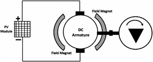
During 1980s the designed solar pumps were of first generation. The DC motor was having a set of brushes and it was directly connected to the input shaft of a pump as shown in Figure .
After using this pump, serious problem of leakage of working fluid into the motor was experienced (Appelbaum Citation1986). In the first-generation DC motor-driven solar pumps, powered by solar cells, the generated mechanical power is transmitted from motor to the pump via the connecting shaft. This entire rotating setup was operating with a dynamic seal that prevented the leakage of working fluid (Flitney Citation2007). This seal could not be made leak proof thereby unable to provide total elimination of leakage of fluid/vapours inside the motor. These motors also suffered with rise in temperature inside the casing due to poor ventilation as the casing.
Since their magnet field is active at all times even when motor is not being used, these motors are made totally enclosed to prevent their magnets from collecting magnetic junk from neighbourhood. Hence, as compared to wound-field motors, their temperature tends to be higher. However, it may not be of much of disadvantage in situations in which motor is used for short intervals. But in solar pump application, this motor needs to run during entire sunshine hours.
2.1 BLDC motor-driven solar pumps
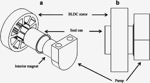
In the first-generation pumps, the issues were voltage mismatch and leakage. These issues were resolved by adding cost and increase in size of the components to the second-generation solar pumps. A simple step down DC to DC converter was added between the PV module and the motor terminals. The DC to DC converter transforms high voltage to low voltage and low current to high current at the input terminals of motor. As per Brennan (Citation1999), the dynamic seal has been replaced by a magnetic coupling.
An interior magnet is placed on the input shaft of the pump. Using static-o-ring interior magnet and pump, housing was sealed. The dynamic seal is no longer required. An exterior magnet is mounted to the motor shaft and positioned to surround the seal can, resulting in a magnetic, non-contact coupling that is capable of transmitting rotational mechanical power. Using this arrangement this static seal reduces the amount of leakage of working fluid. By taking the advantage of maximum power point (MPP) and magnetic coupling techniques evolved in second-generation pump, BLDC-based design has been developed, which reduces the volume and mass of the components hence reducing power consumption. Also by taking the advantage of advances in technology, BLDC stator with integrated control board was designed to replace the DC to DC converter. Using BLDC motor, the value of commutation becomes half, because BLDC motor uses the power electronics-based commutation rather than the mechanical commutation through brushes as in case of the Brushed DC Motor, Putta Swamy et al. (Citation2000).
Although, the use of static/dynamic seal got eliminated due to magnetic coupling in a BLDC motor; it had following drawbacks:
Due to the assembly of exterior magnet and interior magnet with the seal can, the power utilised is less and power wasted is of significant order. It involves an additional cost.
The control methodology used involves following three steps:
Need to first determine the rotor magnetic position to make the two phase separations.
Power supply control using FETs.
Requirement of power modulator to operate PV module near its MPP.
The air gap between exterior and interior magnets increases reluctance hence reduces overall rotor magnetic field flux thereby affecting adversely the conversion efficiency of this design.
The arrangement required the encapsulation of the magnet used to prevent corrosion by the circulating fluid. The gap and viscous loss is inherent to the magnetic coupling design. In this design the involved sensors also consume certain amount of power.
2.2 Modified first-generation PMDC motor
First-generation pumps of 1980 used a brushed DC motor that was directly connected to the input shaft of a pump. There was a significant drawback in this design. This drawback was due to the use of dynamic seal surrounding the input shaft that was prone to leakage of working fluid into the motor. The arrangement of motor and pump is shown in Figure .
In this article, certain modifications have been successfully attempted to overcome the drawback of fluid leakage inside the armature and commutator.
2.2.1 Modification of the permanent magnets arrangement in the stator
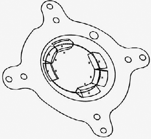
In the conventional DC motor, the arrangements of the permanent magnets of stator are appearing as shown in the Figure . In the modified DC motor, the stator is having three pairs of strong permanent magnets as shown in Figure .
These permanents magnets are going to create effectively two poles only, as in case of a conventional PMDC motor.
The advantage of this arrangement of magnets enhances the cross magnetisation. The small air gap between the consecutive magnets on either side of the stator will result in reduction of net magneto-motive force as shown in Figure (a) and (b).
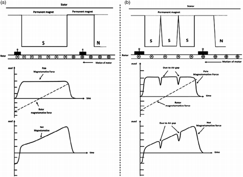
This small reduction in the net emf will result in an increase of rpm of the motor resulting into higher mass flow rate by the coupled pump.
The PMDC motor is similar to an ordinary DC shunt motor except that its field is provided by permanent magnets instead of salient pole wound-field structure. Accordingly, in PMDC motors, the torque is produced by interaction between the axial current-carrying rotor conductors and the magnetic flux produced by the permanent magnets. The speed of such a motor is given by Kothari and Nagrath (Citation2011), in the form of the standard relationship as:
The input voltage to the motor from PV module is almost constant during sunshine hours, that is around 16.5 V, resulting in negligible variation in Eb. Now, if the net emf ‘∅’ is reduced, it will increase the motor speed. It is to be noted here, however, that too much reduction in ∅ will adversely affect the torque.
As seen above, in DC motor, net flux weakening leads to increase of the motor speed. In this work, the modification in the permanent magnets of the stator has produced weaker net flux due to introduced air gap between consecutive magnets in either side resulting in higher speed.
3. Rotor shaft modification and carbon brush mounting mechanism
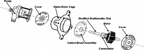
The modified rotor has an increased shaft length, transmitting the mechanical power from the motor to pump as shown in Figure (a). The rotor is of conventional design with 10 poles. The material of the rotor used is laminated cold rolled grain-oriented silicon steel. Poles of the rotor have shoe-shape tip. Commutator is mounted at conventional place. The brushes are mounted at regular place over the commutator and are internally assembled as shown in Figure (a) and Figure (b).
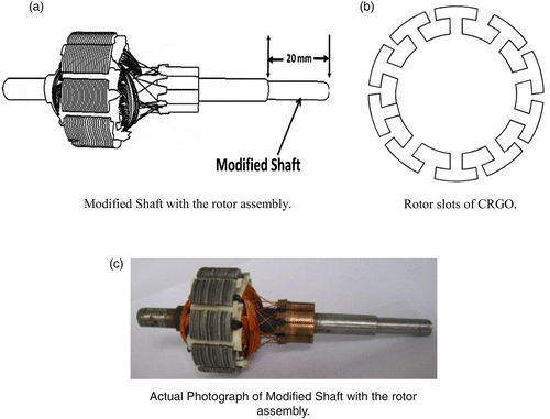
The effects of 2-pole stator to the 10-pole rotor gave the 3030 rpm and 17.5 l/min on a particular day (05 October 2012). The actual photograph of the rotor has been shown in Figure (c).
The shaft has been provided with a step as compared to conventional one. There is no direct contact of motor and the pump as they are located though on the same shaft but with a physical optimum space of approximately 20 mm. This arrangement completely eliminates the necessity of a seal as motor is separated from the working fluid inside the pump. This overcomes one of the major problems of working fluid leakage through dynamic/static seal into the motor.
The brush mounting mechanism has been shown in Figure (a) and (b).
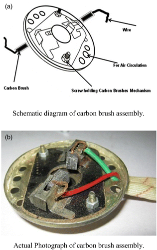
The carbon brush assemblies have been firmly housed with adequate spring tension to avoid any voltage drop.
3.1 Heat dissipation and air circulation mechanism for efficient cooling of motor
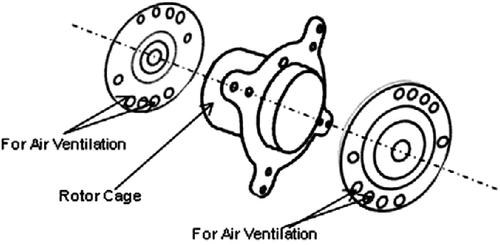
The arrangement for the ventilation of air is provided by introducing number of holes on the fore and aft circular cover plates of the motor as shown in Figure .
This scheme has proved itself satisfactory for the dissipation of heat generated inside the motor during its operation throughout the sunshine hours.
3.2 Complete assembly of improved PMDC motor
The various modified sub-assemblies have been put together and the schematic of the improvised PMDC motor is shown in Figure .
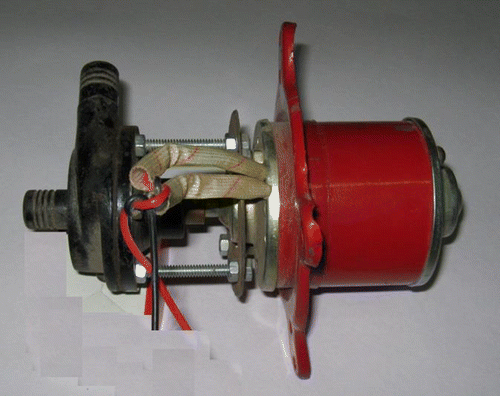
The actual photograph of the motor is shown in Figure .
4. Field trial
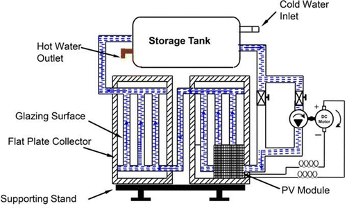
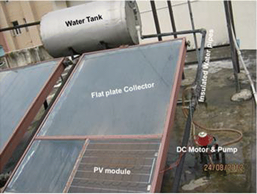
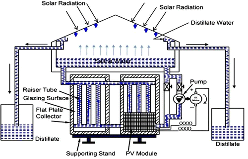
To test the modified PMDC motor and pump under field conditions, a hybrid photovoltaic thermal (PVT) water heating system was used. The photograph of fabricated hybrid PVT water heater is shown in Figure . The fabricated system consists of three components namely PV-integrated flat plate collectors, water storage tank and DC water pump. Two flat plate collectors are connected and integrated to the insulated storage tank of 200 l capacity using insulated pipes (insulated using thick rubber coating). The connection between the two flat plate collectors (series and parallel) could be changed in a controlled way by two check valves provided. The schematics of these two connections are shown in Figure .
Each collector has an effective area of 2.0 m2. The whole absorber is encased in an aluminum metallic box with 0.1 m glass wool insulation at base and side to reduce thermal losses. The toughened glasses of 0.004 m thick are fixed on the top of the boxes using aluminum frame and screws. The rubber seal is placed between the metallic box and glass cover as well as between glass and aluminum frame. A glass-to-glass PV module of 36 cells has been integrated at the bottom of one of the collector. The PV module has been manufactured by CEL, Ghaziabad, India and costs US$ 185.00. The flat plate collector has an effective area of 2.0 m2. The size of the integrated PV module is kept 0.55 m × 0.65 m (0.33 m2), which is approximately 17% of the area of flat plate of solar thermal unit (STU). The solar radiations pass through the non-packing area of the module as well as convected energy from back side of the module is utilised to heat the water flowing through the riser tubes below the module. The whole system is made vapour tight using silicone rubber sealant, as it remains elastic for long time. The unit is mounted on an iron stand oriented due south at an angle of 30°, which is nearly equal to a latitude of the place (i.e. 28o32′N, 77o12′E).
The DC motor-driven water pump is used to circulate the water in forced mode of operation. The cost of the pump is US$5.00. The pump is driven directly by the DC power generated by the PV module. The source of the water was the overhead tank that was used for providing the input to the first collector. In this system, the modified DC motor pump has been used to circulate the water in the forced mode. The actual photograph of the experimental set-up is shown in Figure .
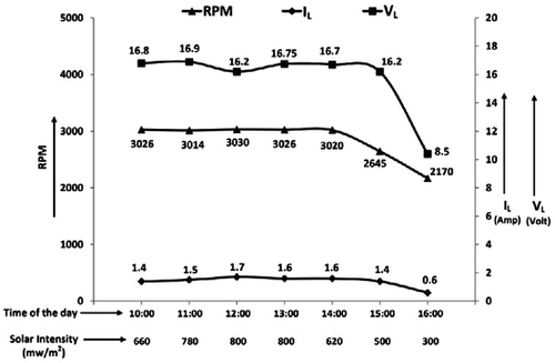
During the peak sunshine hours, the rpm of this motor was observed of the order 3030 rpm with a maximum fluid circulation of 17.5 l/min circulating capacity of water at 2 m head.
4.1 Voltage versus speed characteristics (at no-load)
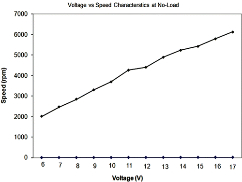
Voltage versus speed characteristics of the modified motor were obtained at no load. The characteristic shows that on increasing the voltage gradually, the speed of the modified motor varies linearly as seen in Figure .
It can be inferred that the speed of the motor is directly proportional to the applied voltage. In this curve, the rpm achieved at 17 V is 6133 rpm at no load. In modified DC motor, there are no field windings. The efficiency of such motor is higher as compared to the wound field DC motor as field windings cause certain losses.
4.2 Load voltage (vl) and Load Current (IL) vs RPM characteristics
During the day time from 10:00am to 4:00pm, the observations were recorded at various times on a particular day (05 October 2012). The load given to the motor was circulating water from a tank situated at the height of 2.0 m through the flat plate collectors. The solar intensity on hourly basis was also recorded.
The on-load performance characteristics of the motor obtained is shown in Figure .
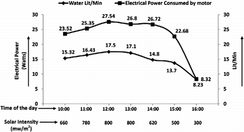
The flow rate of water by the PMDC motor-driven pump is shown in Figure . It is seen that on a particular day at 10:00 h, the flow rate is 15.32 l/min while it goes up to 17.5 l/min around 13:00 h. At 15:00 h, the flow rate obtained is 13.7 l/min. The mass flow rate during most of the sunshine hours of the day is adequate to maintain forced circulation of water.
4.3 Electrical power consumed versus mass flow rate characteristics of the modified motor at different solar intensity of the day
The water flow rate in litres per minute was recorded at different solar intensities during the sunshine hours. The characteristics so obtained have been shown in Figure .
It can be observed that the mass flow rate delivered by the motor is not only satisfactory but also does not have any significant variation during the sunshine hours. Due to good mass flow rate for present design of DC motor, no stratification has been observed inside the water storage tank resulting in providing water at constant temperature as delivery point.
4.4 Instantaneous efficiency of solar thermal with modified DC solar pump
The modified PMDC motor and pump was tried out on hybrid PVT solar water heater. The instantaneous efficiency of STU with new DC pump (in force circulation mode) was studied by Kumar et al. (Citation2013). The instantaneous efficiency for natural circulation mode has also been studied. It has been established that thermal efficiency in forced circulation mode is higher as compared to natural circulation mode. It is observed that thermal efficiency of the system with PVT- and PMDC-driven pumps in forced circulation mode is of the order of 50% as shown in Figure .
The solar energy inputs were almost similar, as the study was carried out on consecutive days on 4th, 5th and 6th October 2012.
4.5 Stored thermal energy of storage tank with modified DC solar pump
The stored energy in the tank in forced circulation mode has been presented by Kumar and Singh [22]. The thermal energy stored in the tank is given as:
4.6 Losses in PMDC motor
Losses in a PMDC motor are copper, iron and mechanical losses.
4.7 Copper losses
The copper losses are the losses taking place due to the current flowing in a winding. There is basically one windings in permanent magnet DC motor namely armature winding. The copper losses are proportional to the square of the current flowing through this winding (Vukosavic Citation2012).
4.8 Iron or core losses
These losses are also called magnetic losses. These losses include hysteresis loss and eddy current loss.
The hysteresis loss is proportional to the frequency and the maximum flux density Bm in the air gap and is given by Vukosavic (Citation2012),
4.9 Mechanical losses
These losses consist of friction and windage losses. Some power is required to overcome mechanical friction and wind resistance at the shaft. Mechanical losses are constant for a specific DC motor.
4.10 Life time and maintenance cost
The lifetime of BLDC, unmodified PMDC and modified PMDC motors are of same order.
The BLDC motor is almost maintenance free. On the other hand, the PMDC motor needs regular maintenance of carbon brushes. After certain usage, the brushes need even replacement. However, the advantage of using PMDC motor can be seen from the difference in the cost where-in the BLDC motor is almost 15–20 times costlier than PMDC motor of similar power. The issue of cost of maintenance of PMDC motor, therefore, becomes of no consequence.
4.11 Rain-proofing of motor
As the solar water heater systems are bound to be located in the open area, there may be need to provide rain-proofing to the DC motor so as to prevent any damage due to ingestion of water inside the motor. The modified PMDC motor can be made rainproof. It can be done with the help of appropriate covers with adequate ventilation for letting out the hot air/gases from inside the motor to escape to the environment.
5 Noise in the modified PMDC motor
5.1 Electrical source of noise
Brushes are major source of noise in a PMDC motor. The biggest noise spike from a DC motor occurs at the slot frequency of the motor. Brush noise can be decreased by finding a brush compound with a lower coefficient of friction and by optimizing the brush spring constant to decrease the amount of motion the brush makes perpendicular to the brush slot. However, electrical source of noise and vibration are not as significant as the mechanical system of the DC motors.
5.2 Mechanical sources of noise
The major part of noise from a permanent magnet DC motor is mainly from the vibration of the mechanical components. Shaft bearings can cause vibration and noise due to misalignment, improper lubrication and loose bearings. Use of low-noise bearings and lubricants helps in significant reduction in motor noise. Low-noise ball bearings have been used in the modified PMDC motor, resulting in smaller system oscillations and less instability that can lead to vibration and noise. Similarly, low-noise lubricants have more damping than standard lubricants. Fluoroester-based oil has been used, which dropped the noise level significantly.
5.3 Motor casing
Noise generated by brushes and commutator are also transmitted and amplified by the case and structure surrounding the motor. The modified motor has been designed in such a manner that helps in reduction in noise level inside the casing.
6 Result analysis
During the field usage of the modified PMDC motor, it has been established that it was totally free from any ingress of working fluid into the motor, which had been a serious problem in the past in these motors. The modified PMDC motor has been in field trial for 18 months with no failure of this nature. The field trial also revealed following advantages of the modified PMDC motor over the other motors for the use in solar pumps.
In small ratings, use of permanent-magnet excitation results in lowing the manufacturing cost. The cost of this modified motor of 40 Watt has been just US$30.00. The cost of BLDC motor is very high due to electronic commutator and magnetic coupling. Atypical BLDC motor, Maxon Motor, web page consulted the 12 of April (Citation2012) of 40 Watt, 24 V costs 24 V BLDC Motor of US$232, Motor EC-i 40, versus modified brushed PMDC motor of US$30.
The PMDC motor is simple in construction and operation whereas the motion controller and driver electronics needed to operate a BLDC motor are rare, more complex and expensive. Consequently, the selection of a BLDC motor is justified for specific applications but not considered a favourable option for solar pumps.
In PMDC motor, torque ripples (cogging torque) occur, which is caused by the tendency of the PM rotor to align itself into positions, facilitating smooth startup.
A PMDC motor is generally smaller in size than a wound-field DC motor of equal power rating. The modified motor for the use in solar pumps has been chosen accordingly as PMDC.
Since field excitation current is not required, the efficiency of these motors is generally higher than that of the wound-field motors as no winding losses in stator exist.
Low-voltage PMDC motors produce less air noise. When designed for low-voltage (as in case of PV module-operated motors), these motors produce very little radio and TV interference.
7.0 Conclusion
The problem posed by the static/dynamic seal in conventional PMDC motor was overcome in the BLDC motor as this modification removed the requirement of usage of conventional dynamic or static seal. In place of a circular seal, one may use a seal can to couple the motor and pump together. But the cost of such an arrangement becomes exorbitantly high as the cost of a 40 W BLDC motor is pegged at around US$232.00 (Maxon Motor, web page consulted the 12 of April Citation2012). The modified PMDC motor of 40 W as described in this article costs US$30.00. Therefore, the purpose and advantage of using a BLDC over a conventional DC motor got more or less defeated due to its high cost. The DC motor as described in this article with improvised features, that is, changes in the permanent magnets arrangement in the stator and changes in the rotating shaft has proved to be very successful. It also eliminated the use of dynamic or static seal, as in this case motor and pump were physically separated on the rotating shaft. This arrangement resulted in elimination of any possibility of ingress of moisture into the rotor windings and commutator segments, which was main cause for opting for a very expensive BLDC motor for solar pumps.
Disclosure statement
No potential conflict of interest was reported by the authors.
References
- Akbaba, Mehmet, Isa Qamber, and Adel Kamal. 1998. “Matching of Separately Excited Dc Motors to Photovoltaic Generators for Maximum Power Output.” Solar Energy 63 (6): 375–385. doi:10.1016/S0038-092X(98)00094-2.
- Appelbaum, J. 1986. “Performance Characteristics of a Permanent Magnet D.C. Motor Powered by Solar Cells.” Solar Cells 17 (2-3): 343–362. 10.1016/0379-6787(86)90022-0.
- Bhat, S. R., Andre Pittet, and B. S. Sonde. 1987. “Performance Optimization of Induction Motor-Pump System Using Photovoltaic Energy Source.” IEEE Transaction on Industrial Applications IA-23 (6): 995–1000. doi:10.1109/TIA.1987.4505020.
- Brennan, James R. 1999. “Applications for Magnetic Drive Rotary Positive Displacement Pumps.” World Pumps 1999 (390): 24–28. doi:10.1016/S0262-1762(00)87638-5.
- Chow, T. T., G. Pei, K. F. Fong, Z. Lin, A. L. S. Chan, and M. He. 2010. “Modeling and Application of Direct-Expansion Solar-Assisted Heat Pump for Water Heating in Subtropical Hong Kong.” Applied Energy 87 (2): 643–649. doi:10.1016/j.apenergy.2009.05.036.
- Flitney, Robert. 2007. “Seals and Sealing Handbook.” 10.1016/b978-185617461-9/50001-4.
- Glasnovic, Zvonimir, and Jure Margeta. 2007. “A Model for Optimal Sizing of Photovoltaic Irrigation Water Pumping Systems.” Solar Energy 81 (7): 904–916. doi:10.1016/j.solener.2006.11.003.
- Ji, Jie, Jian-Ping Lu, Tin-Tai Chow, Wei He, and Gang Pei. 2007. “A Sensitivity Study of a Hybrid Photovoltaic/thermal Water-Heating System with Natural Circulation.” Applied Energy 84 (2): 222–237. doi:10.1016/j.apenergy.2006.04.009.
- Koner, P. K., J. C. Joshi, and K. L. Chopra. 1992. “Matching Analysis of Photovoltaic Powered DC Series Motors and Centrifugal Pumps by Varing Motor Constants.” International Journal of Energy Research 16 (4): 301–313. doi:10.1002/er.4440160405.
- Kothari, D. P., and I. J. Nagrath. 2011. Electric Machines, DC Machines, 223-224. 4th ed. New Delhi. ISBN(13): 978-0-07-069967-0 Tata McGraw Hill.
- Kumar, Shiv, Gajendra Singh, G. N. Tiwari, and J. K. Yadav. 2013. “Thermal Modelling of a Hybrid Photovoltaic Thermal Water Heater in Parallel Configuration.” International Journal of Sustainable Energy 32 (5): 277–295. doi:10.1080/14786451.2011.644627.
- Kumar, Shiv, and G. N. Tiwari. 2009. “Life Cycle Cost Analysis of Single Slope Hybrid (PV/T) Active Solar Still.” Applied Energy 86 (10): 1995–2004. doi:10.1016/j.apenergy.2009.03.005.
- Langridge, D., W. Lawrance, and B. Wichert. 1996. “Development of a Photo-Voltaic Pumping System Using a Brushless D.C. Motor and Helical Rotor Pump.” Solar Energy 56 (2): 151–160. doi:10.1016/0038-092X(95)00077-5.
- Maxon Motor, web page consulted the 12 of April. Available from: http://www.maxonmotor.com/maxon/view/msp for the comparison of 24V BLDC Motor of USD $ 232, Motor EC-i 40, vs Modified Brushed PMDC Motor of USD $ 30. doi:10.1108/ir.2000.04927dad.002 2012.
- Metwally, Hamid M. B., and Wagdy R. Anis. 1994. “Performance Analysis of Photovoltaic-Powered Water-Pumping Systems Using Switched Reluctance Motor Drives.” Journal of Power Sources 52 (1): 141–147. doi:10.1016/0378-7753(94)01946-0.
- Putta Swamy, C. L., Bhim Singh, B. P. Singh, and S. S. Murthy. 2000. “Experimental Investigations on a Permanent Magnet Brushless DC Motor Fed by a PV Array for a Water Pumping System.” Journal of Solar Energy Engineering 122 (3): 129. doi:10.1115/1.1288596.
- Singh, Gajendra, Shiv Kumar, and G. N. Tiwari. 2011. “Design, Fabrication and Performance Evaluation of a Hybrid Photovoltaic Thermal (PVT) Double Slope Active Solar Still.” Desalination 277 (1–3): 399–406. doi:10.1016/j.desal.2011.04.064.
- Singh, Bhim, C. L. Putta Swamy, and B. P. Singh. 1998. “Analysis and Development of a Low-Cost Permanent Magnet Brushless DC Motor Drive for PV-Array Fed Water Pumping System.” Solar Energy Materials and Solar Cells 51 (1): 55–67. doi:10.1016/S0927-0248(97)00208-0.
- Sutthivirode, Kittiwoot, Pichai Namprakai, and Natthaphon Roonprasang. 2009. “A New Version of a Solar Water Heating System Coupled with a Solar Water Pump.” Applied Energy 86 (9): 1423–1430. doi:10.1016/j.apenergy.2008.12.002.
- Swan, G. Allen, and Peter L. Allen. 2010. “Integrated Solar Pump Design Incorporating a Brushless DC Motor for Use in a Solar Heating System.” Renewable Energy 35 (9): 2015–2026. doi:10.1016/j.renene.2010.02.002.
- Vukosavic, Slobodan N. 2012. “Introduction to DC Machines.” Electrical Machines: 259–298. doi:10.1007/978-1-4614-0400-2_11.
- Zaki, Aziza M., and Mona N. Eskander. 1996. “Matching of Photovolatic Motor-Pump Systems for Maximum Efficiency Operation.” Renewable Energy 7 (3): 279–288. doi:10.1016/0960-1481(95)00133-6.

