
Abstract
The paper explores the experimental results of the prototype compound parabolic trough made of mild steel and silver-coated selective surface. This prototype has been tested with top cover. The performance of the collector has been evaluated with two kinds of receivers coated with three types of black coatings. First receiver is of copper coated with black copper, second receiver is of mild steel coated with black copper and third receiver is of copper coated with black zinc. From actual field experiments, it has been observed that the efficiency of the system achieved with copper receiver coated with black copper is comparatively higher than the other two types of receivers. A simple regression analysis is used to correlate the thermal performance parameters of the system.
1. Introduction
Parabolic trough technology is commercially viable for utilizing solar heat as industrial process heat (IPH), especially in tropical countries where solar radiation is abundant. The demand for IPH is constant throughout the year and hence the capacity utilization of solar systems along with some hybrid systems for IPH can be very high. UNDP and Ministry of New and Renewable Energy, Government of India report, in several industries, number of processes, requires heat below 250 °C (Citation2013) which can easily and economically be supplied by solar devices. Thus, this low-temperature process heat requirement in industries makes the solar system quite attractive. The authors proposed a compound parabolic trough (CPT) system with top glass cover for possible application in industrial heating and low-pressure steam generation. The proposed system consists of a prototype CPT made of mild steel and its surface coated with a silver chrome-selective surface. Different researchers are working on concentrated solar power (CSP) for industrial heating. Several techniques have been proposed to evaluate the thermal performance of the compound parabolic collector (CPC) using thermal performance parameters. Brief literature has been cited in following section.
García et al (Citation2005) studied parabolic trough collectors. This paper also presents an overview of concentrating solar system which can provide heat energy up to 400 °C, for steam power cycles for electricity generation. A solar thermal system was proposed by Tsai and Lin (Citation2012) consisting of a variable focus parabolic trough solar collector and cylindrical heat-pipe receiver. The authors studied the path of solar rays within the collector system using a skew-ray tracing method and validated the performance of the proposed optimization method. The authors concluded that the optimized variable-focus parabolic trough-type concentrator shows a significant improvement in the irradiance uniformity and the heating efficiency compared to cylindrical parabolic trough (CPT) and parabolic trough concentrators (PTC). Huang, Hu, Chen (Citation2012) proposed a new optical performance model and a new algorithm which is used to simulate the performance of a solar parabolic trough collector and vacuum tube receiver. The authors also derived mathematical equations for optical efficiency and then the optical efficiency of the trough receiver system is simulated by new algorithm. Eck and Zarza (Citation2006) investigated future applications of saturated steam-operated DSG plants for power generation in small capacity. The authors concluded specific advantages of described system such as simple set-up of the collector field, safe collector field operation and higher thermal efficiency in the collector field. Kalogirou (Citation2012) experimented with conventional line focusing parabolic trough systems. Author explored a thermal model of a parabolic trough collector and the thermal analysis of the collector receiver. The model is validated with known performance of existing collectors. Thomas and Guven (Citation1993) explored review on the design aspects PTC. The authors also discussed different methods of performance evaluation and techniques to improve system performance. Gong et al (Citation2010) established and optimized one-dimensional theoretical model to compute the receiver’s major heat losses and factors responsible for heat loss. The heat losses of good vacuum and non-vacuum Sanle-3 receivers were surveyed by the authors under steady state. Authors comparison shows that the one-dimensional model agrees with the ends covered test while remarkably deviating from the end exposed test. Kamal Skeiker explains tilt angle with the horizon as an important factor for solar systems. Skeiker (Citation2009) developed a mathematical model for the solar collector in the Syrian zones, on a daily basis, as well as for a specific period for estimating the solar radiation on a tilted surface, and to determine the optimum tilt angle and the surface azimuth angle. Author concluded that optimization of tilt angle results in yearly gain of approximately 30% in solar radiation as compared to a solar collector fixed on a horizontal surface. Souliotis et al (Citation2011) developed a system based around a heat-retaining ICS vessel design which consist of two concentric cylindrical receivers mounted on line focus of a stationary truncated asymmetric CPT. The authors compared the thermal behaviour of the ICS system with flat plate thermosiphonic collector. Singh and Eames (Citation2012) experimentally studied the natural convective heat transfer in CPC cavities. The authors reported results for CPC solar collectors with full-, three quarter- and half-height reflectors with concentration ratio, CR = 2 and a 0.1 m wide flat plate absorber. The authors concluded divergence of 150–300% for the correlations developed for the prediction of natural convection characteristics in rectangular, annuli and V-trough enclosures and hence not appropriate for application to CPC solar collectors. The authors proposed a new correlation based on the experimental data predicts the natural convection heat loss from the absorber plate of solar collectors for a range of water inlet temperatures. Sagade (Citation2015) compared effect of variation of mass flow rate on performance of parabolic dish water heater with non-coated receiver. Authors reported that, variation in the flow rate of water causes effects on outlet water temperature, heat loss, collector efficiency and useful heat gain by water. The authors concluded that the system described in this paper yields instantaneous efficiency of 63.9%. Gudekar et al (Citation2013) presented a working model of 30 m2 aperture area, low-cost CPC system for steam generation. Author’s performance analysis of the system shows potential of improving thermal efficiency up to 71%. Bakos et al (Citation2001) studied and experimented with parabolic trough collector and simulated the results which show that collector efficiency variation and dependence on type of heat transfer fluid flux, pipe diameter, solar radiation intensity and active area of the parabolic trough collector. The authors concluded that the system efficiency increases with reduction in the pipe diameter and increases with an increase in the collector mirror’s active diameter and the intensity of solar radiation, respectively. Lei et al. (Citation2013) developed solar receivers for the 50 MW parabolic trough project with innovative receiver. Authors done experiments on the described system with new test standards described which yield correlation between heat loss and the receiver temperature. The authors also presented a new testing method for accurate testing of the coating emittance. The authors stated that the thermal emittance decreases initially and then significantly increases with an increase in the receiver temperature. The authors also indicated that the method of thermal emittance measurement should be used for calculations when the coating emittance is above 300 °C. Thomas, Satish, Thomas (Citation1994) experimented with parabolic trough concentrator with different receiver tube diameters and calculated thermal loss in the receiver in the step of 10 °C for specific receiver tube diameters. Authors represented empirical formulae which enable designers to generate the required data for any receiver temperature, receiver diameter, air temperature, wind speed and emissivity of the selective coating of the receivers. Hachicha et al. (Citation2013) proposed heat transfer analysis of the heat collector element (HCE). The authors studied the distribution of the solar flux around the absorber by considering the sun shape in optical model and developed a detailed numerical model based on energy balance about the HCE for the optical and thermal analyses of parabolic trough collector. The authors also proposed a model which includes a detailed thermal radiative heat transfer analysis based on the crossed-string method. They concluded that the numerical model is suitable for predicting the optical and thermal behaviours of the HCE under different operating conditions. Sagade, Shinde, and Patil (Citation2014) studied and worked out a regression model for studying the effect of receiver temperature on performance of silver-coated selective surface compound parabolic reflector with top glass cover. They estimated efficiency of 60% for the described system. Therefore, the authors propose a study to investigate the thermal performance of CPT for industrial heating application and tried to find out a simple relation between thermal performance parameters with regression analysis.
2. Experimental set-up
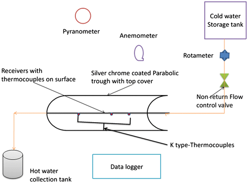
Table shows system parameters and Figure shows the experimental set-up. Three CPCs of the same size were tested simultaneously. Prototypes consist of a line focusing CPC with two kinds of receiver (copper and mild steel) coated with two types of receiver-selective coatings (black copper, black zinc). The water running in the receiver is supplied from a storage tank of 100 L capacity. The water has been circulated through the receiver tubes by siphon, i.e. natural circulation. A rotameter at the inlet was used to measure the mass flow rate of cold water entering the horizontal receiver. The temperatures of the water inside the receiver tube are measured using K-type thermocouples at four locations (including the outlet). The flow has been kept constant for the complete period of experimentation on a given day. The hot water has been stored in an insulated tank, kept near the outlet. The wind speed measurements have been taken using the wind sensor at a fixed location near the collector plane. The flow of working fluid in the receiver is shown in Figure . The data logger is used to measure environmental parameters, solar radiation, wind velocity and measurable parameters, receiver surface temperatures and fluid temperatures, which are measured at an interval of half an hour while experimentation. For the proposed system, thermal performance and heat losses are estimated at steady state.
Table 1. System parameters.
Figure 1. Experimental set-up for evaluation of thermal performance.
3. Calculations
During experimentation, the performance of CPT is evaluated with the assumption that the solar radiation is same along the length of CPT and negligible radiation drop because of absorber tube and glass. The analysis of CPT is done by studying the energy balance equation on an elementary slice dx of receiver tube, at a distance x from the inlet, yields following Equation (1) (Duffie and Beckman Citation2006; Garg and Prakash Citation2000; Goswami, Kreith, Kreider Citation2003) for steady state(1)
Equation (2) (Duffie and Beckman Citation2006; Garg and Prakash Citation2000; Goswami, Kreith, Kreider Citation2003) describes the solar flux (Sabs) on the collector.(2)
The useful heat gained by water flowing through the receiver tube is given by Equations (3) and (4) (Duffie and Beckman Citation2006; Garg and Prakash Citation2000; Goswami, Kreith, Kreider Citation2003)(3)
(4)
Equation (4) is equivalent to Hottel–Whiller–Bliss Equation for flat plate collector in which heat removal factor can be defined by equation (Duffie and Beckman Citation2006; Garg and Prakash Citation2000; Goswami, Kreith, Kreider Citation2003)(5)
where FC′ is the collector efficiency factor which can be evaluated by Equation (6) (Duffie and Beckman Citation2006; Garg and Prakash Citation2000; Goswami, Kreith, Kreider Citation2003)(6)
The instantaneous collector efficiency can be given by Equation (7) (Duffie and Beckman Citation2006; Garg and Prakash Citation2000; Goswami, Kreith, Kreider Citation2003)(7)
3.1. Calculation of heat loss coefficient
To perform thermal analysis of CPT, it is necessary to evaluate the heat loss coefficient for trough covered with glass cover. In case of CPT, a major portion of heat loss takes place from top of glass; hence, the top heat loss coefficient contributes a major part of total heat loss. As the bottom and side losses are very small quantities, they are neglected. In the present study, the overall heat loss coefficient is nothing but the top heat loss coefficient for CPT.
3.1.1. Calculation of heat loss coefficient for CPT with glass cover
Evaluation procedure of heat loss coefficient is very tedious and iterative. Based on a large number of cases, scientists have developed empirical correlation to calculate heat loss by simple equations. Empirical equation suggested by Malhotra, Garg, Palit (Citation1981)
where,(8)
(9)
(10)
(11)
L = spacing, M = 1(No. of covers)
Assumptions for using Equation (8) are
320 K < TR < 420 K, 260 K < Ta < 310 K, 0.1 < £p < 0.95, 0 < v < 10 m/s, 1 < M < 3, 0 < β < 90°.
3.1.2. Convective heat transfer coefficient
Convective heat transfer coefficient depends on properties of fluids and mean temperature receiver tube. Nusselt number and convective heat transfer coefficient can be calculated by Equations (12) and (13) (Garg and Prakash Citation2000)(12)
(13)
4. Uncertainty analysis
The errors occurred in measuring the instruments are calculated in this section. Thermocouples, pyranometer, cup-type wind sensor, data logger and rotameter are used for measuring temperature, solar intensity and wind velocity, recording of continuous data and mass flow rate, respectively. The minimum error occurred in any instrument is calculated by the ratio between its least count and minimum value of the output measured. The accuracies of various measuring instruments used in the experiments are given in Table .
Table 2. Uncertainty analysis.
5. Results and discussions
5.1. Temperature gradient model
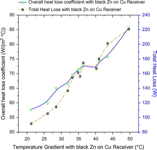
The simple relationship between receiver temperature, total heat loss and temperature gradient have been formed using regression. The temperature gradient is the difference between inlet and outlet water temperatures at the instant and this temperature gradient is taken at steady state. The model Equation (A) for black copper coating on copper receiver predicts that if the receiver temperature and total heat loss increases by 0.87 °C and 0.0318 W/m, respectively, then the temperature gradient increases by 1 °C. For black copper-coated mild steel receiver, temperature shows a negative trend as per Equation (B). The reason for this trend is as mild steel receiver heats, it loses a significantly higher amount of useful heat that can be converted into larger temperature gradients. Thus, for black copper-coated mild steel, if the receiver temperature decreases and total heat loss increases by 0.40 °C and 0.244 W/m, respectively, then the temperature gradient increases by 1 °C. For black zinc-coated copper receiver, Equation (C) predicts that if the receiver temperature and total heat loss increases by 0.45 °C and 0.11 W/m, respectively, then the temperature gradient increases by 1 °C. Figures show the variation of temperature gradient for different receiver-selective coatings and receiver material combination.(A)
(B)
(C)
Figure 2. Variation of overall heat loss coefficient and total heat loss with temperature gradient for black Cu-coated Cu receiver.
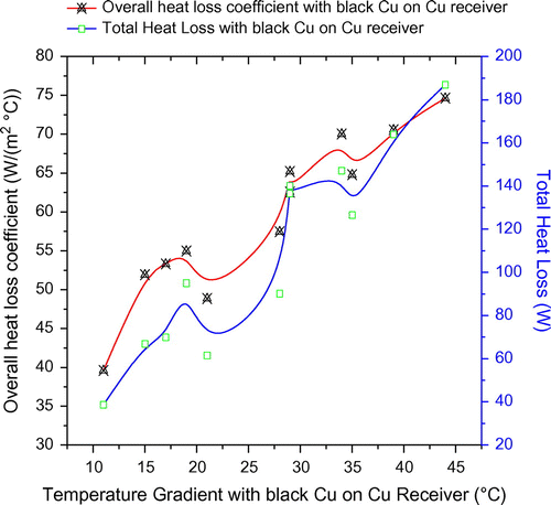
Figure 3. Variation of overall heat loss coefficient and total heat loss with temperature gradient for black Cu-coated M.S receiver.
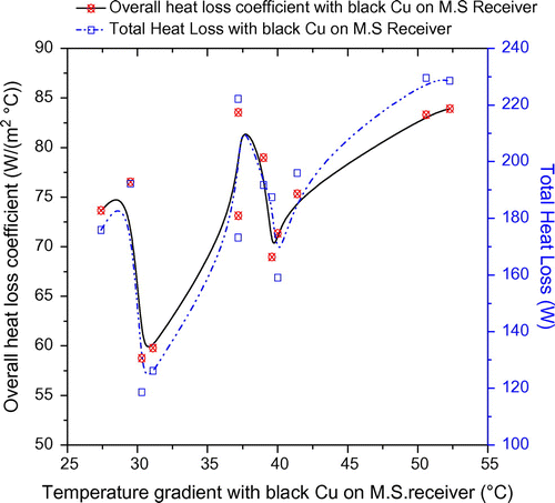
Figure 4. Variation of overall heat loss coefficient and total heat loss with temperature gradient for black Zn-coated Cu receiver.
5.2 Heat loss model
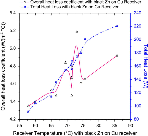
Figures show the variation of total heat loss for different receiver-selective coatings and receiver material combination. All three models Equations (D), (E) and (F) predict the positive relationship of total heat loss with the overall heat loss coefficient for receiver material-selective coatings combination. These equations predict that as overall heat loss and receiver temperature increases, total heat loss from the receivers’ increases. Total heat loss and overall heat loss coefficients have been calculated at steady state for instantaneous conditions. Model Equations (D)–(F) predict a positive relation of total heat loss with overall heat loss coefficient. From Equation (D), it is clear that when the receiver temperature increases by 4.77 °C and overall heat loss coefficient increases by approximately 7.38 W/(m2.°C), then the total heat loss will increase by 1 W/m for a black copper-coated copper receiver. For black copper-coated mild steel receiver, model Equation (E) interprets that when the receiver temperature increases by2.9 °C and overall heat loss coefficient increases by approximately 51 W/(m2.°C), then the total heat loss will increase by 1 W/m. For black zinc-coated copper steel receiver, model Equation (F) interprets that when the receiver temperature increases by 4.98 °C and overall heat loss coefficient increases by approximately 2.3 W/(m2.°C), then the total heat loss will increase by 1 W/m. Despite negative intercept, the predictions of the model are quite reasonable.(D)
(E)
(F)
Figure 5. Variation of the overall heat loss coefficient and total heat loss with receiver temperature for black Cu-coated Cu receiver.
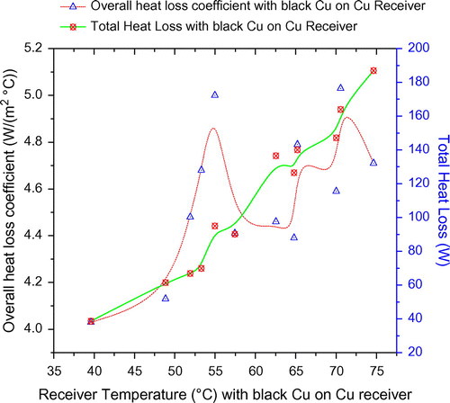
Figure 6. Variation of the overall heat loss coefficient and total heat loss with receiver temperature for black Cu-coated M.S receiver.
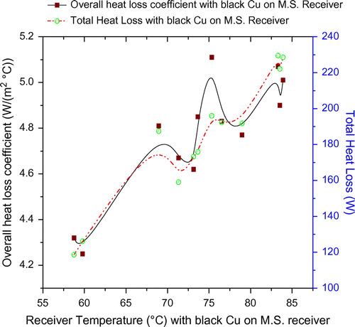
Figure 7. Variation of the overall heat loss coefficient and total heat loss with receiver temperature for black Zn-coated Cu receiver.
5.3. Efficiency model
The model of collector efficiency with receiver temperature and total heat loss indicates that there is a negative impact of an increase in the total heat loss and receiver temperature on efficiency. Total heat loss and collector efficiency have been calculated at steady state for instantaneous receiver temperature. Figures show the variation of efficiency for different receiver-selective coatings and receiver material combination. From Equation (G), it is clear that when the receiver temperature increases by 0.020 °C and total heat loss coefficient increases by approximately 1.19 W/m, then the collector efficiency will decreases by 1% for a black copper-coated copper receiver. For black copper-coated mild steel receiver, model Equation (H) interprets that when the receiver temperature increases by 0.0076 °C and total heat loss coefficient increases by approximately 3.16 W/m, then the collector efficiency will decrease by 1%. For black zinc-coated copper steel receiver, model Equation (I) interprets that when the receiver temperature increases by 0.0063 °C and total heat loss coefficient increases by approximately 1.67 W/m, then the collector efficiency will decrease by 1%(G)
(H)
(I)
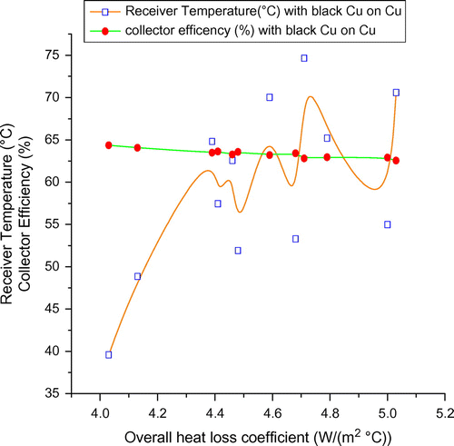
Figure 8. Variation of collector efficiency and receiver temperature with the overall heat loss coefficient for black Cu-coated Cu receiver.
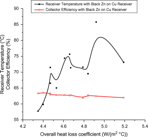
Figure 9. Variation of collector efficiency and receiver temperature with the overall heat loss coefficient for black Cu-coated M.S receiver.
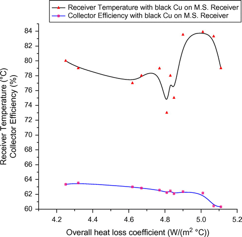
Figure 10. Variation of collector efficiency and receiver temperature with the overall heat loss coefficient for black Zn-coated Cu receiver.
6. Conclusions
A CPT system for industrial heating for which theoretical efficiency model shows that there is a difference in the efficiencies achieved with different receivers. From actual field experimentation, it has been concluded that the efficiency of the CPT system achieved with copper receiver coated with black copper is comparatively higher than the other two types of receivers.
The theoretical temperature gradient model shows that there is a difference in the receiver temperatures achieved with different receivers. From actual field experimentation, it has been observed that the receiver temperature achieved with mild steel receiver coated with black copper is comparatively higher than the other two types of receivers.
The heat loss model predicts that the total heat loss from the receivers adversely affects the overall efficiency of the system. Actual field experiments confirm the same. It has been seen that the heat losses with black copper-coated mild steel receiver are quite higher as compared to copper receiver coated with black copper and black zinc-coated copper receiver.
The experimental results are evaluated for the validity of the three regression models by comparison of the theoretical results with experimental results which demonstrates a good agreement; hence can be considered for design purpose and evaluation of thermal performance of the similar systems with different permutations and combinations. The paper proposes a simple regression analysis method to correlate thermal performance parameters for CPT and characterizing CPT systems; however, further experimentation and investigation is needed to know in detail about their role. With the models proposed in this paper, it is possible to determine the thermal performance of CPT and the correlated value thermal performance parameters are valid for water-like fluid only.
| Nomenclature | ||
| ω | = | Hour angle |
| Φ | = | Rim angle |
| (Τα)bn | = | Transmittance absorptance product of the receiver glass envelope |
| τ | = | Glass transmitivity |
| σ | = | Stefan–Boltzmann constant (5.67 × 10⁻⁸ W/(m2 °C4)) |
| ρ | = | Specular reflectance |
| θi | = | Angle of incidence of central solar ray with collector aperture, (deg) |
| ηcol | = | Solar collector instantaneous efficiency |
| ε | = | Thermal emittance |
| δ | = | Declination angle |
| γ | = | Intercept factor |
| β | = | slope (rad) |
| α | = | Absorptance |
| α | = | Solar altitude angle |
| w | = | Width of trough (m) |
| V | = | Wind speed (m/s) |
| Ul | = | Heat loss coefficient |
| Tsky | = | Sky temperature (°C) |
| TR | = | Mean temperature of tube surface (°C) |
| to | = | Outlet temperature of water (°C) |
| ti | = | Inlet temperature of water (°C) |
| Tc | = | Glass cover temperature (°C) |
| Ta | = | Atmospheric temperature of air (°C) |
| Sabs | = | Absorbed solar flux (W/m2) |
| rbn | = | Conversion factor for beam radiation |
| Ql | = | Heat loss (W/m) |
| ɸ | = | Latitude angle |
| Nu | = | Nusselt Number |
| n | = | Number of day in year |
| ṁ | = | Mass flow rate (kg/s) |
| l | = | Length of tube (m) |
| k | = | Thermal conductivity (W/(m°C)) |
| Ibn | = | Incident beam radiation (W/m2) |
| hw | = | Convective heat transfer coefficient between cover to atmosphere (W/(m2 °C)) |
| hu | = | Rate of useful heat gain (W) |
| hp-c | = | Convective heat transfer coefficient between tube to cover (W/(m2 °C)) |
| hf | = | Convective heat transfer coefficient (W/(m2°C)) |
| Fr | = | Heat removal factor |
| FC′ | = | Collector efficiency factor |
| F | = | Focal length of parabola (m) |
| dout | = | Outer diameter of receiver tube (m) |
| Di | = | Inner diameter of receiver tube (m) |
| D | = | Diameter of absorber tube(m) |
| Cpw | = | Specific heat of water at constant pressure(J/kg K) |
| C | = | Concentration ratio |
| Aabs | = | Area of receiver(m2) |
| A | = | Area of collector (m2) |
Disclosure statement
No potential conflict of interest was reported by the authors.
References
- Bakos, G. C., I. Ioannidis, N. F. Tsagas, and I. Seftelis. 2001. “Design, Optimisation and Conversion Efficiency Determination of a Line-Focus Parabolic-trough Solar-collector (PTC).” Applied Energy 68: 43–50. doi:10.1016/S0306-2619(00)00034-9.
- Duffie, J., and W. Beckman. 2006. Solar Engineering of Thermal Processes. New York: John Wiley and Sons.
- Eck, M., and E. Zarza. 2006. “Saturated Steam Process with Direct Steam Generating Parabolic Troughs.” Solar Energy 80 (11): 1424–1433. doi:10.1016/j.solener.2006.03.011.
- García, Fernández, E. Zarza, L. Valenzuela, and M. Pérez. 2005. “Parabolic-trough Solar Collectors and Their Applications.” Renewable and Sustainable Energy Reviews 14 (7): 1695–1721. doi:10.1016/j.rser.2010.03.012.
- Garg, H. P., and J. Prakash. 2000. Solar Energy Fundamentals and Applications. 1st ed. New Delhi: Tata-McGraw-Hill.
- Gong, Guangjie, Xinyan Huang, Jun Wang, and Menglong Hao. 2010. “An Optimized Model and Test of the China’s First High Temperature Parabolic Trough Solar Receiver.” Solar Energy 84 (12): 2230–2245. doi:10.1016/j.solener.2010.08.003.
- Goswami, Yogi, F., Kreith, and J. F. Kreider. 2003. Principals of Solar Engineering. Philadelphia, PA: Taylor and Francis.
- Gudekar, Ajitkumar S., Atul S. Jadhav, Sudhir V. Panse, Jyeshtharaj B. Joshi, and Aniruddha B. Pandit. 2013. “Cost Effective Design of Compound Parabolic Collector for Steam Generation.” Solar Energy 90 (4): 43–50. doi:10.1016/j.solener.2012.12.020.
- Hachicha, A. A., I. Rodríguez, R. Capdevila, and A. Oliva. 2013. “Heat Transfer Analysis and Numerical Simulation of a Parabolic Trough Solar Collector.” Applied Energy 111: 581–592. doi:10.1016/j.apenergy.2013.04.067.
- Huang, Weidong, Peng Hu, and Zeshao Chen. 2012. “Performance Simulation of a Parabolic Trough Solar Collector.” Solar Energy 86(2): 746–755. doi:10.1016/j.solener.2011.11.018.10.1016/j.solener.2011.11.018
- Kalogirou, Soteris A. 2012. “A Detailed Thermal Model of a Parabolic Trough Collector.” Energy 48(1): 298–306. doi:10.1016/j.energy.2012.06.023.10.1016/j.energy.2012.06.023
- Lei, Dongqiang, Qiang Li, Zhifeng Wang, Jian Li, and Jianbin Li. 2013. “An Experimental Study of Thermal Characterization of Parabolic Trough Receivers.” Energy Conversion and Management 69: 107–115. doi:10.1016/j.enconman.2013.02.002.
- Malhotra, A., H. P. Garg, and A. Palit. 1981. “Heat Loss Calculation of Flat Plate Solar Collectors.” Journal of Thermal Energy 2 (2): 59–62.
- Sagade, A. A. 2015. “Experimental Investigation of Effect of Variation of Mass Flow Rate on Performance of Parabolic Dish Water Heater with Non-coated Receiver.” International Journal of Sustainable Energy.34 (10): 645–656. doi:10.1080/14786451.2013.855777.
- Sagade, A. A., N. N. Shinde, and P. S. Patil. 2014. “Effect of Receiver Temperature on Performance Evaluation of Silver Coated Selective Surface Compound Parabolic Reflector with Top Glass Cover.” Energy Procedia 48:212 –422. doi:10.1016/j.egypro.2014.02.026.10.1016/j.egypro.2014.02.026
- Singh, H., and P. C. Eames. 2012. “Correlations for Natural Convective Heat Exchange in CPC Solar Collector Cavities Determined from Experimental Measurements.” Solar Energy 86 (9): 2443–2457. doi:10.1016/j.solener.2012.05.014.
- Skeiker, Kamal. 2009. “Optimum Tilt Angle and Orientation for Solar Collectors in Syria.” Energy Conversion and Management 50 (9): 2439–2448. doi:10.1016/j.enconman.2009.05.031.
- Souliotis, M., P. Quinlan, M. Smyth, Y. Tripanagnostopoulos, A. Zacharopoulos, M. Ramirez, and P. Yianoulis. 2011. “Heat Retaining Integrated Collector Storage Solar Water Heater with Asymmetric CPC Reflector.” Solar Energy 85 (10): 2474–2487. doi:10.1016/j.solener.2011.07.005.
- Thomas, A., A. Satish, and S. A. Thomas. 1994. “Design Data for the Computation of Thermal Loss in the Receiver of a Parabolic Trough Concentrator.” Energy Conversation and Management 35 (7): 555–568. doi:10.1016/0196-8904(94)90038-8.
- Thomas, A., and H. M. Guven. 1993. “Parabolic Trough Concentrators Design, Construction and Evaluation.” Energy Conversion and Management 34 (5): 401–416. doi:10.1016/0196-8904(93)90090-W.
- Tsai, Chung-Yu, and Psang Dain Lin. 2012. “Optimized Variable-focus-parabolic-trough Reflector for Solar Thermal Concentrator System.” Solar Energy 86 (5): 1164–1172. doi:10.1016/j.solener.2012.01.009.
- UNDP and Ministry of New and Renewable Energy, Government of India. 2013. Market Development and Promotion of Solar Concentrators Based Process Heat Application in India: A Factsheet. New Delhi: UNDP Office.