Abstract
In Brazil, there are few studies investigating the performance and guidelines parameters of solar light pipes from the national perspective. This paper aims to analyse the performance of a solar light pipe prototype installed in a test house in the city of Curitiba/PR, Brazil and to indicate a set of parameters for the design of solar light pipes for the Brazilian social housing context. The performance of a solar light pipe provided with different lighting devices to control and redirect light was analysed. The best performance for diffusers was obtained during partially covered skies. Light redirection devices presented the best efficiency during clear sky conditions with direct sunlight, on working-planes closer to the prototype. The developed prototype with the lighting control devices produced a considerably enhanced lighting performance, complementing natural lighting in indoor environment. Based on the results, recommendations and guidelines to enhance solar light pipe configurations are proposed.
1. Introduction
In the current global context of increasing energy demand, the use of new technologies that can contribute to reduce electricity consumption is highly recommended. To satisfy the high demand of energy in Brazil, the deployment of new technologies with low environmental impact will be required (EPE Citation2012).
It has been noticed that Brazil receives more solar irradiation than many countries that are in the forefront of utilizing solar energy technologies. Solar irradiation values in Brazil vary between 4200 and 6700 kWh/m2 for any region of the country (Pereira et al. Citation2006). These values are higher than solar irradiation in the European Union countries, such as Germany (900–1250 kWh/m2) and Spain (1200–1850 kWh/m2), where projects for harnessing solar energy are widespread (Pereira et al. Citation2006). In Brazil, few research projects are focused on how to utilize the power of sunlight on applications that enhance natural lighting: most projects focus on the utilization of solar power to generate electricity and heating water (Souza Citation2005; Purim Citation2008).
Advanced daylighting technologies are alternatives that contribute to the reduction of energy spent on lighting, while they also mitigate carbon emissions associated with artificial lighting systems. One natural illumination technology is the solar light pipe. This technology can considerably increase lighting levels in indoor environments, and significantly contribute to reduce the use of artificial lighting during daytime (Mohelnikova Citation2009; Kim and Kim Citation2010; Li et al. Citation2010; Mayhoub and Carter Citation2012). When used integrated with traditional vertical windows, these systems can provide adequate daylight in areas farther from the windows, where daylight levels decrease (Souza Citation2005; Li et al. Citation2010).
The recommendations in the technical literature for solar light pipes are focused on calculations of solar light pipe performances, considering mathematical models and formulas from the analysis of geometric and environmental parameters (Mohelnikova Citation2009; Komar and Darula Citation2012; Kocifaj et al. Citation2012). However, there are few recommendations and design parameters for solar light pipe configurations to improve this technology within the Brazilian context. Also there are few published studies on the use and integration of these systems in the built environment (Toledo, Busch, and Pelegrini Citation2012).
The paper describes an experimental test conducted with a solar light pipe installed in a “test house” that mimics a typical Brazilian social dwelling for low-income families in the city of Curitiba/PR. To investigate the possible application of these technologies in the Brazilian context, this paper aims to analyse the performance and indicate a set of design parameters for solar light pipes for the Brazilian social housing context.
2. Solar light pipe configuration parameters
Tubular light guides have found practical application in many buildings because they improve lighting levels in indoor environments (Mohelnikova Citation2009). Solar light pipes are novel technologies consisting of a light collector, a tube with high reflective inner surface and a diffuser. This system collects daylight and transfers it into building interiors (Verso, Pellegrino, and Serra Citation2011; Komar and Darula Citation2012). This technology is based on light pipes equipped with optical devices to collect both diffuse skylight and direct sunlight. Inside the tube, multiple specular and diffuse inter-reflections occur before the light reaches the diffuser. The diffuser distributes reflected daylight over the interior space (Mohelnikova Citation2009; Kim and Kim Citation2010; Verso, Pellegrino, and Serra Citation2011).
Solar Light guides transmit natural light under various daylight conditions during clear, overcast or cloudy skies, with different sky luminance distribution and sunlight intensity during any day of the year (Kim and Kim Citation2010; Komar and Darula Citation2012). Other technologies have been developed to enhance light transmission efficiency, the transmission performance of the technologies increases when direct sunlight can be collected and redirected along the pipe (Verso, Pellegrino, and Serra Citation2011).
General recommendations and parameters to improve solar light pipe performances were summarized based on technical literature and on recommendations from commercial companies in the market. Figure presents these parameters, but it should be emphasized that light guide transmission efficiency depends on the geometrical and optical guide parameters as well as on the sky luminance conditions (Komar and Darula Citation2012).
Figure 1. Geometric and environmental parameters that influence the performance of solar light pipes. Source: Adapted from Mohelnikova (Citation2009), Kocifaj et al. (Citation2012), Komar and Darula (Citation2012), Kim and Kim (Citation2010), Xifra and Evans (Citation2002).
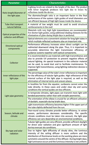
In the international technical literature, recommendations and parameters for configuration of light pipes to enhance performance are widely discussed. Many of the published reports explain different methods and procedures to calculate the performance of these systems. There is a technical Standard Report published by the International Commission on Illumination, and the report includes a contextual review of the technology of all generic types of daylight guidance systems (CIECitation2006). The sections relate to performance indices, photometry of components and systems, design methods, cost, benefits, human factors and architectural issues (CIE Citation2006). To conduct this study this report was considered.
The parameters explained in Figure are general guidelines for solar light pipes. For more sophisticated models, collectors can be equipped with heliostats and sun-tracking mirrors to maximize the contribution of direct sunlight. The resulting active systems provide better performance under clear sky conditions rather than in overcast conditions, thus they are most useful in climates where sunny skies are predominant (Verso, Pellegrino, and Serra Citation2011). Hybrid systems allowing to simultaneously deliver daylight and electric light into buildings through luminaire-like output devices have recently been developed (Verso, Pellegrino, and Serra Citation2011). A comprehensive overview on available passive and active technologies can be found in literature (Mayhoub and Carter Citation2010).
With time, with more complex and sophisticated types offered in the market, the key factor is data describing their photometric performances in terms of global light transmission efficiency: from the point of view of designers. Suitable and simple tools are needed from the earliest design stage and throughout the design process to predict the daylight availability in an interior space and to predict the number of pipes needed to produce a minimum natural light illuminance according to standard requirements (Verso, Pellegrino, and Serra Citation2011).
3. Methodology
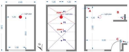
For this research, a light pipe prototype was developed and installed in a test house located at the Polytechnic Campus of Federal University of Paraná, sited in the city of Curitiba, Brazil. The latitude and longitude of this city is −25.51° and −49.27°. The azimuth that corresponds to this test house is 21°. The prototype is divided into three main parts: the collector, the transportation system and the lighting control system (Figure ). The prototype’s upper part, the collector, was cut at an angle of 30° and directed towards the North to optimize sunlight capture (Kocifaj et al. Citation2012). No active system in the collector was used to maximize lighting transmission; also, no lighting redirection device was installed. The prototype was constructed without sophisticated technology and at a low cost.
For this research, no light redirection devices or applications or any other technologies as heliostats were considered. The focus on this work was lighting manipulation devices next to the diffuser. It is important to emphasize that any optical device is installed in the inner part of the tube.
The collector and the diffuser were made of polycarbonate with UV protection and with 89% transmittance. The aluminium pipe was internally coated with a Mylar® sheet with 98% reflectance. The ratio diameter/length is 1:3, the tube length L = 75 cm and the diameter φ = 25 cm (Figure ). The geometry of all components corresponded to previous research using computer simulations. Based on previous work, a lighting control system was proposed to control natural lighting levels in the room and to avoid visual discomfort. The purpose of this control lighting system was to compare the lighting levels in the room without the use of the light pipe and using the diffuser with less transmittance percentage.
A lighting control system with devices allowing regulation of daylight entering to the room was configured (Figure (a)). The device in a totally open setting would serve at time when maximum transmitted light is required (Figure (a)). This scenario is expected under overcast sky conditions. To regulate lighting levels, a device that gives the option to partially close the lighting entering the room was added, this device has 50% transmittance (Figure (b)). This element can be used in periods where lighting levels could cause some visual discomfort, during time of direct sunlight. When the device is closed, all daylight is blocked (Figure (c)). This last option is expected to be useful in moments when lighting levels are high and the lighting through window is sufficient.
Figure 2. Lighting control system. (A) 89 % transmittance, (B) 50 % transmittance, (C) Blocked daylight.

For the prototype, two light redirection devices were also configured. The purpose of the devices was to redirect natural lighting to other working-planes. These devices were proposed with the aim to capture lighting in moments of high direct sunlight. This additional lighting can be used in working planes besides the working plane below the solar light pipe. During these periods, lighting through the window could be sufficient in the working plane area below the prototype, making it possible to take advantage of this extra natural lighting.
These devices are not fixed to the total control device. It is an element that can be used when required by the user. The first device is a piece of 10 × 20 cm, with an angle of 30° with respect to the y axis (Figure (a)). The second device is larger, covering more area of the diffuser. In this piece was given two angles: the first angle is 30° with dimensions of 25 × 25 cm with respect to the y-axis. The second angle is 30° with respect to the y-axis, the device dimensions are 25 × 15 cm (Figure (c)). Both devices are coated with an adhesive sheet with 95% reflectance.
The test room where the measurements were carried out have the following dimensions: (3.82 × 2:40 × 2.60) m, and the percentage of window area on the facade is 30%. Other variables in the room are: floor reflectance 45%, ceiling reflectance 25% and walls reflectance 70%, window transmittance 88%. It is important to emphasize the presence of the window in the room as this contributes significantly to lighting levels. The central axis of the solar light pipe prototype is located at 2.82 m from the window in y-axis and at 1.2 m with respect to x-axis. Two analysis points were established for the measurements, located at 75 cm height from the floor level (Figure ). Four sensor Lux metres (LX1330B model) were used. Uncertainty in measurement is defined by accuracy of lux metres that varies between ±3 and ±5%.
The lux metres were positioned at points P1, P2, P3 and P4 as illustrated in Figure . The prototype has a higher lighting efficiency at points 1 and 2. Due to the presence of the window, lighting levels in the area near the window are more influenced by the amount of light from this window. For this reason, analysis used 2 values: average values from points P1 and P2 and points P3 and P4 (Figure ). Point 1 and Point 2 belong to zone 1, and Point 3 and Point 4 belong to zone 2.
For analysis of the performance of the light redirection devices, measurements were recorded at three points (A, B, C). The sensors were located at a height of 75 cm from the floor in three different working planes. Point A is the only one that belongs to the room of 2.4 × 3.80 m (Figure ) of measurements explained before, this is the closest point from the prototype. Point B is located near the x-axis of the prototype. The Point C is the farthest from the light pipe, and is located 15 cm from one wall of the test house (Figure ). The purpose to select the three points in the room was to study illuminance levels in three different working planes with different influence of lighting from the window and the solar light pipe. Point A receives more light from the prototype, and also receives light from the window, but at low intensity. Point B is more isolated and barely receives light from the window, and obtains more daylight from the prototype. Lighting values at Point C are influenced more by the window than by the prototype (Figure ).
The field-measurements were performed between 7 am and 4 pm, between June 2013 and August 2013, winter season in Curitiba-Brazil. The external illuminance was recorded with an outdoor sensor. The daylight availability depends on the sky conditions (Li et al. Citation2010). For this study, sky conditions are categorized into three types: overcast, partly cloudy and clear skies.
The experimental tests with the solar light pipe were conducted in a “test house” that mimics a typical Brazilian social dwelling for low-income families. Therefore, the physical size of the room, as well as the selected interior materials aimed to provide an environment as close as possible to this context.
Based on the results of all the measurements, parameters and recommendations to improve solar light pipe performance were determined. These guidelines will be based on the performance analysis of devices that only manipulate lighting from the diffuser. As mentioned before, no additional devices in the inner tube or in the collector were installed.
4. Results
4.1. Performance comparison of the lighting control devices
From all analysed days, an average of the measurements were taken according to each sky type, and results were grouped in days that correspond to overcast, partially covered and clear sky. Because solar light pipes have a higher influence on lighting at points 1 and 2 on the working plane, an average of illuminance values of these points was obtained. Average values of illuminances in Points P3 and P4 were taken separately.
Figure shows average of zone 1 (P1 and P2) of all days when illuminances were recorded. In Figure , the blue lines are values using the prototype with the diffuser closed, and the room receiving natural lighting only through the window. The green lines are values using the diffuser with 50% transmittance. The red lines are illuminance values with the control device totally open, with the clear diffuser and daylight from the window.
Figure 5. Average of the illuminance values in zone 1 for the three sky types. (a) Overcast sky, (b) Partially covered sky, (c) Clear sky.
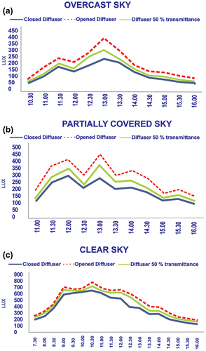
For zone 1, all the clear diffuser had higher illuminance levels in comparison with diffuser with 50% transmittance during all sky conditions. With the clear diffuser, values increase up to 163 lux, an equivalent of 72%, in comparison with the diffuser closed. These results correspond to covered sky conditions (Figure ).
For partially covered sky in zone 1, the highest increase was 162 lux using the clearest diffuser in comparison with the diffuser closed, this value is equivalent to a 58% increase. For clear sky conditions, an increase of 194 lux was observed, an equivalent of 49%, in comparison with the diffuser closed (Figure ). The dips observed in Figures (b) and (b) can be explained by a decrease in daylighting illuminance, caused by multiple factors such as temporal cloud covers at the time the measurements were made. These are regular climatic factors that cannot be controlled and appeared while doing the measurements.
Figure 6. Average of the illuminance values in zone 2 for the three sky types. (a) Overcast sky, (b) Partially covered sky, (c) Clear sky.
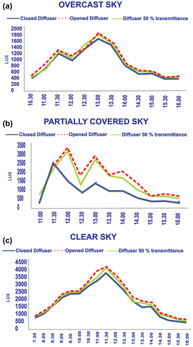
The lighting control system with semitransparent diffuser achieved its purpose and can be used when lighting levels need to be regulated. However, in days with clear sky conditions and direct sunlight, difference in lighting values between the clear diffuser and semitransparent diffuser are low (Figure ). For this reason, in days with high external illuminance in partially covered sky or clear sky conditions, the semitransparent diffuser can reduce lighting levels at certain times, where total lighting levels in the room can cause visual discomfort and glare. For covered sky conditions and partially covered with low external illuminance, the use of this diffuser is not recommended. To increase efficiency in indoors illumination distribution, material with higher transmittance percentage can be used in both diffuser and collector.
As shown in Figure , zone 2, under overcast and clear sky conditions, lighting levels do not increase much because the prototype has no big influence in areas close to the window. The highest increase during overcast conditions is 12% in illuminance values using the solar pipe in comparison with the solar light pipe closed. For Clear sky conditions this increment is equivalent to 16%. In both cases, this increment corresponds to the sun peak hours. In all cases, the difference in values for the diffuser with 50% transmittance and the clearest diffuser is low, especially during overcast and clear skies (Figure ).
A different situation was observed for partially covered sky conditions, where the lighting contribution from the light pipe is higher. Using the light pipe, lighting levels increased up to 107% (Figure ). In this case, it is important to highlight that daylight from the prototype cannot be necessary, due high values, depending on minimum lighting requirement. This fact also should be considered for clear sky conditions.
4.2. Performance of light redirection devices
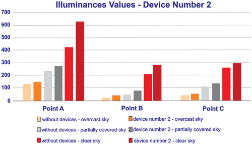
An average was taken for all days when measurements were carried out. In this case, values were grouped according to the three sky conditions: overcast, partially covered and clear sky. The averages of these results are shown in Figure . In this analysis, the hours when the highest differences were found were selected; these hours correspond to 11.00, 12.00 and 13.30 pm (Figure ). The selected hours are at the sun peak hours. Measured lighting levels decreased considerably at the end of the day. In all cases and hours, the device with larger area, device number 2 was more efficient to redirect lighting to the working planes.
Figure 7. Average illuminance values with light redirection devices; in covered, partially covered and clear sky conditions.
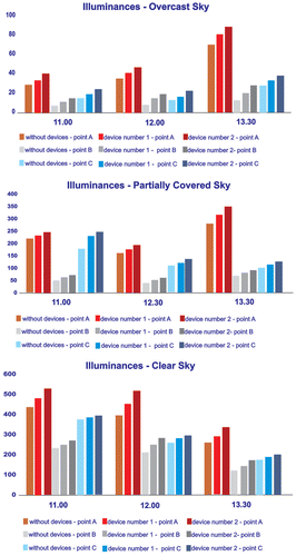
For covered sky (Figure ), neither device is very efficient. The increase on lighting levels in working-planes where the light was redirected was low. For device number 2, this increase is higher in comparison with device number 1, but is not substantial. Based on this result, the lighting redirection devices were not performing well under diffuse lighting.
For partially covered sky (Figure ), the devices perform better compared with overcast sky. For this sky condition, device number 1 with the smaller area did not meaningfully increase the lighting levels because device number 1 does not cover all the diffuser area. Hence, more light enters the room compared with device number 2. Figure shows the values on the three analysed points that correspond to the working planes.
For clear sky and direct sunlight (Figure ), both devices had a better performance in comparison with the other two sky types, the highest increase is at 12.00 pm. Values shown in Figure are the average for all days analysed in this sky condition. Higher illuminance increases are observed at points A, C and B, respectively, independent of the device used. This is explained by the distance of the points from the light pipe and the presence of the window in the room. The best performance using the devices is at Point A, and the lowest performance is measured at Point B. Likewise, the best efficiency of these devices is observed in moments when direct sunlight enters through the light pipe.
The light redirection devices that were attached at the indoors part of the light pipe functioned as expected. The highest efficiency corresponds to clear sky conditions and larger device. Figure shows a comparison of the efficiency of device number 2 for the three sky conditions. These values correspond to the day when maximum values were recorded for each sky type at 12.00 pm. This comparison was carried out for the three analysed points. Using device number 2, illuminance values in point 1 increase up to 205 lux. As mentioned, this point is located closer to the prototype than the window, but also receives a considerable amount of lighting from the window. Bars in orange, grey and red correspond to the covered, partially covered and clear skies, respectively.
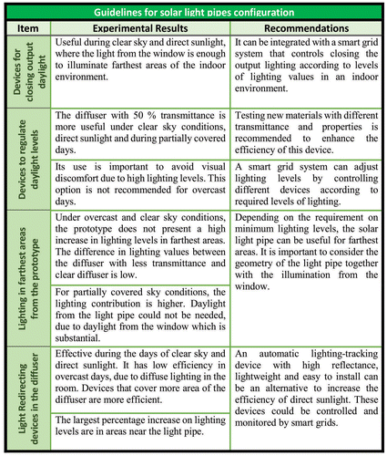
It is important to emphasize that photometric data of guidance systems are scarcely available (Verso, Pellegrino, and Serra Citation2011). Based on an analysis of all the results, guidelines and recommendations to enhance solar light pipe configurations will be presented. These recommendations are tabulated in Figure .
5. Conclusions
The data analysed in this study contributes to published data on improvement of solar light pipes. There are no specific recommendations in the literature about light redirection devices installed next to the diffuser, and the gap in this area was a factor to conduct this research. The recommendations are based on data from a city in Brazil, and results can be different for diverse geographic locations (Mayhoub and Carter Citation2011).
Performance of a solar light pipe prototype, with different lighting control devices, integrated with lighting from a simple window was analysed in the city of Curitiba, Brazil. The diffuser with more transmittance was the most efficient in all cases. For partially covered sky, the best efficiency was obtained in the zone 1 that is near the prototype. The diffuser with less transmittance could be used in days with direct sunlight and clear sky, to avoid higher lighting levels that cause visual discomfort in indoor environments. Contribution on lighting levels in farthest areas from the light pipe is low, especially under overcast sky conditions. For partially covered sky, lighting levels increase up to 107%. Performances of two light redirection devices located next to the diffuser were also analysed. For overcast sky conditions, the efficiency was lower, the device with shorter dimensions had the lowest performance in all analysed cases. The best efficiency was for the device with larger area, and for clear sky conditions with direct sunlight, reaching an increase up to 205 lux in a working-plane that is closer to the prototype. In other seasons as winter, this increment on lighting can be higher. All the devices proposed in the prototype can be manipulated depending on minimum lighting required in the room or according to user necessities. A light-pipe system integrated with proper lighting controls can substantially reduce the lighting energy use (Li et al. Citation2010).
It is important to notice that the weather and environmental conditions were not favourable during the study because measurements were carried out during the winter season. Despite this fact, the developed prototype with all the lighting control devices produced a considerable enhanced lighting performance, complementing natural lighting in the indoor environment. Low reflectance values on the ceiling and walls in the room of the test house must be also considered.
The established guidelines in this study can serve as a basis for further work in this area of research. In a future paper, the topic of how to decouple the window daylight from the solar light pipe daylight will be studied.
The prototype developed in the research is a low-cost product and does not have a sophisticated technology. Further studies on improving the efficiency on lighting control devices with sophisticated alternatives and integrating active systems should be conducted. In addition, controlling all devices with smart grids should be considered. Likewise, new research on performance of these systems in other climatic conditions in Brazil and other countries should be performed.
Disclosure statement
No potential conflict of interest was reported by the authors.
References
- CIE – International Commission on Illumination 2006. CIE 173: 2006. Tubular Daylight Guidance Systems. Technical Report. Vienna: CIE Central Bureau.
- EPE – Energy Research Company 2012. “Projection of Electricity Demand for the Next 10 Years (2013–2022).” Accessed January 7, 2013. http://www.epe.gov.br/mercado/Documents/S%C3%A9rie%20Estudos%20de%20Energia/20130117_1.pdf
- Kim, G., and J. Kim. 2010. “Overview and New Developments in Optical Daylighting Systems for Building a Healthy Indoor Environment.” Building and Environment 45 (2): 256–269. doi:10.1016/j.buildenv.2009.08.024.
- Kocifaj, M., F. Kundracik, S. Darula, and R. Kittler. 2012. “Availability of Luminous Flux below a Bended Light-Pipe: Design Modelling under Optimal Daylight Conditions.” Solar Energy 86 (9): 2753–2761. doi:10.1016/j.solener.2012.06.017.
- Komar, L., and F. Darula. 2012. “Determination of the Light Tube Efficiency for Selected Overcast Sky Types.” Solar Energy 86 (1): 157–163. doi:10.1016/j.solener.2011.09.023.
- Li, D. H. W., E. K. W. Tsang, K. L. Cheung, and C. O. Tam. 2010. “An Analysis of Light-Pipe System via Full-Scale Measurements.” Applied Energy 87 (1): 799–805. doi:10.1016/j.apenergy.2009.09.008.
- Mayhoub, M. S., and D. J. Carter. 2010. “Towards Hybrid Lighting Systems: A Review.” Lighting Research and Technology 42 (1): 51–72. doi:10.1177/1477153509103724.
- Mayhoub, M., and D. Carter. 2011. “The Costs and Benefits of Using Daylight Guidance to Light Office Buildings.” Building and Environment 46 (3): 698–710. doi:10.1016/j.buildenv.2010.09.014.
- Mayhoub, M., and D. Carter. 2012. “A Feasibility Study for Hybrid Lighting Systems.” Building and Environment 53: 83–94. doi:10.1016/j.buildenv.2012.01.011.
- Mohelnikova, J. 2009. “Tubular Light Guide Evaluation.” Build Environment 44 (10): 2193–2200. doi:10.1016/j.buildenv.2009.03.015.
- Pereira, E. B., F. R. Martins, S. L. Abreu, and R. Ruther. 2006. Brazilian Solar Energy Atlas. 1st ed. São Jose dos Campos: INPE, SWERA.
- Purim, C. A. 2008. “Development of a Solar Collector for Direct Lighting with Fiber Optics.” Master diss., Technology development Program, Engineering Institute of Parana, Curitiba, Brazil.
- Souza, D. A. 2005. Theoretical and Experimental Performance Evaluation of Solar Light Pipes in Sao Carlos - SP. Master ., Department of Civil Engineering, Federal University of São Carlos, Brazil.
- Toledo, G. E., Busch, L. E., and Pelegrini, A.V. 2012. “Solar Light Pipe Technologies and Benefits: A Structured Literature Review Aiming to Identify Parameters and Contribute to Sustainable Design.” Proceedings of IV Parana Symposium of Sustainable Design 2012, Curitiba, Brazil, November 20, 2012.
- Verso, V. R. M., A. Pellegrino, and V. Serra. 2011. “Light Transmission Efficiency of Daylight Guidance Systems: An Assessment Approach Based on Simulations and Measurements in a Sun/Sky Simulator.” Solar Energy 85 (11): 2789–2801. doi:10.1016/j.solener.2011.08.017.
- Xifra, M. F., and J. M. Evans 2002. “Sistemas Innovativos Para El Direccionamiento De Luz Natural, Películas Holográficas Y Lumiductos” [Innovative Systems to Redirect Natural Light, Holographic Films and Light Ducts]. Avances En Energías Renovables Y Medio Ambiente [Progress in Renewable Energy and Environment] 6 (2): 901–906.


