Abstract
This is a new technique for operating a Stirling heat engine. Theoretically, its thermal efficiency should be greater than 100%. However, it does not violate the first and second laws of thermodynamics; it is not a perpetual motion engine, because the atmospheric pressure can be utilized as the external energy source, which no other existing heat engines can do. This means that the new type of heat engine can offer an immediate and concrete solution to the many energy and climate challenges that we are facing; therefore the reliability and significance of this new type of Stirling heat engine is self-evident.
1. Introduction
The Stirling cycle is composed of four heat-transfer processes: isochoric exothermic process, isothermal exothermic compression, isochoric endothermic process, isothermal endothermic expansion process (Walker Citation1980). During isothermal exothermic compression, for the existing Sterling heat engines, they need the isothermal endothermic expansion process to compress the working fluid; in fact, for all existing heat engines, the high gas is expanded which does more work than is required for the compression and results in net work output (Martini Citation1983), it means that existing heat engines need more fuel to produce net work, and the thermal efficiency of existing heat engines is low. To save fuel and to increase thermal efficiency, an external energy source is needed.
The atmospheric pressure can be utilized as the external energy sources. In 1712, Thomas Newcomen used the isochoric exothermic process and the isothermal exothermic compression process to devise an atmospheric engine, which employed both low-pressure steam and atmospheric pressure. It contained a piston that moved by an atmospheric pressure in a cylinder in which a vacuum was created, which is an isothermal exothermic compression process. The vacuum originated from the usage of the cooling water to condense the steam, which is an isochoric exothermic process (Butterman Citationn.d.).
To utilize atmospheric pressure as the external energy sources, the new type of Stirling heat engine needs an airproof container which is filled with high pressure air.
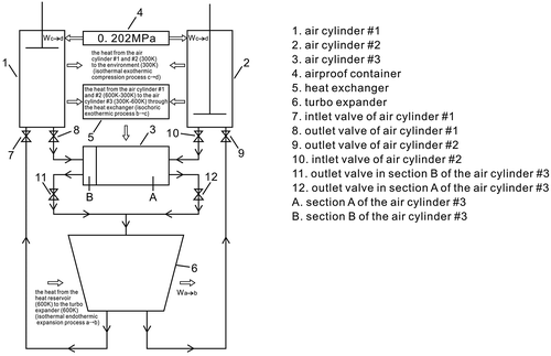
This new type of Stirling heat engine, shown schematically in Figure , has the following main parts: an airproof container, a turbo expander, three air cylinders (#1, #2 and #3), six valves, and a heat exchanger. The working fluid for this engine is air; its cycle is the same as is used, at present, in the Stirling cycle (Martini Citation1983).
When the air flows through the turbo expander, which provides an isothermal endothermic expansion process, the kinetic energy of the air will be transformed into the kinetic energy of the turbine. Air cylinder #1 and #2 are the cold cylinders, where the air will remain; air cylinder #1 and #2 are similar to the cylinders of the Newcomen atmospheric engine (Lira Citationn.d.). This is both an isochoric exothermic process and an isothermal exothermic compression process. The atmospheric pressure of the airproof container can be utilized as the external energy source by the air cylinders #1 and #2, which means that the new type of Stirling heat engine can produce more energy than the existing Stirling heat engine. The air cylinder #3 is the hot cylinder, where the air remains. This is an isochoric endothermic process, as the air cylinder #3 will extract heat from both the air cylinder #1 and the air cylinder #2 through the heat exchanger.
2. The structure and the cycle of the new type of Stirling heat engine
The working cycle for the air is comprised of two loops. The sequence is: loop 1: the turbo expander → the air cylinder #1 → the section A of the air cylinder #3 → the turbo expander; loop 2: the turbo expander → the air cylinder #2 → the section B of the air cylinder #3 → the turbo expander, as shown in Figure .
The air cylinder #1 and the air cylinder #2 are the cold cylinders; the air cylinder #3 is the hot cylinder, which will extract heat from the air cylinder #1 and the air cylinder #2 through the heat exchanger.
Let us suppose that the air is an ideal gas, the efficiency of the heat exchanger is 100%, the temperature of the hot reservoir is 600 K, the temperature of the cold reservoir is 300 K, and the pressure of the airproof container is 0.202 MPa.
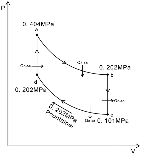
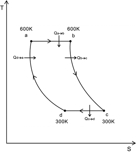
In Figures and , a → b depicts the air flowing through the turbo expander, which is an isothermal endothermic expansion process, where the kinetic energy of the air is transformed into the kinetic energy of the turbine; Ta is the temperature of the turbo expander’s inlet, Tb is the temperature of the turbo expander’s outlet, Ta = Tb = 600 K, Ta and Tb display the temperature of the heat reservoir; Pa is the pressure of the turbo expander’s inlet, Pb is the pressure of the turbo expander’s outlet. Pa = 0.404 MPa, Pb = 0.202 MPa.
When the air leaves the turbo expander it enters the air cylinder #1, where the inlet and outlets are equipped with valves and a piston moves along the air cylinder #1. The structure of the air cylinder #2 is the same as that of the air cylinder #1.
The air cylinder #1 and the air cylinder #2 are connected to an airproof container, which is filled with high pressure air. The atmospheric pressure of the airproof container, shown as Pcontainer, is equal to that of the outlet of the turbo expander, where Pcontainer = Pb = 0.202 MPa.
At the beginning of the cycle, the piston is at the bottom of air cylinder #1, whose inlet opens and connects to the outlet of the turbo expander. The piston is then pushed towards the top of the air cylinder #1. This movement is similar to that of the intake stroke of the Otto cycle. When the piston reaches the top of the air cylinder #1, the air will then enter this air cylinder. The inlet valve then closes. The piston remains in a fixed position at the top of the air cylinder #1, and then the inlet to this cylinder is disconnected from the outlet of the turbo expander.
The air cylinder #2 undergoes the same processes during loop 2.
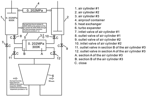
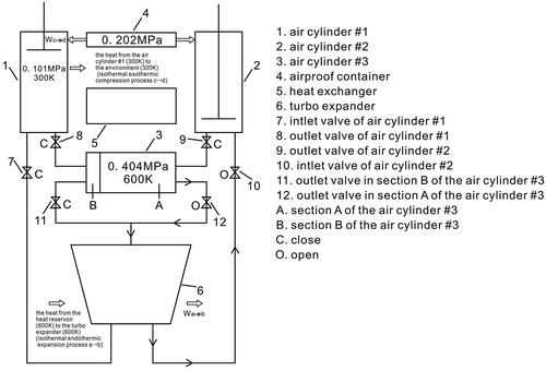
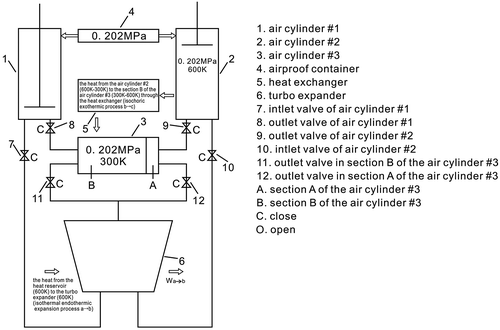
This is stage 1. Now the air cylinder #1 is filled with air whose the temperature is 600 K and whose pressure is 0.202 MPa, and the section A of the air cylinder #3 is filled with air whose temperature is 300 K and whose pressure is 0.202 MPa. The piston of the air cylinder #1 remains in a fixed position at the top of the air cylinder #1. The piston of the air cylinder #2 is at the bottom of air cylinder #2, and the piston of the air cylinder #3 is at the far left side of the air cylinder #3. There is no air remaining in the air cylinder #2 and the section B of the air cylinder #3; all valves will close, and then the section A of the air cylinder #3 will extract heat from the air cylinder #1 through the heat exchanger, as shown in Figure .
In Figures and , b → c shows that the air remains in the air cylinder #1, which is an isochoric exothermic process.
The air temperature then drops until it is equal to that of the environment. Td = Tc = 300 K, and Tc and Td are the temperature of the environment.
Due to section A of the air cylinder #3 extracting heat from the air cylinder #1 through the heat exchanger, initially, the inside pressure of the cylinder #1 will drop until the air temperature is the same as that of the environment; the inside pressure of the air cylinder #1 will be lower than that of the airproof container, 0.101 MPa = Pc < Pcontainer = 0.202 MPa, where Pc is the pressure which is after the isochoric exothermic process; the piston will be still in a fixed position.
In Figures and , d → a depict the air remaining in the section A of the air cylinder #3.
This is an isochoric endothermic process, where the section A of the air cylinder #3 extracts heat from the air cylinder #1 by means of the heat exchanger.
The inside pressure, in the section A of the air cylinder #3, will rise when its temperature is the same as that of the heat reservoir Ta, Ta = 600 K. The pressure in the section A of the air cylinder #3 is Pa, where Pa = 0.404 MPa. The piston remains in a fixed position; the outlet valve in the section A of the air cylinder #3’s is then opened and connected to the inlet of the turbo expander, and the inlet valve of the air cylinder #2 is then opened.
This is stage 2. Now, the air cylinder #1 is filled with air whose temperature is 300 K and whose pressure is 0.101 MPa, the section A of the air cylinder #3 is filled with air whose temperature is 600 K and whose pressure is 0.404 MPa, the pistons of the air cylinder #1 and that of the air cylinder #3 will still be in a fixed position; the piston of the air cylinder #2 is at the bottom of air cylinder #2, and the piston of the air cylinder #3 is at the far left side of the air cylinder #3, there is no air remaining in the air cylinder #2 and the section B of the air cylinder #3; the outlet valve in the section A of the air cylinder #3 is open, the inlet valve of the air cylinder #2 is open too, the other valves are closed, as shown in Figure .
The air will flow through the turbo expander, which is an isothermal endothermic expansion process.
When the air leaves the turbo expander it enters the air cylinder #2.
Due to the outlet valve in the section A of the air cylinder #3 being open, and connected to the inlet of the turbo expander, the pressure in the section A of the air cylinder #3 will drop, when its pressure is the same as that of the airproof container, Pd = Pcontainer = Pb = 0.202 MPa, the pistons of the air cylinder #1 and the air cylinder #3 will not be in fixed positions.
In Figures and , c → d show that the air stays in the air cylinder #1, which is an isothermal exothermic compression process. At the beginning, because the inside pressure of the air cylinder #1 is lower than that of the airproof container, 0.101 MPa = Pc < Pcontainer = 0.202 MPa, the atmospheric pressure of the airproof container pushes the piston forward, and so it compresses the air; consequently, the inside pressure in the air cylinder #1 rises until it is the same as that of the airproof container, Pd = Pcontainer = Pb. Consequently, the outlet valve opens and the piston is pushed towards the bottom of the air cylinder #1, and the air will then exit cylinder #1. The outlet valve is then closed. When the air leaves the cylinder #1, it enters the section B of the air cylinder #3.
Due to the inertia of the airflow, the piston of the air cylinder #3 will also be pushed towards the far right side of the air cylinder #3, and the air then exits the section A of the cylinder #3 and enters the turbo expander.
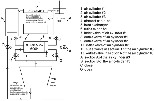
This is stage 3. Now the air cylinder #2 is filled with air whose temperature is 600 K and whose pressure is 0.202 MPa, the section B of the air cylinder #3 is filled with air whose temperature is 300 K and whose pressure is 0.202 MPa, the piston of the air cylinder #2 and that of the air cylinder #3 will be in a fixed position; the piston of the air cylinder #1 is at the bottom of air cylinder #1, and the piston of the air cylinder #3 is at the far right side of the air cylinder #3, there is no air remaining in the air cylinder #1 and the section A of the air cylinder #3; all valves will close. The section B of the air cylinder #3 will extract heat from the air cylinder #2 by means of the heat exchanger, as shown in Figure .
In Figures and , b → c indicate that the air stays in the air cylinder #2 which is an isochoric exothermic process.
After the isochoric exothermic process, the temperature of the air cylinder #2 is Tc, Td = Tc = 300 K, the inside pressure of the air cylinder #2 is Pc, Pc = 0.101 MPa.
In Figures and , d → a depict that the air stays in the section B of the air cylinder #3. This is an isochoric endothermic process, where the section B of the air cylinder #3 extracts heat from the air cylinder #2 through the heat exchanger.
After the isochoric endothermic process, the temperature of the section B of the air cylinder #3 is Ta, Ta = 600 K, the section B of the air cylinder #3’s pressure is 0.404 MPa.
This is stage 4. Now the air cylinder #2 is filled with air whose temperature is 300 K and whose pressure is 0.101 MPa, the section B of the air cylinder #3 is filled with air whose temperature is 600 K and the pressure is 0.404 MPa, the pistons of the air cylinder #2 and the air cylinder #3 will still be in fixed positions: one piston is at the bottom of air cylinder #1, and the other piston is at the far right side of the air cylinder #3. There is no air remaining in the air cylinder #1 and in the section A of the air cylinder #3. The outlet valve in section B of the air cylinder #3 is open, the inlet valve of the air cylinder #1 is also open, and the other valves are now closed, as shown in Figure .
The air will flow through the turbo expander; it is an isothermal endothermic expansion process.
When the air leaves the turbo expander it enters the air cylinder #1.
Due to the outlet valve in section B of the air cylinder #3 being now open and connected to the inlet of the turbo expander, the pressure in section B of the air cylinder #3 will drop, and when its pressure is the same as that of the airproof container, Pd = Pcontainer = 0.202 MPa, the pistons of the air cylinder #2 and the air cylinder #3 will not be in a fixed position.
In Figures and , c → d show that the air stays in the air cylinder #2, which is an isothermal exothermic compression process. At the beginning, because the inside pressure of the air cylinder #2 is lower than that of the airproof container, 0.101 MPa = Pc < Pcontainer = 0.202 MPa, the atmospheric pressure of the airproof container pushes the piston forward, and this compresses the air; consequently, the inside pressure in the air cylinder #2 rises until it is equal to that of the airproof container, Pd = Pcontainer = Pb. Consequently, the outlet valve opens and the piston pushes on towards the bottom of the air cylinder #2, and the air then exits cylinder #2, and the air then exits cylinder #2, and enters the section A of the air cylinder #3.
The inertia of the airflow, will mean that the piston of the air cylinder #3, also, will be pushed towards the far left side of the air cylinder #3, and the air then exits the section B of the cylinder #3 and enters the turbo expander.
The above loops form the working cycle.
Let us suppose that the air is the ideal gas; the adiabatic exponent of the air is k, where k = 1.4.
To depict the cycle clearly and simplify the calculation, let us suppose the temperature of the heat source is Ta, which is also the temperature of the turbo expander’s inlet and outlet, where:(1)
The pressure of the turbo expander’s inlet is(2)
Due to the structure of the turbo expander, the pressure of its outlet can be controlled. The pressure of the turbo expander’s outlet is(3)
a → b depicts that the air flow through the turbo expander, which is an isothermal endothermic expansion process,
The work of the isothermal endothermic expansion process a → b is Wa→b, which can be obtained as follows:(4)
where R is the gas constant of the air, R = 287 J (kg K)−1.
The heat of the isothermal endothermic expansion process a → b is Qa→b, which can be obtained as follows:(5)
Let us suppose the temperature of the environment is Tc, which is given by:(6)
b → c depicts that the air stay in the air cylinder #1, and in air cylinder #2, which is an isochoric exothermic process:(7)
(8)
The work of the isochoric exothermic process b → c is Wb→c, which is given by:(9)
The heat of the isochoric exothermic process b → c is Qb→c, which can be obtained as follows:(10)
The work of the isothermal exothermic compression process c → d is Wc→d, the atmospheric pressure of the airproof container Pcontainer works on both the piston and the air, for the air, Wc→d is a negative work,(11)
(12)
The heat of the isothermal exothermic compression process c → d is Qc→d, which is given by:(13)
The work of the isochoric endothermic process d → a is Wd→a, which is given by:(14)
The heat of the isochoric endothermic process d → a is Qd→a,(15)
(16)
Qb→c and Qd→a are the internal heat exchange through the heat exchanger.
The total heat generated during the cycle is Q, which absorbs the heat:(17)
The total work of the cycle is W, which is given by:(18)
(19)
During the isothermal exothermic compression process c → d, because the inside pressure of the air cylinder #1 is Pc, Pc = 0.101 MPa, the atmospheric pressure of the airproof container is Pcontainer, where Pcontainer = 0.202 MPa, Pc < Pcontainer, where the atmospheric pressure of the airproof container causes the piston to move and compress the low-pressure air, and the inside pressure of the air cylinder #1 rises until it is equal to the atmospheric pressure of the airproof container. The new type of Stirling heat engine does not need any additional fuel to compress the air; the atmospheric pressure performs the work on the piston and the displacement of the piston is increased during the isothermal exothermic compression process c → d, as the inside pressure of the air cylinder #1 drops below the atmospheric pressure of the airproof container; the work that the atmospheric pressure of the airproof container does on the piston is Wp, which is a positive work and is numerically equal to Wc→d. This work can be utilized by this new type of Stirling heat engine:(20)
As Wp is a positive work, therefore, the actual work that the new type of engine produces is WA, where(21)
The thermal efficiency of the new engine is η, which can be obtained as follows:(22)
The summary results are presented in Table .
Table 1. Summary results.
3. Discussion
From the Equation (22), one can know that the thermal efficiency η is greater than 100% theoretically, some readers may think that the new engine is a perpetual motion machine and so may ask the question: “What is the external energy source?” The following statements should therefore provide the answer:
First, according to Equations (17)–(19), the new type of Stirling heat engine does not violate the first law of thermodynamics; therefore, it is not the first perpetual motion engine.
Second, it does not violate the second law of thermodynamics.
In fact, the new type of heat engine has both a hot reservoir and a cold reservoir.
During the isothermal endothermic expansion process a → b, the heat source is a hot reservoir.
During the isothermal exothermic compression process c → d, the environment is the cold reservoir.
The atmospheric pressure of the airproof container can be utilized as the external energy source, the isothermal exothermic compression process c → d does not need to consume the work of the isothermal endothermic expansion process a → b, and the work of the isothermal exothermic compression process c → d can be utilized by the new engine. Therefore, the new type of heat engine’s thermal efficiency is greater than 100% theoretically.
In fact, a new type of refrigerator which can utilize the atmospheric pressure and can, in theory, produce a net electrical energy, has already been published in International Journal of Sustainable Engineering (Gong Citation2014).
4. Conclusion
The new engine does not need the work of isothermal endothermic expansion process to compress the working fluid during isothermal exothermic compression; it means that the new type of Stirling heat engine does not need more fuel to produce net work, and its thermal efficiency is higher than existing sterling engines.
The atmospheric pressure of the airproof container can be utilized as the external energy sources for the new type of Stirling heat engine; the work that the atmospheric pressure of the airproof container does on the piston is positive; it means that the new engine’s thermal efficiency should be greater than 100% theoretically.
Future work of an experimental nature is needed to evaluate the practicality of the new type engine described above.
| Nomenclature | ||
| atm | = | standard atmospheric pressure |
| k | = | adiabatic exponent of the air (k = 1.4) |
| Pa | = | pressure of the turbo expander’s inlet (atm) |
| Pcontainer | = | atmospheric pressure of the airproof container, it is equal to that of the outlet of the turbo expander |
| Pd | = | pressure which is after the isothermal exothermic compression process c → d (atm) |
| Qa→b | = | heat of the isothermal endothermic expansion process a → b (kJ kg−1) |
| Qc→d | = | heat of the isothermal exothermic compression process c → d (kJ kg−1) |
| R | = | gas constant of the air (R = 287 J (kg K)−1) |
| T | = | temperature (K) |
| Tb | = | temperature of the turbo expander’s outlet and of the heat reservoir (K) |
| Td | = | temperature of the environment (K) |
| WA | = | actual work that the new type of Stirling heat engine produces (kJ kg−1) |
| Wb→c | = | work of the isochoric exothermic process b → c (kJ kg−1) |
| Wd→a | = | work of the isochoric endothermic process d → a (kJ kg−1) |
| E | = | energy (kJ kg−1) |
| P | = | pressure (atm) |
| Pb | = | pressure of the turbo expander’s outlet (atm) |
| Pc | = | pressure which is after the isochoric exothermic process b → c (atm) |
| Q | = | total heat generated during the cycle (kJ kg−1) |
| Qb→c | = | heat of the isochoric exothermic process b → c (kJ kg−1) |
| Qd→a | = | heat of the isochoric endothermic process d → a (kJ kg−1) |
| S | = | entropy (J k−1) |
| Ta | = | temperature of the turbo expander’s inlet and of the heat reservoir (K) |
| Tc | = | temperature which is after the isochoric exothermic process b → c and temperature of the environment (K) |
| W | = | total work of the cycle (kJ kg−1) |
| Wa→b | = | work of the isothermal endothermic expansion process a → b (kJ kg−1) |
| Wc→d | = | work of the isothermal exothermic compression process c → d (kJ kg−1) |
| Wp | = | work that the atmospheric pressure of the airproof container does on the piston (kJ kg−1) |
Disclosure statement
No potential conflict of interest was reported by the author.
Acknowledgements
The author thanks Dr Dorothy Middleton of Durham University for her help in preparing the manuscript, and Ms Huilan Shu, Ms Fengjuan Xu and Mr Lihua Ma for their assistance.
References
- Butterman, E. n.d. Thomas Newcomen. ASME. https://www.asme.org/engineering-topics/articles/history-of-mechanicalengineering/thomas-newcomen.
- Gong, Bing Xin. 2014. “A New Type of Refrigerator and its Cycle.” International Journal of Sustainable Engineering 7 (3): 194–199. doi:10.1080/19397038.2013.848953.
- Lira, C. T. n.d. Brief History of the Steam Engine. Michigan State University. http://www.egr.msu.edu/~lira/supp/steam/index.htm.
- Martini, W. R. 1983. Stirling Engine Design Manual, 4–6. 2nd ed. Washington, DC: NASA.
- Walker, G. 1980. Stirling Engines. New York, NY: Oxford University Press, 19.

