
Abstract
The behaviour of a decentralized polygeneration plant providing synthetic natural gas (SNG), steam and electrical power is simulated in three scenarios in this study. The plant size is based on an assumed capacity of decentralized polygeneration plants processing 1070 m3 h−1 (STP) of syngas. 396 m3 h−1 (STP) of raw SNG, 0.4 t h−1 of steam at 5 bar and 670 kW of electrical power can be generated by the plant at the reference scenario. Methanation reactor and steam generator are modelled in detail. Further results indicate that such a polygeneration plant can provide positive and negative operation reserves for the electricity network to the extent of 100% of the reference power output, while the amount of generated steam varies by less than 40%. At the same time, the generated SNG quality keeps constant. Lower variations in the amount of generated steam are applicable when reducing the operation reserve capacity.
1. Introduction
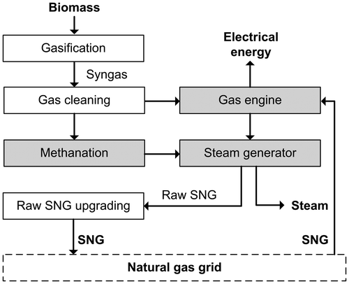
A sufficient energy supply is a prerequisite of modern economies in particular and of human well-being in general while accounting for substantial CO2 emissions (Asif and Muneer Citation2007). A sustainable development (Giddings, Hopwood, and O’Brien Citation2002) of the energy system is mandatory to guarantee biodiversity and human well-being at the same time. In order to reduce CO2 emissions renewable energy sources have to be implemented into the energy system (Ragauskas et al. Citation2006; Rönsch, Zeymer, and Majer Citation2014). The use of biomass provides one way to meet this target as was shown in (Rönsch, Zeymer, and Majer Citation2014) by calculating greenhouse gas mitigation costs for synthetic natural gas (SNG) and methanol. In this context, gasification represents a key technology that allows the use of a wide range of biomass feedstocks to produce valuable gas mixtures (Dornburg and Faaij Citation2001; Wahlund, Yan, and Westermark Citation2004). A downstream synthesis unit can convert these gas mixtures into fuels (e.g. methane and Fischer-Tropsch diesel) or basic chemicals (e.g. methanol) for the pharmaceutical and chemical industry. Alternatively, the gas can be utilized in engines or turbines for the generation of electrical power (Figure ).
Figure 1. Polygeneration of SNG, steam and electrical power by biomass gasification.
The combination of gasification and synthesis units in a polygeneration plant can provide heat, electrical power and fuels from the primary gas in different shares – ideally demand-actuated. In times of a low electrical power demand, a high fraction of fuels can be produced and in times of a high electrical power demand a low amount of fuels can be synthesised. However, this flexible plant operation is related to particular operation requirements of the synthesis process (Iglesias González, Eilers, and Schaub Citation2016).
The generation of SNG from synthesis gas (syngas) is an attractive conversion route in a polygeneration plant since both a useful and well-storable fuel and heat are the products thereof (Rönsch, Schneider, et al. Citation2016). Furthermore, a polygeneration plant could provide major positive and negative operating reserves in electricity networks by adjusting the flow rate of syngas (SG) transferred to the subsequent components gas engine and methanation reactor. Therein, the SG source (gasifier) could be operated at constant conditions avoiding changes in the SG composition that might result from varying operation conditions. This concept is further discussed in Section 3.
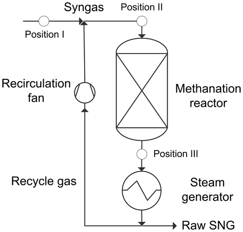
In order to demonstrate the performance of a polygeneration plant that offers operating reserves for the electricity network, the dynamic behaviour of a methanation reactor with gas recirculation for cooling (Figure ) and a gas engine are simulated. Both components are connected to steam generators whose behaviours are dynamically simulated as well. The power consumption of the recirculation fan (Figure ) is also considered. The analysis is based on process modelling and simulation of the methanation reactor and the steam generator. The simulation scenarios are discussed in Section 3.
Figure 2. Fixed-bed methanation reactor with gas recirculation for cooling and steam generator. Data is compared in Table at the three marked positions.
2. Model development
The model consists of submodels for a fixed-bed methanation reactor (represented by a continuously stirred tank reactor) and a steam generator. In addition, a database for the estimation of physical properties is incorporated which is described together with programming aspects for the two submodels in the Supplementary data.
The gas species CO2, CO, H2O, H2, CH4 and N2 are considered in the simulation. Methanation reactor and steam generator are modelled with a 10 cm thick insulation (I) made of mineral fibres and its typical properties (cp,I = 600 J (kg K)−1, λI = 42 mW (m K)−1, ρI = 20 kg m−3) (Al-Homoud Citation2005; Papadopoulos Citation2005). Air (A) at a fixed temperature of 25 °C is assumed as environment of any insulation. In the following, the submodel of a methanation reactor is described in Section 2.1, prior to a characterization of the steam generator submodel in Section 2.2.
2.1. Methanation reactor
2.1.1. Basic model description
A continuously stirred tank reactor model is applied in order to predict the behaviour of a fixed-bed methanation reactor. It comprises the four phases SG, catalyst bed (CB), reactor case (RC) and reactor insulation (RI). The specifications of the methanation reactor (2 m length, 0.32 m3 catalyst volume) are based on data of the ADAM I methanation pilot plant (Harms, Höhlein, and Skov Citation1980). Only the first reactor with gas recirculation for reactor cooling of the ADAM I pilot plant is considered in this work (Figure ). The recirculation ratio is defined as the ratio of flow rates of recirculation and feeding and was kept constant at 1.65 since experimental data are available for this condition (Harms, Höhlein, and Skov Citation1980).
As described in (Harms, Höhlein, and Skov Citation1980), the reaction zone in the CB is shorter than 20 cm, the radial gradient at a maximum bed temperature of 600 °C is smaller than 10 K and the gas composition is equal to the equilibrium composition at the reactor exit temperature. Due to these statements, it is assumed that the methanation reactor can be modelled by a continuously stirred tank reactor and an exit gas composition based on the chemical equilibrium without causing major deviations. The chemical equilibrium calculations are conducted on the basis of equilibrium constants for the methanation and the water–gas shift reaction which are taken from (Hiller Citation2002). The accuracy of the simulated parameters in regard to the experimentally determined parameters is discussed in Section 4.
In Harms, Höhlein, and Skov (Citation1980), the reported pressure drop along one methanation reactor amounted to about 0.1 bar at an inlet pressure of 27.2 bar. Due to this, no pressure drop is considered in this submodel. Simulations are carried out at an inlet pressure of 27.1 bar and compared to experimental results of the ADAM I pilot plant in order to demonstrate the accuracy of the model. The results are presented in Section 4.
2.1.2. Set of differential equations
In the following, the set of energy balances for every phase (SG, CB, RC and RI) of the methanation reactor is described. All types of thermal power considered in this paper (heat convection, heat conduction and reaction heat) are described in Table . The energy balance of the CB includes the thermal power released from chemical reactions (methanation and water-gas shift) Pchem and the power transferred to the gas PCB_SG (Equation (1)).(1)
Table 1. Description of the considered types of thermal power and the procedure for their calculation.
The energy balance of the SG consists of the thermal power released from the CB, the power transferred to the RC and the power necessary to heat the SG from the inlet temperature TSG,in to the outlet temperature TSG,out (Equation (2)).(2)
Equation (3) represents the energy balance of the RC which comprises the difference between the heating power originating from the SG and the power conducted to the insulation (RI). The temperature TRC_RI is defined at the intersection between case and insulation in such a way that a steady thermal flux in both phases is guaranteed (compare Table ).(3)
Finally, the energy balance of the insulation (Equation (4)) consists of the difference in the heating power being conducted from the RC and being transferred to the environment (A).(4)
2.2. Steam generator
2.2.1. Basic model description
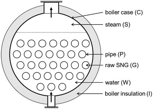
A boiler with horizontally oriented, cylindrical pipes for heat exchange is modelled for steam generation. A cross-sectional view of the boiler is displayed in Figure . This steam generator submodel includes the phases hot gas (G), heat-exchanger pipes (P), liquid water (W), steam (S), boiler case (C) and boiler insulation (I). Heat exchange between the hot raw SNG coming from the methanation reactor and the liquid water in the boiler is conducted by 50 cylindrical one-pass gas pipes. The phrase ‘one-pass gas pipes’ means that the hot gas passes only once through the boiler. There is no change in the direction of the gas. One of the nP gas pipes is discretized one-dimensionally by 22 nodes which include the in- and outlet as the first and last node. The other 20 nodes are equidistantly centred in each control volume. It is assumed that all pipes behave in the same way and are considered as identical.
Figure 3. Cross-section through the steam generator naming the modelled phases. The number of pipes in this sketch is lower than in the model.
All other phases are modelled zero-dimensionally and represent ideally mixed phases. The parameters describing the modelled steam generator are summarised in Table . The volumes of liquid water and steam inside of the boiler are considered as constant which is practically realised by fast-acting level sensors, pumps and valves. The influence of gravity is generally neglected. Pressure drop calculations are described in the Supplementary data.
Table 2. Parameters describing the modelled steam generators.
The steam generator model was validated by comparison with the predictions of the commercial software ‘PowerPlantSimulator’ by KED which is an industrial standard tool (KED Citation2014). A satisfying conformity in the predictions of both simulations was found.
2.2.2. Set of differential equations
The hot gas (G) is controlled by an energy balance (Equation (5)) and a momentum balance (Equation (6)) at every computational node e. Equation (5) includes terms for the energy loss due to a pressure drop and heat transfer to the pipes (PG_P). Equation (6) considers momentum variations due to a pressure drop but does not guarantee a constant mass flow alone. That is the reason for introducing a ‘disturbance term’. It is iteratively calculated by the requirement of a constant mass flow in every volume element of a pipe.(5)
(6)
The energy balance of the water phase (W) (Equation (7)) considers incoming and outgoing water flows (feeding water and evaporated water) as well as transferred heat. The latter includes the thermal power released from the pipes (PP_W) and the power transferred to the boiler case (PW_C). All thermal powers are calculated based on the formulations summarized in Table .(7)
The steam phase (S) is characterized by an energy balance (Equation (8)) and a mass balance (Equation (9)). Equation (8) considers newly evaporated water (steam input) and steam being released from the boiler (steam output), as well as the thermal power being transferred to the boiler case (PS_C). In Equation (9), only the incoming and outgoing steam flows contribute to the change in the phase’s density.(8)
(9)
A single energy balance for each remaining phase describes the changes in the temperature for the boiler pipe (P, Equation (10)), the boiler case (C, Equation (11)) and the boiler insulation (I, Equation (12)). The power of conducted heat between boiler case and insulation (PC_I) is calculated as in the case of the methanation reactor (PRC_RI, Table ).(10)
(11)
(12)
2.3. Additional components
A gas engine (e.g. GE Jenbacher type 6) is imitated by assuming an exhaust gas temperature of 470 °C and a linear dependence of its electrical efficiency on the load. Electrical efficiencies of 38.8, 37.5 and 36.4% at loads of 100, 75 and 50%, respectively, are used as supporting points defining a linear dependence. The load-dependent efficiency is multiplied by the lower heating value of the raw SNG to approximate the power output of the gas engine. The exhaust gas solely consisting of CO2, H2O and N2 enters the steam generator with a temperature of 470 °C where most of its thermal energy is depleted.
The power consumption of a recirculation fan is assumed based on manufacturer data for a rotary screw compressor of the relevant performance category. Power consumptions of 37.87, 58.25, 79.09 and 101.56 kW at flow rates of 4.77, 8.69, 12.49 and 16.11 m3 min−1, respectively, define a third-order polynomial that is applied to estimate the power consumption of the recirculation fan.
The operation of a gas engine and a recirculation fan are partly simulated in this work at very low loads that might not be technically feasible. This is justified by the scope of this work to show what is theoretically possible. Practically, the maximal adjustment of the SG flow rate has to be based on the operational range of the applied components which might be lower than assumed here.
3. Simulation scenarios
A polygeneration plant could offer positive and negative operating reserves in electricity networks when being equipped with a methanation reactor and a gas engine. Primary reserves have to adjust their output by at least 2% within 30 s and keep that level for 15 min (European Network of Transmission System Operators for Electricity Citation2014).
The SG source of a polygeneration plant offering primary operating reserves for the electricity network could provide e.g. 50% of the SG to the gas engine and 50% to the methanation reactor at standard operation (scenario ‘SNG and power’). The produced SNG is stored in the natural gas grid. Positive operating reserves can be provided when the SG input of the gas engine is increased (e.g. from 50 to 90% in scenario ‘power’). Negative operating reserves can be realized by decreasing the SG input of the gas engine (e.g. from 50 to 10% in scenario ‘SNG’). The SG flow rates are linearly adjusted within 30 s, kept constant at this level for 15 min and set back to the reference value within 30 s in dynamic simulations. The two last scenarios simulate one cycle where an operation reserve is offered. The input flow rates of methanation reactor, gas engine and recirculation fan for the three described scenarios are summarized in Table . The SG composition at position I in Table is applied in all simulations.
Table 3. Input flow rates for methanation reactor, gas engine and recirculation fan as well as the power output of the gas engine and the power consumption of the recirculation fan during the three scenarios.
Table 4. Reported and simulated conditions and compositions of the gases at positions I, II and III in Figure 2 of the methanation reactor at a pressure of about 27 bar, a recirculation ratio of 1.65 and steady-state.
It is assumed that decentralized methanation units will be operated at pressures between one and ten bar (Seemann et al. Citation2005). This is justified by a lower complexity and less investment costs compared to high pressure components. For simulations of a decentralized methanation unit, a pressure value of 5 bar is assumed. The steam generator is set to produce steam at 5 bar as well.
In the following Chapter 4, dynamic simulations of the methanation reactor at 27.1 and 5 bar are carried out at a starting temperature of 300 °C at every phase until the steady-state is reached. The temperatures and the concentrations of each gas species at steady-state are reported in the respective chapter. A gas pressure of 27.1 bar is applied in order to verify the methanation submodel. A gas pressure of 5 bar is used when analysing a decentralized polygeneration plant.
Note that the results of scenario ‘SNG’ are only realistic for methanation reactors with sufficiently long bed lengths which guarantee that the chemical equilibrium is reached at the outlet (Iglesias González, Eilers, and Schaub, Citation2016).
4. Results and discussion
The experimental parameters found in the ADAM I pilot plant (Harms, Höhlein, and Skov Citation1980) at the three positions marked in Figure are summarized in Table . The results of the methanation reactor submodel at those experimental conditions (27.1 bar) at steady-state are quoted in Table for comparison. The simulated temperature and the composition of the raw SNG show relative deviations below 0.4 and 3%, respectively, in regard to the experimental values found in the ADAM I pilot plant (Table ). The higher deviations in the raw SNG composition (up to 3%) indicate that the experimentally determined composition in (Harms, Höhlein, and Skov Citation1980) differs to this extent from the ideal composition based on the chemical equilibrium.
4.1. Scenario ‘SNG and Power’
The conditions of educt and product gas of the methanation reactor at positions II and III (Figure ) at a pressure of 5 bar and steady-state are displayed in Table and are indicated by the superscript ‘1’. The reduction of the methanation pressure from 27.1 to 5.0 bar results in a lower steady-state temperature due to a shift of the chemical equilibrium to the educts of the methanation reaction. The outlet concentrations of CH4 and H2 are reduced from 37.6 to 32.7 vol.-% and increased from 20.5 to 29.4 vol.-%, respectively. These results demonstrate the extent of the reduction of the CH4 yield when the methanation pressure is reduced to a relatively low value. The lower CH4 yield and national feed-in directives for the natural gas grid have to be regarded in the planning of decentralized methanation units.
396 m3 h−1 of raw SNG are produced by the polygeneration plant at steady-state. The gas engine provides an electrical power output of 670 kW (50% nominal load) while the recirculation fan consumes 39 kW (Table ). The raw SNG output of the methanation reactor and the exhaust gas output of the gas engine are cooled from 568 to 184 °C and from 470 to 190 °C in their respective steam generators (Table ). The exchanged power is sufficient to generate 0.4 t h−1 of steam at 5 bar.
Table 5. Temperatures of the raw SNG and the exhaust gas at in- and outlet of the two steam generators as well as the total flow rate of the generated steam at 5 bar during the three scenarios.
4.2. Scenario ‘SNG’
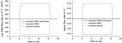
At t = 0 s, the polygeneration plant is at steady-state. In order to simulate the dynamic behaviour, the input flow rates of the methanation reactor and the gas engine are adjusted within 30 s to the values quoted in Table , kept at that level for 15 min and set back to the reference level within 30 s. This conforms to one cycle of the polygeneration plant offering negative operation reserves. The electrical power output of the gas engine (5% load) is reduced to 63 kW and the power consumption of the recirculation fan is raised to 61 kW. The temperatures of CB and RC in the methanation reactor are increased by only 0.4 and 0.6 K, respectively, not changing the chemical composition of the produced raw SNG. The resulting steam flow rate is reduced to 0.24 t h−1, while the raw SNG flow rate is increased to 753 m3 h−1 (STP) (Figure ). The outlet temperatures of raw SNG and exhaust gas at the steam generators are affected by up to 20 K relative to the reference scenario (compare Table ).
Figure 4. Mass-based flow rates of the raw SNG leaving the methanation reactor (left) and of the steam collectively produced by both steam generators (right) during the three scenarios.
4.3. Scenario ‘Power’
At t = 0 s, the polygeneration plant is at steady-state and the input flow rates are adjusted as quoted in Table . The polygeneration plant offers positive operation reserves in this scenario as the electrical power output is increased to 1353 kW (100% load). The power consumption of the recirculation fan is reduced to 17 kW. The temperatures of CB and RC in the methanation reactor are decreased by only 0.8 and 2.2 K, respectively. The chemical composition of the produced raw SNG is not affected. The flow rates of steam and raw SNG amount to 0.55 t h−1 and 40 m3 h−1 (Figure ), respectively. The temperatures of raw SNG and exhaust gas at the outlets of both steam generators are affected by up to 31 K relative to the reference scenario (compare Table ).
4.4. Discussion of the results
Simulations at a SG pressure of 5 bar show that the temperature of the raw SNG and the CB change by less than 1 K when the input flow rate of the methanation reactor is increased from 535 to 1017 m3 h−1 (STP) or reduced from 535 to 54 m3 h−1 (STP) for 15 min. Since the recirculation ratio is kept constant at 1.65, the recirculation flow rate is changed parallel to the input flow rate. At the same time, the RC temperature changes by less than 2 K. These results indicate that outlet temperature and composition of the raw SNG are not changed significantly when the methanation reactor is operated load-flexible for a short time interval like 15 min. The construction of polygeneration plants that participate in the market for operation reserves is encouraged by these results. Additional revenues can be generated by this concept in comparison to plants which do not participate in that market. Nevertheless, more expensive control systems and load-flexible components (recirculation fan and gas engine) are necessary.
The total electrical power output (power generated by the gas engine minus power consumed by the recirculation fan) of the described polygeneration plant is 631 kW at the reference scenario with a steam generation of 0.4 t h−1. In the ‘power’ scenario, the total power output increases to 1336 kW (increase of 112% or a positive operation reserve of 705 kW) with a steam generation of 0.55 t h−1 (increase of 38%). In the ‘SNG’ scenario, the total power output amounts to only 2 kW (decrease of nearly 100% or a negative operation reserve of 629 kW) with a steam generation of 0.24 t h−1 (decrease of 39%). These high operation reserves (nearly 100% of the reference output) are principally possible while the amount of generated steam varies by less than 40%. Lower variations in the amount of generated steam are realisable if the reference SG flow rates (50% of the total SG to methanation reactor and gas engine) are redefined and the load adjustments are minimized.
CB models with a spatial discretization in one dimension (or more dimensions) as well as real CBs show distinct temperature distributions in a methanation reactor. Such distributions are averaged by the model applied in this work. Especially at the front of a methanation reactor, the CB and the SG exhibit significantly higher temperature changes than the ones resulting from the current approach. But the outlet temperature of the raw SNG likely behaves as presented in this work since the rear parts of the methanation reactor react very slowly on changes occurring at the front and serve a heat reservoir. As long as no hot spots form that lead to catalyst deactivation by sintering and carbon deposition (Bartholomew Citation2001), the results of this work are valid. The formation of hot spots could be controlled in a methanation reactor with gas recirculation by adjusting the recirculation ratio at the same time as the flow rate. The recirculation ratio has to be increased shortly before or parallel with a rising flow rate in order to minimize the heating of the CB.
5. Conclusions and outlook
The results presented in Section 4 indicate that decentralized polygeneration plants being equipped with a methanation reactor and a gas engine can produce 396 m3 h−1 (STP) of raw SNG, 0.4 t h−1 of steam at 5 bar and 670 kW of electrical power when 1070 m3 h−1 (STP) of SG are divided equally. If the distribution among methanation reactor and gas engine is changed to 10:90 or 90:10
| • | positive and negative operation reserves for the electricity network, respectively, by up to 100% of the reference power output and | ||||
| • | steam for district heating or industry with variations in the flow rate of less than 40% | ||||
can be provided while keeping the SNG quality for a short time interval like 15 min.
Lower variations in the steam flow rate are realizable while keeping the operation reserve capability in electricity networks by redefining the reference flow rates (e.g. a SG input at the methanation reactor of 70% instead of 50%) and minimizing the load adjustments (e.g. a variation in the total SG flow of only 30% instead of 50%). In order to obtain operation reserve capabilities, the operation conditions of the SG source (gasifier) do not need to be changed. Any problems resulting from varied operation conditions can be avoided by this approach.
The recirculation ratio of the methanation reactor determines the outlet temperature of the raw SNG and, therefore, its composition. The submodel of the methanation reactor can be used to perform studies of the recirculation ratio in order to
| • | reduce temperature changes caused by the adaptation of the SG flow rate and | ||||
| • | protect the catalyst from deactivation by sintering and carbon deposition. | ||||
Such studies of the recirculation ratio are especially meaningful when CB models with spatial discretization and realistic methanation kinetics are applied (Rönsch, Köchermann, et al. Citation2016) so that local hot spots can be located and their formation effectively controlled.
Thermal losses at the plant can be reduced if the excess heat from the raw SNG and the gas engine’s exhaust gas is transferred in a shared steam generator rather than in one steam generator for each component. The described system configuration might be combined with other or additional synthesis units to generate alternative fuels and basic chemicals from SG while keeping its operation reserve capability. Nevertheless, economic considerations for a profitable operation of the outlined polygeneration plant have to be performed in order to determine the plant size and the necessary price for the provision of operation reserves.
Nomenclature
Table
Disclosure statement
No potential conflict of interest was reported by the authors.
Supplemental data
Supplemental data for this article can be accessed http://dx.doi.org/10.1080/19397038.2016.1182598
References
- Al-Homoud, Mohammad S. 2005. “Performance Characteristics and Practical Applications of Common Building Thermal Insulation Materials.” Building and Environment 40: 353–366. doi:10.1016/j.buildenv.2004.05.013.
- Asif, M., and T. Muneer. 2007. “Energy Supply, its Demand and Security Issues for Developed and Emerging Economies.” Renewable & Sustainable Energy Reviews 11: 1388–1413.
- Bartholomew, C. H. 2001. “Mechanisms of catalyst deactivation.” Applied Catalysis A: General 212: 17–60.10.1016/S0926-860X(00)00843-7
- Dornburg, Veronika, and André P. C. Faaij. 2001. “Efficiency and Economy of Wood-Fired Biomass Energy Systems in Relation to Scale Regarding Heat and Power Generation using Combustion and Gasification Technologies.” Biomass and Bioenergy 21: 91–108.10.1016/S0961-9534(01)00030-7
- European Network of Transmission System Operators for Electricity. 2014. “Continental Europe Operation Handbook.” www.entsoe.eu.
- Giddings, B., B. Hopwood, and G. O’Brien. 2002. “Environment, Economy and Society: Fitting them Together into Sustainable Development.” Sustainable Development 10: 187–196.10.1002/(ISSN)1099-1719
- Harms, H., B. Höhlein, and A. Skov. 1980. “Methanisierung kohlenmonoxidreicher Gase beim Energie-Transport [Methanation of Carbon Monoxide Rich Gases for the Transportation of Energy].” Chemie Ingenieur Technik 52: 504–515.10.1002/cite.330520605
- Hiller, H. 2002. “Gas Production.” In Ullmann’s Encyclopedia of Industrial Chemistry. Vol. 6, pp. 13–15. Weinheim: Wiley-VCH.
- Iglesias González, María, Hilko Eilers, and George Schaub. 2016. “Flexible Operation of Fixed-Bed Reactors for a Catalytic Fuel Synthesis—CO2 Hydrogenation as Example Reaction.” Energy Technology 4: 90–103. doi:10.1002/ente.201500259.
- KED (Kraftwerktechnik Entwicklung Dynamik). 2014. PowerPlantSimulator. www.ked.de.
- Papadopoulos, A. M. 2005. “State of the Art in Thermal Insulation Materials and Aims for Future Developments.” Energy and Buildings 37: 77–86. doi:10.1016/j.enbuild.2004.05.006.
- Ragauskas, Arthur J., Charlotte K. Williams, Brian H. Davison, George Britovsek, John Cairney, Charles A. Eckert, William J. Frederick Jr., et al. 2006. “The Path Forward for Biofuels and Biomaterials.” Science 311 (5760): 484–489. doi:10.1126/science.1114736.
- Rönsch, Stefan, Jakob Köchermann, Jens Schneider, and Steffi Matthischke. 2016. “Global Reaction Kinetics of CO and CO2 Methanation for Dynamic Process Modeling.” Chemical Engineering & Technology 39 (2): 208–218. doi:10.1002/ceat.201500327.
- Rönsch, Stefan, Jens Schneider, Steffi Matthischke, Michael Schlüter, Manuel Götz, Jonathan Lefebvre, Praseeth Prabhakaran, and Siegfried Bajohr. 2016. “Review on Methanation – From Fundamentals to Current Projects.” Fuel 166: 276–296. doi:10.1016/j.fuel.2015.10.111.
- Rönsch, Stefan, Martin Zeymer, and Stefan Majer. 2014. “Treibhausgasvermeidungskosten von Synthetischem Methan und Methanol aus Biomasse und Braunkohle [Greenhouse Gas Mitigation Costs of Synthetic Methane and Methanol from Biomass and Coal].” Chemie Ingenieur Technik 86 (10): 1678–1689. doi:10.1002/cite.201400047.
- Seemann, M., S. Biollaz, S. Stucki, M. Schaub, C. Aichernig, R. Rauch, H. Hofbauer, and R. Koch. 2005. “Methanation of Biosyngas and Simultaneous Low-Temperature Reforming: First Results of Long Duration Tests at the FICFB Gasifier in Güssing.” 14th European Biomass Conference Biomass for Energy, Industry and Climate Protection – Proceedings, Paris. www.eee-info.net.
- Wahlund, Bertil, Jinyue Yan, and Mats Westermark. 2004. “Increasing Biomass Utilisation in Energy Systems: A Comparative Study of CO2 Reduction and Cost for Different Bioenergy Processing Options.” Biomass and Bioenergy 26: 531–544. doi:10.1016/j.biombioe.2003.09.003.