Abstract
Submerged-arc welding slag (SAWS) and rice husk (RH) wastes represent two particularly abundant metallurgical and agricultural wastes. This work focusses on the feasibility of SAWS, together with glass cullet and RHs, to develop lightweight porous glass–ceramics that could be useful for technical purposes. Effects of temperatures and amounts of RHs on the porosity and water absorption of porous glass–ceramics were discussed at various dosages of husks up to 20 wt%. Depending on the sintering temperature, XRD measurements confirmed the presence of more than two crystalline phases: diopside, jacobsite, MgAl2O4, Ca1.82Al3.64Si0.36O8 and pyrope. These samples exhibited magnetic properties which were related to the presence of jacobsite phase. Magnetization curve is a characteristic of soft ferromagnetic materials with magnetization saturating at ~0.82 emu/g. The present results show a promising way to treat submerged-arc welding slags, transforming it into useful porous and functional glass–ceramic products via a simple powder technology and sintering approach.
1. Introduction
Wastes, according to the Basel convention, are substances or objects which are disposed or are intended to be disposed or are required to be disposed of by the provisions of national laws (Baker et al. Citation2004). Wastes may be generated during the extraction of raw materials, the processing of raw materials into intermediate and final products, the consumption of final products and other human activities.
The increasing amount of metallurgical waste being produced as a result of rapid technological development, the simultaneous decrease in industrial dump areas, as well as the problems associated with environmental pollution are important issues demanding the attention of scientists and technologists. Slag, generated from the submerged-arc welding (SAW) process, represents one of the many types of wastes resulting from the industrial and metallurgical processes. SAW is a fusion welding method for producing tools and machine parts (e.g. carbon-manganese alloy, stainless steels, nickel based alloys) with required surface properties, particularly resistance to wear and corrosion. Submerged-arc welding slag (SAWS) is created during the submerged-arc welding of two pieces of steel (workpiece and the consumable electrode wire) in the presence of a welding flux. The primary function of the welding flux is to shield the arc and the molten weld metal from the harmful effects of the ambient atmosphere. During the welding process, a portion of flux melts and gets adhered to the solidified weld pool, leaving behind a hardened weld, a layer of hardened slag and un-melted granular flux. The granular and fusible flux is made up of lime, silica, alumina, MnO, MgO, TiO2, FeO, calcium fluoride and other mineral compounds (Bulter and Jackson Citation1967).
According to a feasibility study in 1996 by The Welding Institute (TWI), Lincoln Electric (LE) provides between 60,000 and 80,000 tonnes of SAW flux worldwide and approximately 36,000 tonnes in North America (Routley Citation2004). Currently, there is no established market or any specifications concerning the beneficial use of SAWS in any application. Although several solutions have been put forward for both the re-employment of the slag as an alternative to fresh flux for the same SAW operation (Beck and Jackson Citation1996; Datta, Bandyopadhyay, and Pal Citation2008; Sahni, Singh, and Pandey Citation2009; Singh and Pandey Citation2009) and safe disposal of such waste, novel and more effective waste management concepts are still to be developed in the framework of a global and integrated approach. Recycling of SAWS by applying modern technologies (powder technology and sintering route) represents an effective approach to safely use the discarded materials and produce application oriented products such as glass–ceramics (Chinnam et al. Citation2013; Colombo et al. Citation2003; Francis Citation2006; Francis, Rawlings, and Boccaccini Citation2002; Karamanov, Taglieri, and Pelino Citation1999; Ponsot et al. Citation2014; Rawlings, Wu, and Boccaccini Citation2006).
The application of powder technology to obtain high-quality products from oxide wastes (e.g. SiO2, Al2O3, CaO) is suitable for the production of a range of commercial materials including glass and glass–ceramics with specified porosities and enhanced physical and mechanical properties. Porous glass–ceramics can find application as filters, lightweight load-bearing structures, catalyst supports and membranes or components for thermal insulation or sound absorption (Ayadi et al. Citation2011; Chinnam et al. Citation2013; Fernandes, Tulyaganov, and Ferreira Citation2009; Ponsot and Bernardo Citation2013; Shutt, Campbell, and Abrahams Citation1972). In general, the welding industry generates huge amounts of slag, which needs an adequate methodology for its final treatment. Motivated by the concept of ‘waste to wealth’, Singh, Pandey, and Mani (Citation2006) reported that the addition of suitable alloying elements and deoxidizers to the submerged-arc welding slag would lead to its conversion into new flux called recycled flux. In Egypt, it is estimated that more than 5000 tonnes of flux was consumed annually. It has been estimated that one kg of flux is consumed for every kg of weld metal deposited. Such a large quantity of flux becomes slag waste and has to be disposed. However, to the authors’ knowledge, the suitability of the slag for the manufacture of functional glass–ceramics by the conventional sintering route has not been studied before.
A well-established and supported waste management policy should consider political, socio-economic, institutional and cultural factors as well as environmental and health aspects (Chinnam et al. Citation2013; Martuzzi, Mitis, and Forastiere Citation2010; Peter Citation1996). SAWS is potentially a valuable source of major oxides, e.g. CaO, SiO2, MnO, Al2O3 and Fe2O3, which are found in glass and ceramic products. Since the employed slag contains an average level of Fe2O3, one added motivation for the present work was to investigate the feasibility of developing magnetic glass–ceramics by the formation of appropriate iron-rich compounds. The beneficial use of SAWS in engineering applications reduces not only the mass of material that must be sent to a landfill but also is an important step in moving towards a more sustainable society.
2. Materials and methods
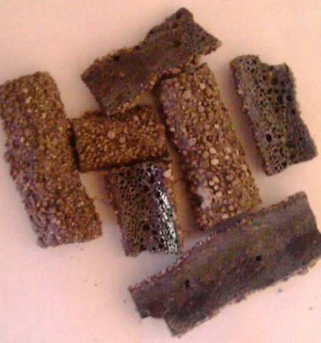
The processing of SAWS involves crushing and milling to a suitable powder form. Figure shows the aspect of slag generated during the submerged-arc welding (SAW) process. The chemical composition (weight %) of the investigated SAWS is shown in Table . The composition was determined by X-ray fluorescence analysis (PANalytical – AXIOS advanced). The relatively high content of manganese and iron oxides indicates the potential of this slag to develop magnetic phases upon appropriate treatment.
Table 1. Chemical composition of the investigated SAWS (wt%).
Rice husk (RH) is an agricultural waste material produced as a by-product during rice milling process. It contains about 75% organic volatile matter and the rest is converted into ash during the firing process. The RH contains around 85–90% amorphous silica. After preliminary tests, the processing temperature for rice husk-containing compositions was determined in the range of 900–1000 °C. Glass cullet and RHs were added and mixed with the SAWS powder. The batch sample containing 60% glass cullet and 40% SAWS was uniaxially compacted with RHs (1–20 wt%). The variation in properties of the resulting materials has been investigated with the following parameters: temperature (900–1000 °C), and RH percentage. The sintered samples were characterized by X-ray powder diffraction (D8 Brucker, Germany) with Ni-filtered CuKα radiation (λ = 1.54056 A°) and scanning electron microscope coupled with an EDX spectrometer (SEM-Jeol, JSM 5410). The X-ray diffraction patterns were matched to JCPDS data files (Bruker Advanced X-ray Solutions – DIFFRACplus evaluation package release 2001-EVA) to identify the crystalline phases. Porous glass–ceramics with various amounts of RHs were characterized in terms of porosity, water absorption and magnetic property.
| (1) | The Archimedes method was employed to measure water absorption after the sintered products had been placed in boiling water for 3 h. The water absorption was calculated as follows: Water absorption = (WS – WD/WD) × 100, where WD is the dry weight of the calcined foams, WS is the 3 h saturated surface-dry weight. | ||||
| (2) | Porosity is calculated from the bulk density and powder density using the following equation. Percentage of porosity = (1 – bulk density/powder density) × 100. The magnetic properties of selected samples were determined using a vibrating sample magnetometer (VSM–Model 9600)) at room temperature with a field of up to 20000 Gauss parallel to the vibration direction. The magnetization value was normalized by the sample weight, using the magnetic moment per gram (emu/g) as magnetization unit. The data were fit with a 3D option using SigmaPlot version 11, from Systat Software, Inc., San Jose, California, USA. | ||||
3. Results and discussion
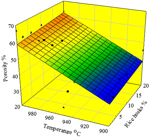
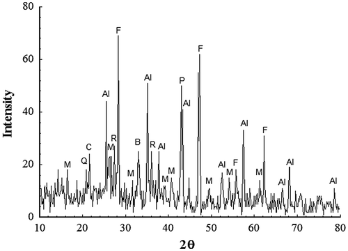
The main mineralogical phases of SAWS, determined by XRD, as seen in Figure are periclase (PDF 45-0946), Al2O3 (PDF 75-1865), mullite (PDF 82-0037), cristobalite (PDF 76-0934), fluorite CaF2 (PDF 77-2245), quartz (PDF 05-0490), braunite (Mn2O3)3MnSiO3 (PDF 74-1206) and rutile (PDF 87-0920). However, the major peaks correspond mainly to Al2O3, periclase, CaF2 and mullite. The effect of temperature (900–1000 °C) and amounts of RH (1–20%) on the physical property of porous glass–ceramics after sintering for a constant time period (60 min) were illustrated in Figure and . The sintering temperature at 900–950 °C showed a gradual increase in porosity up to ~ 40% with increasing amount of RHs (Figure ). On the contrary, samples sintered at higher temperatures 975–1000 °C showed insignificant variation in the porosity percentage using 1–3% RH. It is worth mentioning that the porosity was almost constant at higher amounts of RH. This may be due to the closure of pores resulting from the fusion of silica generated from RH and glass cullet. The porosity values were in the range of 63–55% and 66.76–63.5% at 975 and 1000 °C, respectively.
Figure 2. XRD of the as-received slag welding flux. CaF2 (F); Mullite (M); Rutile (R); Al2O3 (Al); (Mn2O3)3MnSiO3 (B); Periclase (P); Quartz (Q); Cristobalite (C).
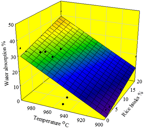
A diversion in the percentage of water absorption of specimens at lower and higher temperature can be observed at 900–950 °C, where the water absorption increases regularly and slightly till reaching a maximum at 20% RH (Figure ). However, the percentage of water absorption at higher temperature started at 34%, and increased slightly till achieving a maximum of ~42% at 1000 °C using 20% RH. This is caused mainly by open-pore closure, resulting in better densification of the porous glass–ceramics due to viscous flow of the compacted glass powder (Clark and Reed Citation1986; Francis Citation2006; Gutzow et al. Citation1998). This result is consistent with the XRD results and the occurrence of partial melting at 1000 °C.
We use Sigma plot to perform regression and curve fitting. The coefficient of determination R2 is a measure of how well the regression model describes the data. In spite of the relatively higher value of the coefficient of determination R2 for the 3D paraboloid model (second-order equation), the simplified 3D plane model fits and describes better the data. The coefficient of determination R2 was found equal to 0.5705 and 0.7719 for porosity and water absorption of the glass–ceramics, respectively.
A 3D plane equation was developed to correlate the value of porosity (P) and water absorption (WA) as a function of processing temperatures and amounts of RH. The evaluation is undertaken for 5% confidence level of significance.
(x = RH% and y = temperature).
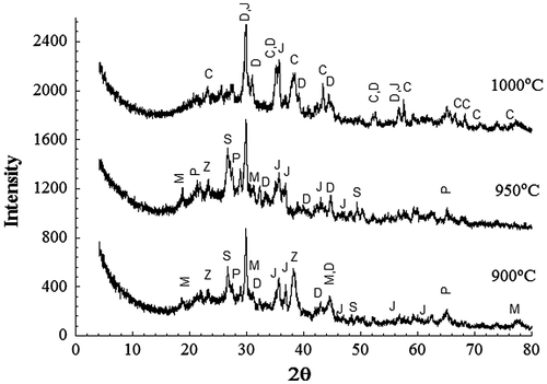
Figure represents the XRD patterns of sintered samples at different temperatures 900–1000 °C for 1 h with incorporation of 1% RH. It can be observed that the main crystalline phases at 900 and 950 °C are diopside Ca(Mg,Al)(Si,Al)2O6 (PDF 041-1370), jacobsite MgO(Mn,Fe)O.2Fe2O3 (PDF 002-1034), silica (PDF 05-0490) and magnesium dialuminium oxide (MgAl2O4, PDF 01-082-2424). However, other phases were also formed at low temperature 900 °C, belonging to calcium aluminium silicate (Ca1.82Al3.64Si0.36O8, PDF 026-0559), and pyrope [Mg3Fe2(SiO4)3](PDF 01-079-1662). The situation is different at higher temperature 1000 °C, where the following three phases were just detected: diopside CaMg(SiO3)2(PDF 011-0654), jacobsite MgO(Mn,Fe)O.2Fe2O3 and corundum Al2O3 (PDF 01-070-5679). At this high temperature, it can be suggested that the powders are densified by viscous flow sintering mechanism.
Figure 5. XRD patterns of powder samples of 1% RH sintered for 1 h at the indicated temperatures. D–diopside; J-jacobsite; C-corundum; M-MgAl2O4; P-pyrope; S-SiO2 Z-Ca1.82 Al3.64 Si0.36O8.
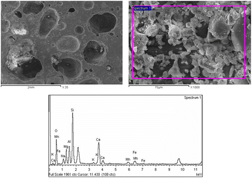
The XRD pattern of sintered samples at 1000 °C with incorporation of 20% RH showed the presence of diopside CaMg(SiO3)2 (PDF 011-0654) and jacobsite (MgO(Mn,Fe)O.2Fe2O3 (PDF002-1034) (Figure ). These crystalline phases, besides silica (SiO2) and magnesium dialuminium oxide (MgAl2O4), were also detected in the sintered sample at 900 °C for 1 h. It should be pointed out that the porous glass–ceramic under consideration is a complex system where the crystalline phases are not of simple stoichiometry; a more complicated reaction might occur that could lead to change in composition with temperature and amount of RH. At the highest temperature 1000 °C, partial melting occurred and the resulting material was consisted of diopside, jacobsite and a glassy SiO2 phase. Images aspects of porous glass–ceramic structures revealed the role of temperatures and amounts of RH on the extent of pore diameter and densification degree in particular at higher temperatures (975 and 1000 °C), where a more coherent and solid structure can be observed in Figure . An effective coarsening of the structure of porous glass–ceramics with increasing temperature is observed.
Figure 6. XRD patterns from powder samples of 20% RH sintered for 1 h at the indicated temperatures. D–diopside; J-jacobsite; C-corundum; M-MgAl2O4.
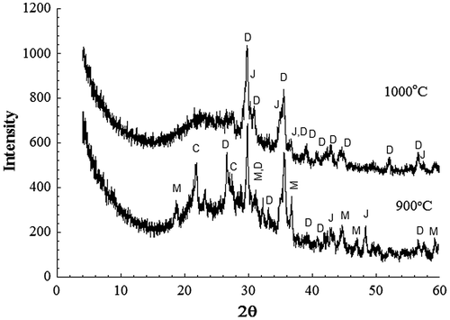
Figure 7. Image aspects of the porous glass–ceramic structures containing 20% RHs and sintered at various temperatures (a) 900 °C, (b) 975 °C, (c) 1000 °C and (d) 1000 °C at 6% RH.

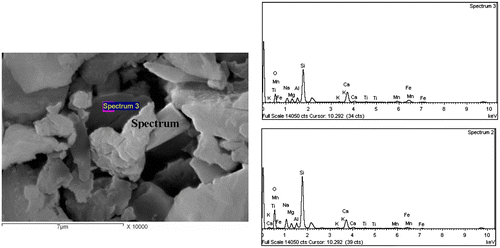
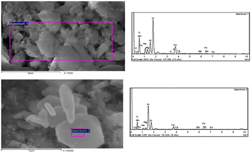
It should be noted that the relative content of RH and the processing temperatures affected the final properties of interest in this study, namely porosity, water absorption and magnetic property. Thus, a detailed microstructural investigation (SEM) was carried out on samples containing 1 wt% RH sintered at 900 and 1000 °C for 1 h (Figures and ). The samples have a well-developed glass–ceramic microstructure comprising a silicate matrix with dispersed crystalline phases, which appear dark and bright under SEM. The combination of EDAX and XRD analyses served to identify the crystalline phases. The bright particles and the dark grey particles in Figure were found to be enriched in metals, especially silicon, iron, aluminium, calcium, manganese and magnesium, and consequently they were assumed to be the diopside, jacobsite, cristobalite and MgAl2O4 phases that were detected by XRD. Table shows the quantitative elemental composition of the crystals. It is also interesting to note that the large bright grain in Figure was identified as being corundum and diopside crystals as it was found to be enriched mainly in aluminium followed by silica and small amounts of Ca, Mg, Mn and iron (Table ). The presence of Mn, Fe and Mg refers to the jacobsite phase. For the sake of comparison, the SEM images in Figure showed the influence of 20% RH on the microstructure development at 1000 °C and revealed the presence of significant porosity in accordance with the porosity data illustrated in Figure (see also Figure (c)).
Table 2. Quantitative elemental composition of the crystals in Figure 8.
Table 3. Quantitative elemental composition of the crystals in Figure 9.
From the study of Wu et al. (Citation2006), glass–ceramic foams have to be processed in the temperature range 1000–1050 °C. The apparent density of the foams produced from a mixture of coal-pond ash and bottle-glass cullet with the incorporation of 2 wt% SiC ranged from 0.2 to 0.4 g/cm3, and the porosity ranged from 70 to 90%. On the other hand, foams comprising 1 and 2 wt% carbonates showed significant variations with increasing temperature reaching the lowest apparent density (0.36–0.41 g/cm3) among the studied compositions after sintering at 850 °C. Further increasing the heat treatment temperature to 950 °C caused an increase in the apparent density (0.4–0.6 g/cm3) (Fernandes, Tulyaganov, and Ferreira Citation2009). Liao and Huang (Citation2012) have reported that the water absorption of glass foams produced from recycled water reservoir sediment with 15 wt% Na2CO3 addition calcined at 900 and 950 °C were 53.7% and 48.9%, respectively. The specific gravities of the foams were in the range of 0.81–1.34 g/cm3. However, the experimental results of the present study showed that magnetic porous glass–ceramics produced from a mixture of SAWS and glass cullet with the incorporation of RH as foaming agent have porosity values of 55–63%.
In general, the recycling of Fe-containing waste residues from industrial processes has shown potential to develop useful glass–ceramics for functional applications (Min'ko and Koval'chenko Citation2002; Romero-Perez et al. Citation2001). Three samples, sintered at 900 and 1000 °C for two different dosages of RH (20 and 1%), were measured and the magnetization curve for the one containing 20% RH and sintered at 1000 °C (specific magnetization M vs. field H) is presented in Figure . All curves are characteristic of soft ferromagnetic materials with magnetization saturating at 20000 G. There is no significant difference in the saturation magnetization and shape of the M–H loops; however, the sample sintered at 900 °C for 1 h (20% RH) exhibited larger specific coercivity and remanent magnetization values (0.755 emu/g and 159 G). The presence of this jacobsite phase MgO(Mn,Fe)O.2Fe2O3 made these samples magnetic, as assessed from the measurement of magnetic property. Mason (Citation1947) described jacobsite as an intermediate member of the magnetite-high hausmannite series based on experiments along the join Fe3O4–Mn3O4. It is well known that series of complex oxides exists between Mn3O4 and jacobsite (FeMn3O4) with varying magnetic properties. In our case, the structure and composition of the as-received slag and sintered products are complex and therefore, various crystalline phases and solid solutions between iron and other metallic oxides can be formed. There is no existing relation between the percentages of manganese and iron or both with the observed magnetic susceptibilities. But almost all the manganese samples exhibited ferromagnetism to some degree or other (Levy et al. Citation2015).
Figure 11. Magnetization curves of porous glass–ceramic containing 20% RH and sintered at 1000 °C for 1 h.
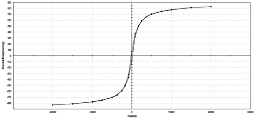
In a previous investigation (Francis Citation2007), the influence of temperature on the magnetic properties of glass–ceramics (GC) was investigated using blast furnace flue dust and blast furnace slag. It was found that the increase in processing temperature was seen to decrease the saturation magnetization and coercive force of the GC from 0.7 to 0.2emu/g and from 57.64 Oe to 36.3Oe, respectively. The decrease in the coercive force can be interpreted in terms of magnetic multi-domain structure formation. Since the hysteresis properties of a sample depend in large part on its purity and quality, one can engineer materials to optimize their properties for specific applications. It should be pointed out that the composition of SAW slag is more complex than that of steel slags and therefore, the formed crystalline phases are not of simple stoichiometry; a more complicated reaction might occur that could lead to tangible change in composition with time and temperature. Table reports the measured magnetic parameters of the porous glass–ceramics after heating at the above-mentioned temperatures. The minor changes in the magnetic properties of samples are attributed to the variation in the porosity with the applied temperature. This material might be used as a filler in composites absorbing high-frequency magnetic radiation and as tiles for heated floors of industrial premises (Min'ko and Koval'chenko Citation2002). It must be stated at this point that no mechanical data were recorded for this glass–ceramic composite, as this work is mainly focused to demonstrate the feasibility of using a mixture of SAW slag and waste glass together with RHs to produce a functional glass–ceramic material. We hope that this work will contribute to generate interests in the treatment of SAW slag. Besides further investigation of the magnetic properties and microstructure, more detailed characterization of the physical properties of the glass–ceramic produced, including mechanical properties is required for assessing the potential of these materials for a variety of industrial applications.
Table 4. Magnetic properties of the porous glass–ceramics. Ms, Mr and Hc are saturation magnetization, remanence and coercivity, respectively.
4. Conclusions
Submerged-arc welding slag (SAWS) is generated during the submerged-arc welding (SAW) process. The porous glass–ceramics made from mixtures of welding slag waste, glass cullet and 20 wt% RHs at 1000 °C exhibited a porosity of 67.76% and water adsorption of 42%. XRD measurements confirmed the presence of more than two crystalline phases: diopside, jacobsite, magnesium dialuminium oxide, aluminium silicate and pyrope. Magnetization curve of porous glass–ceramics using 20% RH is characteristic of soft ferromagnetic materials with magnetization saturating at ~0.82 emu/g. This work could bring industrial interests to adopt SWF as a source of waste, transforming it into porous and functional glass–ceramics for technical purposes.
Disclosure statement
No potential conflict of interest was reported by the authors.
References
- Ayadi, A., N. Stiti, K. Boumchedda, H. Rennai, and Y. Lerari. 2011. “Elaboration and Characterization of Porous Granules Based on Waste Glass.” Powder Technology 208: 423–426.10.1016/j.powtec.2010.08.038
- Baker, E., E. Bournay, A. Harayama, and P. Rekacewicz. 2004. “Vital Waste Graphics.” United Nations Environment Program and Grid-Arendal. http://www.grida.no/publications/vg/waste/page/2853.
- Beck, H. P., and A. R. Jackson. 1996. “Recycling SAW Slag Proves Reliable and Repeatable.” Welding Journal 75 (6): 51–54.
- Bulter, C. A., and C. E. Jackson. 1967. “Submerged Arc Welding Characteristics of CaO–TiO2–SiO2 System.” Welding Journal 46 (5): 445–448.
- Chinnam, R. K., A. A. Francis, J. Will, E. Bernardo, and A. R. Boccaccini. 2013. “Review: Functional Glasses and Glass–ceramics Derived from Iron Rich Waste and Combination of Industrial Residues.” Journal of Non-Crystalline Solids 365: 63–74.10.1016/j.jnoncrysol.2012.12.006
- Clark, T. J., and J. S. Reed. 1986. “Kinetic Processes Involved in the Sintering and Crystallisation of Glass Powders.” Journal of the American Ceramic Society 69: 837–846.10.1111/jace.1986.69.issue-11
- Colombo, P., G. Brusatin, E. Bernardo, and G. Scarinci. 2003. “Inertization and Reuse of Waste Materials by Vitrification and Fabrication of Glass-Based Products.” Current Opinion in Solid State and Materials Science 7 (3): 225–239.10.1016/j.cossms.2003.08.002
- Datta, S., A. Bandyopadhyay, and P. K. Pal. 2008. “Slag Recycling in Submerged Arc Welding and Its Influence on Weld Quality Leading to Parametric Optimization.” International Journal of Advanced Manufacturing Technology 39: 229–238.10.1007/s00170-007-1224-4
- Fernandes, H. R., D. U. Tulyaganov, and J. M. F. Ferreira. 2009. “Preparation and Characterization of Foams from Sheet Glass and Fly Ash Using Carbonates as Foaming Agents.” Ceramics International 35: 229–235.10.1016/j.ceramint.2007.10.019
- Francis, A. A., R. D. Rawlings, and A. R. Boccaccini. 2002. “Production of Glass–ceramics from Coal Ash and Waste Glass Mixtures.” Key Engineering Materials 206–213: 2049–2052.10.4028/www.scientific.net/KEM.206-213
- Francis, A. A. 2006. “Crystallization Kinetics of Magnetic Glass–Ceramics Prepared by the Processing of Waste Materials.” Materials Research Bulletin 41 (6): 1146–1154.10.1016/j.materresbull.2005.11.002
- Francis, A. A. 2007. “Magnetic Characteristics of Iron-Containing Glass Originated from the Mixture of Various Wastes.” Ceramics International 33: 163–168.10.1016/j.ceramint.2005.09.005
- Gutzow, I., R. Pascova, A. Karamanov, and J. Schmelzer. 1998. “The Kinetics of Surface Induced Sinter Crystallisation and the Formation of Glass–ceramic Materials.” Journal of Materials Science 33: 5265–5273.10.1023/A:1004400508154
- Karamanov, A., G. Taglieri, and M. Pelino. 1999. “Iron-rich Sintered Glass–ceramics from Industrial Wastes.” Journal of the American Ceramic Society 82: 3012–3016.
- Levy, D., L. Pastero, A. Hoser, and G. Viscovo. 2015. “Thermal Expansion and Cation Partitioning of MnFe2O4 (Jacobsite) from 1.6 to 1276 K Studied by Using Neutron Powder Diffraction.” Solid State Communications 201: 15–19.10.1016/j.ssc.2014.10.001
- Liao, Y. C., and C. Y. Huang. 2012. “Glass Foam from the Mixture of Reservoir Sediment and Na2CO3.” Ceramics International 38: 4415–4420.10.1016/j.ceramint.2012.01.080
- Martuzzi, M., F. Mitis, and F. Forastiere. 2010. “Inequalities, Inequities, Environmental Justice in Waste Management and Health.” The European Journal of Public Health 20 (1): 21–26.10.1093/eurpub/ckp216
- Mason, B. 1947. “Mineralogical Aspects of the System Fe3O4–Mn3O4–ZnFe2O4.” American Mineralogist 32: 426–511.
- Min'ko, N. I., and N. A. Koval'chenko. 2002. “Electrical and Magnetic Characteristics of Iron-containing Glass in Crystallization.” Glass and Ceramics 59 (9–10): 296–298.10.1023/A:1022053806492
- Peter, S. 1996. “Conceptual Framework for Municipal Solid Waste Management in Low-income Countries”, In UNDP/UNCHS (Habitat)/World Bank/SDC Collaborative Program on Municipal Solid Waste Management in Low-income Countries, Switzerland, SKAT (Swiss Centre for Development Cooperation in Technology and Management), Working Paper No. 9, August 1996.
- Ponsot, I., Y. Pontikes, G. Baldi, R. Chinnam, R. Detsch, A. Boccaccini, and E. Bernardo. 2014. “Magnetic Glass Ceramics by Sintering of Borosilicate Glass and Inorganic Waste.” Materials 7 (8): 5565–5580.10.3390/ma7085565
- Ponsot, I., and E. Bernardo. 2013. “Self Glazed Glass Ceramic Foams from Metallurgical Slag and Recycled Glass.” Journal of Cleaner Production 59: 245–250.10.1016/j.jclepro.2013.06.029
- Rawlings, R. D., J. P. Wu, and A. R. Boccaccini. 2006. “Glass–ceramics: Their Production from Wastes-A Review.” Journal of Materials Science 41 (3): 733–761.10.1007/s10853-006-6554-3
- Romero-Perez, M., J. Rincón, C. J. R. Oliver, C. D’Ovidio, D. Esparza, and D. Esparza. 2001. “Magnetic Properties of Glasses with High Iron Oxide Content.” Materials Research Bulletin 36: 1513–1520.10.1016/S0025-5408(01)00630-4
- Routley, M. 2004. Opportunities for Utilizing the Slag Resulting from Submerged Arc Welding. Report Number-15102/1/04. The Welding Institute.
- Sahni, V., K. Singh, and S. Pandey. 2009. “Waste to Wealth: Reuse of Slag as a Flux in Submerged Arc Welding.” Asian Journal of Chemistry 21 (10): S072–S075.
- Shutt, T. C., H. Campbell, and J. H. Abrahams. 1972. “New Building Materials Containing Waste Glass.” Ceramic Bulletin 51: 670–671.
- Singh, K., and S. Pandey. 2009. “Recycling of Slag to Act as a Flux in Submerged Arc Welding.” Resources, Conservation and Recycling 53 (10): 552–558.10.1016/j.resconrec.2009.04.006
- Singh, K., S. Pandey, and R. Mani. 2006. “Recycling Submerged Arc Welding Slag.” Australasian Welding Journal 51 (2): 34–38.
- Wu, J. P., A. R. Boccaccini, P. D. Lee, M. J. Kershaw, and R. D. Rawlings. 2006. “Glass Ceramic Foams from Coal Ash and Waste Glass: Production and Characterization.” Advances in Applied Ceramics 105 (1): 32–39.10.1179/174367606X81632

