Abstract
In this article, the comparison of the energetic performance of a binary cycle and a modified binary cycle with flash evaporation is presented, both using a low-enthalpy geothermal resource. The comparative analysis is based on two main discourses: the first one evaluates a conventional binary cycle (CBC) with isopentane as working fluid in order to validate and compare the generated data with those reported in similar studies; the second one uses the same input parameters for both cycles, obtaining the cases in which the modified binary cycle is the most viable choice to use. In addition to the above, several aspects are considered when selecting the most suitable working fluid, and the use of water as working fluid is introduced. When the temperature of the geothermal resource is below 140 °C, and the ambient temperature is 25 °C, the flash evaporation binary cycle, using water as working fluid, shows an improved performance compared to a CBC, with a theoretical output over 1000 kWe. This may encourage new areas of opportunity for power generation, not only with low- and medium-enthalpy geothermal energy, but also with other renewable energy sources such as solar.
Introduction
Geothermal power plants based on binary cycles have a similar thermodynamic working principle as plants that rely on conventional fossil fuel or nuclear energy. In these steam power cycles, the working fluid circulates through a closed circuit; however, geothermal power plants do not operate with water as a working fluid. Instead, they use a secondary fluid, which has different thermodynamic properties than those of water as well as a lower boiling point. This working fluid gains heat from the geothermal fluid in a shell and tube heat exchanger; then, it is vaporised and employed to power the turbine. At the turbine outlet, it is condensed and reused in a closed circuit.
These small-sized geothermal power plants, up to 5 MW, have higher feasibility when compared to geothermal plants of higher power generation. Some authors (Entingh, Easwaran, and McLarty Citation1994) suggest a number of advantages encouraging the use of these kind of power plants, along with the fact that there are more low-enthalpy reservoirs than medium- and high-enthalpy reservoirs in the world. The main advantages are the following:
| • | They may be constructed in small-sized low-power transportable modules (100–300 kWe), which allow them to be placed in the same area, combining their power in order to set up high-power generation plants, depending on local geothermal resources. | ||||
| • | Since the power plant is flexible, it may operate in an isolated form, powering an independent consumer outside the electrical grid while working on 25% of its nominal power. | ||||
| • | Its versatility allows the use of simple automatic design, which delivers a high degree of autonomous operation. | ||||
| • | Since it is a low-power plant, its geothermal reservoir can be reduced to one well (two wells in a major need), hence reducing operation and maintenance costs. | ||||
| • | Required funds are lower than the investment needed in high-power plants, taking into account that in any geothermal exploitation, an exploration stage is needed. In this case, exploitation wells would be shallower, reducing costs. | ||||
When the temperature of the geothermal fluid is less or equal than 150 °C, it is difficult, though not impossible, to build a condensation geothermal power plant able to operate in a cost-effective and efficient way. The lower the temperature of the geothermal resource, the higher the difficulty of implementing such technology. In fact, at low temperatures, wells are unlikely to flow spontaneously, and, in case of happening, there is a high probability of generation of calcite deposits.
In Mexico, the Federal Energy Commission (CFE) has installed binary cycle power plants in three geothermal regions: Las Tres Vírgenes, Baja California Sur; Los Azufres, Michoacán and Maguarichi, Chihuahua. This last region becomes important because the power plant was not connected to the electrical grid, providing electricity to 600 people and making it the first independent geothermal project in Mexico. The feasible potential of low-enthalpy geothermal energy in Mexico adds up to 200 MWe installing small-sized geothermal power plants (Ordaz, Flores, and Ramirez Citation2011); unfortunately, none of the aforementioned power plants are currently in operation.
In available hydrothermal geothermal fields, geothermal power plants show low first- and second-law efficiency, with first-law efficiency ranging from 5 to 12%, and second-law efficiency ranging from 25 to 45% (DiPippo Citation1999; Kanoglu Citation2002; Kose Citation2007). In previous years, there have been numerous studies on efforts to increase the efficiency of binary cycle power plants, mainly focusing on making modifications of the mixing systems and the heat recovery cycle (heat exchangers).
Among the main changes proposed, a heat recovery system with a cascade of evaporators along with the use of a multicomponent working fluid (as in a Kalina cycle) is mentioned (DiPippo Citation2004); on the other hand, other authors propose a power generation plant with more than two pressure levels, the use of supercritical binary cycles, and a recovery cycle with two turbines for high- and low-pressure stages. (Gnutek and Bryszewska-Mazurek Citation2001; Gu and Sato Citation2002; Kanoglu Citation2002).
One of the drawbacks of a conventional binary cycle (CBC) is that the evaporator and preheater, being in direct contact with geothermal water, suffer from severe corrosion and incrustation problems; as a consequence of this, they are subject of constant maintenance, which is complicated and expensive. In addition to this, the efficiency of such devices is low, and if a narrow pinch point is desired, the size of the equipment increases.
To avoid such problems, iiDEA® group, part of the Engineering Institute of the National Autonomous University of Mexico (UNAM) suggested the use of a modified binary system known as flash evaporation binary cycle (FEBC), making it a hybrid between a binary cycle and a single-flash condensation cycle, in which the shell and tube heat exchanger is replaced by a plate heat exchanger along with a throttle valve (orifice plate) and a cyclone separator. Unlike other binary-flashing cycles reported in the literature (Edrisi and Michaelides Citation2012; Michaelides and Scott Citation1984), phase change does not occur within the heat exchanger but does after the orifice plate stage; on the other hand, only the plate heat exchanger is in direct contact with the geothermal fluid (Alcocer and Hiriart Citation2008). Another proposal made in this modified cycle is the use of water as working fluid; however, other organic fluids may be used. Additionally, the use of a high-speed turbine is proposed, not only as a consequence of the generated steam in the FEBC, but also as a way to reduce the total volume of the power plant (Aviña, Ramos, and Hernández Citation2012).
Discussion
Selection of working fluid
Selection of working fluid is an important decision during the design stage, as it has a significant influence on the subsequent operation of a power cycle. In this case, isopentane was chosen as the working fluid for the starting analysis and calculations of a CBC due to the fact that isopentane is one of the most commonly used fluids in binary cycle power plants and it was the one used for binary power plants installed in Mexico by CFE.
Evidently, working fluids involved in CBC power plants have critical temperatures and critical pressures below those of water; however, we must also consider the environmental, health and safety properties of potential working fluids when choosing the most appropriate one for a binary cycle power plant.
These properties include flammability, toxicity, ozone depletion potential (ODP) and Global Warming Potential (GWP). Two chlorofluorocarbons, R-12 and R-114, which were used as working fluids in the past, have been banned due to their high ODP and GWP; simultaneously, all hydrocarbons candidates are obviously flammable and require adequate fire protection equipment (DiPippo Citation2004).
Working fluids used in CBC plants have an adverse impact on health and environment, so it should be noted that water could be a good working fluid if the thermodynamic conditions are convenient.
Energetic evaluation of a CBC
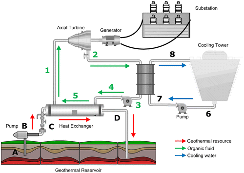
The energetic analysis of a CBC power plant, shown in Figure , was conducted using REFPROP 9.1 (Reference Fluid Thermodynamic and Transport Properties Database), acquiring thermodynamic properties of the fluids involved (water and isopentane).
In the preheater, the working fluid reaches its boiling point and then passes through the evaporator, where it comes out as saturated steam. Geothermal fluid is maintained at a higher pressure than the evaporation pressure, preventing unwanted evaporation along with the occurrence of non-condensable gases that may affect the operation of the heat exchanger, forming calcite deposits in pipes.
For the energetic evaluation and thermodynamic analysis of the cycle, components of the CBC were divided in order to proceed with the analysis. The general considerations made for each device are shown below.
| • | Turbine: Variation of kinetic and potential energies between the inlet and outlet of the turbine was considered negligible. Also, the expansion in the turbine as an adiabatic process and the mass flow of the fluid as continuous were assumptions made. | ||||
| • | Condenser: In order to dissipate the amount of waste heat required, one of the following systems must be chosen: first, a wet cooling system; second, a dry cooling system. This decision must take into account the characteristics of the location in which the power plant will be installed. | ||||
| • | Heat exchanger: It was considered that the heat exchanger is sufficiently thermally isolated; as a consequence of this, there are no thermal losses. On the other hand, the fluids are continuous and the differences between their kinetic and potential energies are negligible. | ||||
Turbine
The output power of the turbine was calculated taking into account its isentropic efficiency, based on the following equation:(1)
Condenser
The following model is used to determine the amount of heat extracted from the working fluid:(2)
Energy balance of condenser
The difference between inlet and outlet temperature of cooling water is relatively small; as a consequence of this, specific heat capacity of cooling water is considered constant. Based on Equation (Equation2
(2) ), the following equations define the energy balance in the condenser:
(3)
(4)
Notice that in order to dissipate the required amount of heat, a wet or dry cooling tower will be needed according to on-site characteristics.
Condensate pump
Isentropic efficiency of condensate pump is also taken into account for the following model expressing pump power:(5)
Shell and tube heat exchanger (preheater and evaporator)
Energy balance of the complete heat exchanger is shown in the following equation:(6)
If geothermal fluid is considered as a homogenous fluid, the left-hand side of Equation (Equation6(6) ) can be written in terms of its heat capacity and temperature:
(7)
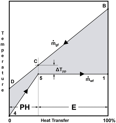
On the other hand, the heat transfer process involves two stages. Figure shows a heat transfer–temperature diagram. The upper line represents the behaviour of the geothermal fluid, while the lower line represents the behaviour of the working fluid. In the preheater stage (PH), the working fluid, as compressed fluid, increases its temperature, reaching its saturated liquid state in state 5. Considering the working fluid as a pure substance, once it is heated beyond this point, its temperature remains constant in the evaporator stage (E), being saturated steam in state 1. The minimum difference between the temperature of the geothermal fluid and the working fluid is known as pinch point, shown as . Equations (Equation8
(8) ) and (Equation9
(9) ) show the analysis of these stages:
(8)
(9)
Analysis of the complete cycle
Thermal efficiency of the cycle is calculated using the following model:(10)
Additionally, net power of the cycle () can be written in terms of input and output thermal power, using Equations (Equation2
(2) ) and (Equation6
(6) ):
(11)
Notice that Equations (Equation10(10) ) and (Equation11
(11) ) are applied to the cycle, not the entirety of the power plant. If net power is used to energise pumps, cooling tower fans, lighting or other auxiliary equipment, these secondary loads must be subtracted from
in order to obtain the net power of the plant.
Finally, second-law efficiency is obtained through the following equation, where hB and SB denote the enthalpy and entropy of the geothermal fluid at the inlet of the heat exchanger:(12)
Validation
In order to validate the final results obtained, the case study of a CBC power plant with isopentane as working fluid was considered as a reference (DiPippo Citation2012, 171–175). As a consequence of the above, 1200 kW was established as the net power of the cycle. Input data are shown in Table ; on the other hand, Table shows the data generated using REFPROP.
Table 1. Input data for CBC.
Table 2. Analysis of a CBC.
When data shown in Table are compared to the study case previously mentioned, it can be noticed that they are very similar, validating the methodology and the software used.
Flash evaporation binary cycle
Although the FEBC admits refrigerants as working fluids, taking into account the hazards discussed in previous sections, water is proposed as working fluid.
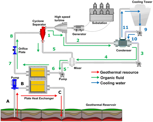
In the FEBC, shown in Figure , geothermal water heats the working fluid through the plate heat exchanger, bringing it to saturated liquid condition. Subsequently, the working fluid passes through the orifice plate, where its pressure energy decreases vaporising part of it due to sudden pressure drop (flash evaporation). The biphasic mixture generated (vapour–liquid) is led to a cyclone separator, which holds an efficiency up to 99%. Finally, the separated steam is redirected to the turbine where the steam expansion generates power; then, the liquid is reintegrated to the cycle. Regarding flash evaporation-related processes, some authors have documented the estimated lengths of the inlet and flashing stages, including the use of flow straightening vanes at the inlet (Lior and Greif Citation1979).
Outlet steam is condensed, then pressurised and taken to the mixer. Finally, the mixture of the liquid from the separator and the condensed steam is pressurised again before entering the plate heat exchanger, where the cycle is closed. Despite looking like a more complex system based on the amount of equipment used, the additional elements are simple in their characterisation and maintenance. On the other hand, the orifice plate and the cyclone separator remain as passive devices, not requiring a power source to operate.
The developed system has significant differences from conventional low-enthalpy geothermal power generation systems, and it even has advantages over it, which are the following:
| • | Very short maintenance periods, therefore high availability. | ||||
| • | Improved use of available energy due to the low pinch point of plate heat exchangers (up to 1 °C), which result in a productive extraction of energy from a sole source. | ||||
| • | The volume required for installation is relatively minor compared to CBCs. | ||||
| • | The use of water as working fluid has environmental and health benefits. | ||||
Energetic evaluation of a FEBC
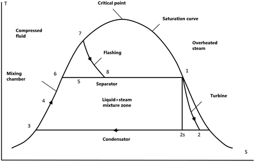
The energetic analysis is presented according to the thermodynamic principles of mass and energy conservation. In order to understand the thermodynamic processes occurring in the FEBC, a temperature vs entropy diagram is shown in Figure .
Taking the analysis conducted for the CBC as a background, the components for the FEBC will also be analysed separately, with the main devices being the following: turbine, condenser and pumps; the methodology, considerations and equations used for the analysis of the CBC are used again for the analysis of the FEBC. Specific considerations regarding the added components to the FEBC are shown below:
| • | Orifice plate: Working fluid, pressurised and in a compressed fluid state, receives thermal energy from geothermal fluid in state 7 (see Figures and ). As stated in previous sections, once the fluid passes through the orifice plate, a sudden change in phase occurs, bringing the fluid into a mixture of liquid and steam. In order to reach a pressure drop of 2 bar, a single orifice plate or multiple orifice plates may be needed. Flash evaporation carried out in the orifice plate is calculated as an isenthalpic process (h7 = h8) because the process occurs spontaneously, is essentially adiabatic and it does not involve any type of work (DiPippo Citation2012, 91). Additionally, any change in kinetic or potential energy of the fluid is neglected. | ||||
| • | Cyclone separator: The resultant mixture from the orifice plate enters the flow separator, which delivers saturated liquid, as well as saturated steam. The separation process is calculated at constant pressure (isobaric). | ||||
Finally, steam fraction in the cyclone separator is calculated through an energy balance regarding steam and liquid coming out of it:(13)
(14)
Comparison of the energetic performance of both cycles
In order to complete the comparison of energetic performance and efficiency, the input values for both cycles were established, as shown in Table . It is noteworthy that the proposed net power is 1200 kW, and the inlet temperature of the geothermal fluid is 140 °C; regarding heat exchangers, the pinch point for the CBC is set to 5 °C, while in the FEBC is set to 3 °C. Since the FEBC uses a plate heat exchanger, its pinch point could theoretically reach 1 °C. Another difference is the fact that the CBC has a turbine inlet pressure of 1 MPa, whereas the FEBC has an inlet pressure of 0.1 MPa, affecting the parameters of the condenser and the mass flow rate of cooling water. The above is an after effect of the working fluid being different in each cycle and the temperature of the geothermal fluid.
Table 3. Input data for the energetic comparison.
Results
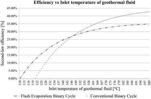
Table shows the main comparative data for energy efficiency, with a 1200 kW power output, in which it is observed that the FEBC is within a consistent range with those of a CBC. In order to get a wider vision of these results, graphs of the most relevant parameters are also shown. Figure shows the variation in efficiency if the inlet temperature of the geothermal fluid is modified.
Table 4. Theoretical comparison of a CBC and a FEBC with a power output of 1200 kWe.
Figure also helps to define the range of optimum operation for each cycle. If a geothermal resource below 146 °C is available, the most efficient option would be the FEBC. On the other hand, if the temperature of the geothermal reservoir is above that temperature, it is advisable to use a CBC.
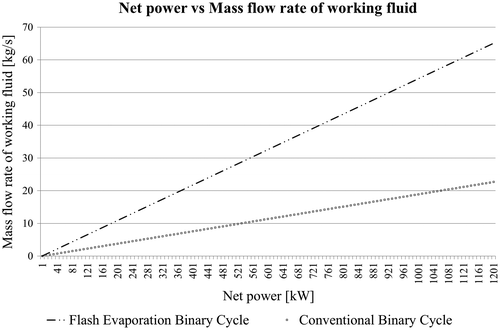
Figure shows that the mass flow rate of working fluid in the FEBC is much greater than the mass flow rate needed in CBC. It is also a remarkable fact that the working fluid in the CBC is water, and, in the case of FEBC, the working fluid is isopentane, which should be treated with caution for experimental purposes, as it is not as accessible as water.
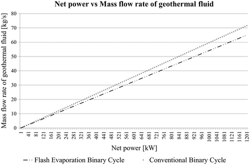
In addition, Figure shows that the FEBC has an improved performance in terms of the required mass flow rate of the geothermal fluid. Although the difference is not drastically wide, this fact may be an important factor when choosing the cycle to be used in a shallow reservoir.
Conclusions
This article presented an alternative for power generation with a single-flash-modified binary cycle (FEBC), which, according to the results of the energetic comparison, it may be a good option for power generation using low-enthalpy geothermal energy.
The main advantage of the FEBC over a CBC is that, when using a plate heat exchanger, an orifice plate and a cyclone separator, efficiency of steam generation is increased; besides, the volume occupied by plate heat exchangers is less than the volume of shell and tube heat exchangers. In addition, maintenance of a plate heat exchanger is simplified.
The results obtained in this study demonstrate that if a geothermal resource below 140 °C is available, and it is installed in a location with an ambient temperature of 25 °C, the FEBC offers an improved performance compared to a CBC. This may be a new area of opportunity for power generation not only with low-enthalpy geothermal energy, but also with other renewable sources such as solar. Finally, according to the energetic requirements of the FEBC, it may also employ waste heat as hot reservoir, providing a new way to exploit heat recovery in industrial applications.
| Nomenclature | ||
| = | mass flow rate | |
| = | heat transfer rate | |
| = | net power | |
| = | mean heat capacity | |
| CBC | = | conventional binary cycle |
| CFE | = | Comisión Federal de Electricidad |
| FEBC | = | flash evaporation binary cycle |
| GWP | = | global warming potential |
| h | = | enthalpy |
| iiDEA | = | Instituto de Ingeniería – Desalación y Energías alternas |
| ODP | = | ozone depletion potential |
| S | = | entropy |
| T | = | temperature |
| UNAM | = | Universidad Nacional Autónoma de México |
| X | = | steam fraction |
| η | = | efficiency |
| Subindexes | ||
| 0 | = | dead state at 25 °C |
| B | = | inlet of heat exchanger (geothermal fluid) |
| c | = | condenser |
| cw | = | cooling water |
| E | = | evaporator |
| gf | = | geothermal fluid |
| p | = | pump |
| PH | = | preheater |
| pp | = | pinch point |
| s | = | isentropic |
| t | = | turbine |
| th | = | thermal |
| wf | = | working fluid |
Disclosure statement
No potential conflict of interest was reported by the authors.
Notes on contributors
Héctor Miguel Aviña Jiménez, PhD, is the Technical Coordinator of iiDEA, applied research group part of CeMIE-Geo. His main research interest is the exploitation of low-enthalpy geothermal energy though the technological development of a power generation cycle, a seawater desalination unit and a food dehydrator.
Gabriel León de los Santos, PhD, is a professor of Electrical Engineering at the National Autonomous University of Mexico, with power plants, steam generation systems, process engineering and efficient energy use as his main research topics.
Miguel Ángel Benítez Torreblanca, B.Eng, is a graduate student focusing on the design of fault-tolerant instrumentation and control systems for geothermal projects.
Acknowledgments
The authors would like to thank Project P11, part of the Mexican Centre for Innovation in Geothermal Energy (CeMIE-Geo).
References
- Alcocer, S. M., and G. Hiriart. 2008. “An Applied Research Program On Water Desalination With Renewable Energies.” American Journal of Environmental Sciences 4 (3): 204–211. doi:10.3844/ajessp.2008.204.211.
- Aviña, Héctor, O. Ramos, and J. Hernández. 2012. “Propuesta del diseño analítico para una turbina experimental para micro-generación.” Paper presented at XII Congreso y exposición latinoamericana de turbomaquinaria, Querétaro, México, February 21–25.
- DiPippo, Ronald. 1999. “Small Geothermal Power Plants: Design, Performance and Economics.” Geo-Heat Center Quarterly Bulletin 20 (2): 1–9.
- DiPippo, Ronald. 2004. “Second Law Assessment of Binary Plants Generating Power from Low Temperature Geothermal Fluids.” Geothermics 33 (5): 565–586. doi:10.1016/j.geothermics.2003.10.003.
- DiPippo, Ronald. 2012. Geothermal Power Plants: Principles, Applications, Case Studies and Environmental Impact. New York: Butterworth-Heinemann.10.1016/B978-0-08-087872-0.00708-3
- Edrisi, Baktosh H., and E. E. Michaelides. 2012. “Effects of the Working Fluid on the Optimum Work of Binary-Flashing Geothermal Power Plants.” Energy 50: 389–394. doi:10.1016/j.energy.2012.10.025.
- Entingh, D. J., E. Easwaran, and L. McLarty. 1994. “Small Geothermal Electric Systems for Remote Powering.” GRC Transactions 18: 39–46.
- Gu, Zhaolin, and H. Sato. 2002. “Performance of Supercritical Cycles for Geothermal Binary Design.” Energy Conversion and Management 43 (7): 961–971. doi:10.1016/S0196-8904(01)00082-6.
- Gnutek, Z., and A. Bryszewska-Mazurek. 2001. “The Thermodynamic Analysis of Multicycle ORC Engine.” Energy 26 (12): 1075–1082. doi:10.1016/S0360-5442(01)00070-6.
- Kanoglu, Mehmet. 2002. “Exergy Analysis of a Dual-Level Binary Geothermal Power Plant.” Geothermics 31 (6): 709–724. doi:10.1016/S0375-6505(02)00032-9.
- Kose, Ramazan. 2007. “Geothermal Energy Potential for Power Generation in Turkey: A Case Study in Simav, Kutahya.” Renewable and Sustainable Energy Reviews 11 (3): 497–511. doi:10.1016/j.rser.2005.03.005.
- Lior, Noam, and R. Greif. 1979. “A System for the Experimental Study of Flash Evaporation.” Desalination 31 (1–3): 87–99. doi:10.1016/S0011-9164(00)88507-0.
- Michaelides, Efstathios E., and G. J. Scott. 1984. “A Binary-flashing Geothermal Power plant.” Energy 9 (4): 323–331. doi:10.1016/0360-5442(84)90103-8.
- Ordaz Méndez, C. A., M. Flores Armenta, and G. Ramírez Silva. 2011. “Potencial geotérmico de la República Mexicana.” Geotermia 24 (1): 50–58.

