
Abstract
The aim of this work is to analyse the performance of a solar energy collector system for water and air heating in real working conditions. Two coupled mathematical models have been developed. One of them describes the thermal behaviour of the Hybrid Solar Collector (HSC) and the second one describes the simultaneous operation of the HSC and of a fully mixed water storage tank. The dependence of the performance of the HSC system on the following three parameters has been studied: (1) water and air mass flow rate; (2) water pipe diameter and air channel height; (3) water storage tank volume. The mathematical models were used to evaluate the HSC system performance during 29 different days, covering all four seasons. A higher water flow rate generally enhances the thermal efficiency of the HSC system, but the enhancement became significantly smaller at higher air flow rates. Positive but small values are recommended for the difference between the fluid temperature at solar collectors exit and the water temperature in the tank. The thermal efficiency of the HSC system is higher on nearly clear sky and decreases in case the amount of clouds on the sky increases.
Introduction
Solar energy is an economical alternative to today’s energy demand. There is an increasing interest in solar energy utilisation for different purposes. For instance, hybrid photovoltaic/thermal (PV/T) solar systems have been designed and manufactured. The main advantage of this type of solar system is the simultaneous production of both electricity and hot water/air (e.g. Badescu, Landsberg, and De Vos Citation1997; Herrando, Markides, and Hellgardt Citation2014; Herrando and Markides Citation2016). Also, solar energy can be used for water and air heating. There are many studies concerning solar water heating and solar air heating technologies (Menzies and Roderick Citation2010).
In any solar water system, the amount of energy required to heat the cold water is dependent on many factors, such as the location and orientation of the solar system, temperatures of the water inlet and outlet and the desired hot water set temperatures (Azad Citation2012). For instance, Jaisankar, Radhakrishnan, and Sheeba (Citation2009) have been investigated experimentally the efficiency of a thermosyphon flat plate solar collector system where the heat transfer has been enhanced by using tapes with spacers. Different design configurations were studied in that paper. Picón-Núñez, Martínez-Rodríguez, and Fuentes-Silva (Citation2014) have proposed a design solution for networks of solar collectors in order to meet the thermal energy demand and also to keep pressure losses within the acceptable range. Khamis (Citation2013) investigated the effectiveness of a new solar flat plate collector based on minichannels. The performance has been compared with that of several conventional solar collectors (flat-plate, evacuated-tube and heat-pipe collector). For this purpose, the author created a numerical mathematical model which was validated against experimental measurements. He also examined the performance of the new collector for different mass flow rates of the working fluid. A mathematical model consisting of four differential equations that describe the energy balance for the components of a flat-plate solar collector was presented by Hamed, Fellah, and Ben Brahim (Citation2014). The system of equations has been solved by using the Runge–Kutta method under the MATLAB environment. The authors studied the influence of different parameters (working fluid mass flow rate and inlet temperature, number of pipes) on the collector performance. A water heating system composed of a solar collector and a water tank was studied experimentally by Razika et al. (Citation2014). The incident flux of solar energy has been simulated using a high power electric lamp. The dependence of the collector efficiency on the working fluid mass flow rate and collector tilt angle has been analysed. The insulation effects of the solar water heaters have been studied by Andoh et al. (Citation2010) where experiment study was conducted to evaluate the thermal performance of a solar water heater using a vegetable fibre, coconut coir as heat insulation. Hasan (Citation1997) studied the influence of the hot water tank volume and configuration on the effectiveness of a thermosyphon solar water heater system. Simulations were performed by using a model implemented in TRNSYS. The conclusions were that the efficiency increases when the volume of the tank is increasing. Also, the performance of vertical tanks is similar with that of horizontal tanks. Buonomano, Calise, and Ferruzzi (Citation2013) used different control strategies for the thermal storage management in order to optimise the operation of a solar heating and cooling system. Studies about the effects of volumetric flow rate on the performance of a solar thermal collector have been carried out by Ziqian et al. (Citation2012) and Ihaddadene et al. (Citation2014). These studies have shown that the increase in volumetric flow rate resulted in an increase in collector efficiency. For flow rates reduced by up to 75% the solar collector efficiency is only reduced by approximately 10–15%. Buonomano et al. (Citation2014, 293) presented the analysis of a combined system for solar heating and cooling, composed of a field of evacuated solar collectors, a single-stage LiBr–H2O absorption chiller and a gas-fired boiler for the supply of auxiliary thermal energy. A model developed in TRNSYS was used to examine the effect of different control strategies as a function of climate. The results showed that a parallel charging/discharging operation strategy is to be preferred. Moreover, although a reduction in natural gas consumption is achieved, a higher amount of gas is needed for domestic water heating.
Pottler et al. (Citation1999) performed an optimisation of the fin geometry for a solar air preheater mounted on a south facing wall of a building located in Würzburg, Germany. The authors studied several fin and absorber plate configurations in order to find the design with the best performance. They found that finned absorbers perform much better and that offset strip fins yield high net energy gains for large fin spacing. Panna, Deshpandey, and Jena (Citation2015) have been studded experimentally the thermal performance of the packed bed solar air heat storage system under varying solar irradiance and ambient air temperature in different months. The authors found the heat retrieval efficiency of the packed bed filled with rock pebbles better as packed bed filled with phase change material. The flow rate has been optimised for indirect forced circulation solar water or air heating systems by Yan et al. (Citation2013).
Some researchers have studied the thermal performance of solar collectors working with two different types of fluids simultaneously. Assari, Basirat Tabrizi, and Jafari (Citation2011, 601–608) studied the performance of a Dual Purpose Solar Collector (DPSC) (it is also called as Hybrid solar collector HSC) consisting of a combination between an air heater and a water heater. The authors developed a mathematical model based on the effectiveness method. They investigated the thermal performance of the HSC. The efficiency of a HSC was compared by Nematollahi, Alamdari, and Assari (Citation2014) with that of a single purpose solar water heating system. The authors concluded that the efficiency achieved by using the HSC system is about 3–5% higher compared to that of a single purpose solar water system. This clearly indicates the advantage of using a HSC in terms of enhanced heat delivery and thermal efficiency. Venkatesh and Christraj (Citation2014, 2) designed a HSC. Also, the storage tank was modified into riser tubes and header, fitted in the bottom of the solar air heater. Fins were added to the riser tubes in order to increase the performance of the multipurpose solar heating system. Ma et al. (Citation2011) investigated experimentally and theoretically the efficiency of a double-flow solar heater with L-shaped fins to increase the heat transfer on the air side of the collector. Mohajer et al. (Citation2013) investigated experimentally the performance of a HSC used to dry parsley, dill and coriander. The collector is part of a hybrid system which provides hot air for vegetables dryer and hot water simultaneously. The experiments showed that the system can support both the drying process and the water heating. Venu and Arun (Citation2013, 114–120) investigated theoretically the performance of a DPSC with a porous matrix inserted below the absorber plate, and compared it with a conventional one, without porous matrix. ANSYS 13 and associated Fluent CFD package were used for simulations. The results indicated that the use of porous medium increases the performance of the collector, compared to the existing design of HSC. Jafari et al. (Citation2011, 1712) performed an energy and exergy analysis of a HSC. The results showed that HSC has better energy and exergy efficiency than the single purpose solar collector. The air section of the HSC increases heat delivery and collector efficiency significantly at higher water inlet temperature. Exergy analysis indicated that the air part can increase the exergy efficiency of the HSC. Varghese and Jino (Citation2016) investigated experimentally the thermal performance of solar collectors that are using a mixture of two working fluids: air and water. A dynamic numerical model has been developed and validated against the experimental data provided by Ji et al. (Citation2011) during studies concerning the operation of a new building-integrated, dual-function, solar collector that is able to provide passive space heating in winter and hot water in the warm seasons. It was found that the solar collector performs well in providing hot water in the warm seasons without raising space overheating problems in summer.
Previous studies focus on the thermal performance of a separate HSC. There are still few studies concerning the performance of systems consisting of HSCs (see, e.g. Assari, Basirat Tabrizi, and Jafari Citation2011; Jafari et al. Citation2011). One of these studies (Assari, Basirat Tabrizi, and Jafari Citation2011, 605) focus on the water inlet temperature and air flow without studying the performance for different water flow rates. Venkatesh and Christraj (Citation2014, 7–8) studied the performance of the HSC for three constant values of the water mass flow rate. Results reported by Venu and Arun (Citation2013, 116) showed that using a porous medium integrated with the HSC increases the heat delivery and thermal efficiency.
This paper focuses on the design of a HSC system and its operation. Two mathematical models that evaluate the performance of the HSC system are presented. One model deals with the HSC and the other model refers to the HSC system, consisting of the HSC and a fully mixed water storage tank. The model of the HSC is mainly inspired by the work of Assari, Basirat Tabrizi, and Jafari (Citation2011, 605). However, several improvements have been performed, which will be specified in this paper.
The thermal efficiency of the HSC system is evaluated in days with different levels of stability of the radiative regime. Note that the dependence of the collector performance on the level of solar irradiation has been studied by many authors (see e.g. Guarracino et al. Citation2016; Schnieders Citation1997, among many others). However, the focus here is not on the level of solar irradiation but on the stability of the radiative regime, since different radiative regimes may be associated with the same level of solar irradiation.
The water mass flow rate in the collector is the control parameter. To our best knowledge, the literature is lacking in studies on the optimum mass flow rates for both water and air, simultaneously, as well as in studies dealing with the optimisation of water pipe size and air channel shape, simultaneously. In this work, we optimise both the flow rate of water and the flow rate of air. This is a novelty in respect with the previous approach by Venkatesh and Christraj (Citation2014, 9). Also, we study how different sizes of the water pipe diameter and height of the air channel influence the performance of the HSC system. This fills the gap in the work by Venu and Arun (Citation2013, 115) who did not study different geometrical configurations of the water pipes and air channels. Also, a further target is to figure out the appropriate size of the water storage tank.
Description of the HSC
Collector description
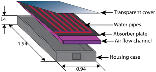
The purpose of a HSC is to convert solar energy into heat. The heat is transferred to the water and air circulating into the collector pipes and air channel, respectively. The layout of the proposed HSC is shown in Figure . It consists of a flat plate solar collector with a transparent cover made of glass, on the upper part. A black metal absorbing plate was welded in the centre of the collector. Ten water copper pipes were placed above the plate and an air flow channel without fins was placed below the plate. The absorber plate covers the full aperture area of the collector and it is fixed 30 mm below the glass cover. It collects the solar energy and transfers it to the water flowing at the top and to the air that flows below. The rear and the side of the collector are insulated by a polystyrene sheet, in order to minimise heat loss. In this study the collector was considered south facing and inclined at 30° from horizontal.
Figure 1. Details of HSC design (all dimensions are in m).
Collector modelling
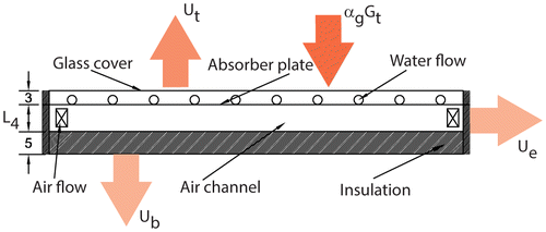
Solar global irradiance GT is absorbed by the plate at temperature Tpm. Figure shows the thermal layout that was used to calculate the heat fluxes in the collector. The energy is transferred from the absorber to the working fluids (water and air, flowing inside the water pipes and air channel, respectively) at a rate given by convection heat transfer coefficients hw and ha, respectively. Some of the heat is lost to the environment through the glass cover and through the collector box bottom and edge surface.
Figure 2. Heat transfer mechanisms through the HSC (all dimensions are in cm).
The mathematical model of the HSC is similar to the one presented by Assari, Basirat Tabrizi, and Jafari (Citation2011, 605), with four improvements which will be specified in the following paragraphs.
The first step is the computation of the heat lost from the collector. A glass cover is covering the collector to prevent most of the heat losses by convection and radiation from the absorber into the environment. The overall heat loss from the HSC is based on the mean plate temperature and can be represented as:(1)
where Qloss is the overall heat loss flux from the collector [W], Ac is the gross collector area [m2], Tpm is the mean plate temperature [K], Tamb is ambient temperature [K] and UL is the overall collector loss coefficient, which includes heat losses from the collector to its surroundings by conduction, infrared radiation and convection. The overall collector loss coefficient is equal to the sum of the top loss, Ut, the bottom loss, Ub, and the edge loss coefficient, Ue [W/(m2∙K)]:(2)
The top heat loss coefficient Ut in Equation (Equation2(2) ) is given by (Malhotra, Garg, and Palit Citation1981):
(3)
(4)
(5)
where N is the number of transparent covers, εP is the emissivity of absorber surface for long wavelength radiation, εc is the emissivity of cover for long wavelength radiation, β is collector slope (or tilt angle) and h∞ is the convection heat transfer coefficient at the top of the glass cover due to wind [W/(m2 K)]. The first difference between the presented model and the model of (Assari, Basirat Tabrizi, and Jafari Citation2011, 605) is the wind convection coefficient formula. Here it is calculated by the following a simple relation (Kalogirou Citation2009), which is frequently used in flat-plate collectors modelling:(6)
where V∞ is the free stream wind speed [m/s].
Good thermal insulation is used in the HSC. The heat loss coefficients in Equation (Equation2(2) ), which account for the conductive heat loss through the bottom and the edge of the solar collector, Ub and Ue, respectively, can be obtained from (Ghassan, Mohannad, and Atif Citation2011):
(7)
(8)
where L1 is the length of absorber plate [m], L2 is the width of absorber plate [m], L3 is the height of collector casing [m], Ki is the insulation thermal conductivity [W/(m K)] and δb, δe are thickness of bottom and edge insulation [m], respectively.
The convection heat transfer coefficient hf between the hot fluid (water or air) and walls of water tube or air channel [W/(m2 K)] was calculated from the relationship:(9)
where kf and Dh are the thermal conductivity of working fluids [W/(m∙K)] and hydraulic diameter [m] of water pipes and air channel, respectively. The subscript f refers to the working fluid, water or air, while:(10)
Also, Nuf, which is the Nusselt number, is a function of Reynolds number of the flow, which is given by:(11)
where vf is the mean velocity over the tube cross section [m/s] and μf is kinematic viscosity of fluid [kg/(m s)].
Another change with respect to the model of Assari, Basirat Tabrizi, and Jafari (Citation2011, 605) includes the equation of the Nusselt number. Assari, Basirat Tabrizi, and Jafari (Citation2011, 605) refer to laminar flow. Here, because of the more complex geometry and different fluid flow rates, we are dealing with both laminar and turbulent flowing regimes. For this reason, we are using the following set of equations which are different from the Nusselt formula that was used by Assari, Basirat Tabrizi, and Jafari (Citation2011, 605):
| • | For the water laminar flow case, the Nusselt number depends on the Prandtl number Pr (which is the ratio of the kinematic viscosity, also referred to as the momentum diffusivity, to the thermal diffusivity) and Graetz number GzD (Baehr and Stephan Citation2006): | ||||
(12)
(13)
(14)
| • | For the turbulent flow of water (Winterton Citation1998): | ||||
(15)
| • | For the air flow inside the channel without fins the Nusselt number is calculated using the following equation (Kays, Crawford, and Weigand Citation2005): | ||||
(16)
Note that the flowing regime may change from laminar to turbulent in case of increasing fluid speed. The improved heat transfer model increases the accuracy of the results reported in dependence of HSC system performance on flow rate section, where the dependence of the HSC system performance on flow rate is studied. The thermal efficiency values presented in Figure would be smaller in case of larger flow rates, if the laminar relationships proposed by Assari, Basirat Tabrizi, and Jafari (Citation2011, 605) would be used. Also, when the mass flow rate is kept constant, the fluid speed increases when passing from larger to smaller pipe diameters. Therefore, one expects that the improved heat transfer model would increase the results accuracy in dependence of HSC system performance on design parameters section where the dependence of the thermal efficiency on the water pipe diameter Dpipe and air channel height L is discussed. The thermal efficiency values presented in Figure for smaller values of Dpipe and L would be smaller in case of using the laminar relationships proposed by Assari, Basirat Tabrizi, and Jafari (Citation2011).
In steady-state conditions, the useful energy taken by the working fluid flowing through the HSC depends on the available energy, (τα)∙GT, and the energy losses from the system. Using the plate mean temperature Tpm of the collector, the useful energy is given by (Duffie and Beckman Citation1991):(17)
where τα is effective transmittance–absorptance product.
The collector heat removal factor FR, relates the actual useful energy gain of a collector to the useful gain, if the whole collector surface would be at the working fluid inlet temperature (Assari, Basirat Tabrizi, and Jafari Citation2011, 606):(18)
where εf, and Cp,f are heat exchange effectiveness, mass flow rate [kg/s] and specific heat [J/(kg K)] for water or air, respectively, and Af is the fluid heat transfer area [m2].
(19)
When the whole collector is at the inlet fluid (water or air) temperature Tf,in, the maximum possible useful energy gain in a HSC is achieved. The product of the collector heat removal factor FR and the maximum possible useful energy gain gives the actual useful energy gain Qu, allowing rewriting of Equation (Equation17(17) ) (Kalogirou Citation2009):
(20)
Hybrid solar energy system
System description
The HSC system performance is highly dependent on the concordance between the solar availability and the heating demand. The HSC collects the solar energy and heats the water flowing through the collector pipes. Part of the potential heat losses by the solar water heating collector are recovered by the air flowing below the absorber plate (see Figure ). The air flow is driven by a fan. The air is sucked from the atmosphere through a rectangular duct of cross section 0.01 m2 and is delivered to the user through another rectangular duct of similar size. The air channel is made of aluminium panels with size 1.94 m × 0.94 m × 0.1 m. In order to increase the heat gain, it is necessary to store the hot water in a storage tank. In other papers (Jafari et al. Citation2011; Venu and Arun Citation2013, 115, 1712) the working of the collector was studied separately, without a storage system. The system studied here is shown in Figure . It is a closed circuit system which consists of a flat-plate HSC with surface area Ac and a storage tank containing a mass Mw of water. Table shows the main system design parameters.
Figure 3. Forced circulation HSC system with water storage tank
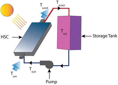
Table 1. Design parameters.
Solar collection systems based on large water storage tanks are rather popular in southern European countries, where solar energy is abundant during summer. Large tanks, allowing stratified operation, make the systems energetically more effective. In northern European countries smaller storage tanks are in common usage (Bales and Persson Citation2003) since the amount of incoming solar energy is also smaller. Usually, stratified operation is not possible for small storage tanks or in case the hot water demand profile is spread all over the day. In such cases the fully mixed regime is a better physical approximation and is used in the present analysis.
Water enters the solar collectors at inlet temperature Tw,in while the air inlet temperature, Ta,in, is equal to the ambient temperature. After extracting heat from the absorbing plate, the hot water and the hot air exit the collector at temperatures Tw,out and Ta,out, respectively. The solar energy collected by the water flow is accumulated as thermal energy in the fully mixed water storage tank at temperature Tw,s. A pump is installed between the collector and the storage tank. It operates almost continuously, during days with cloudy or clear sky. An ON/OFF differential controller generates the ON/OFF signals for the pump operation. The pump is controlled by a differential thermostat that turns on when the water temperature at the exit of collector is higher than the water temperature in the storage tank.
System modelling
The following assumptions are adopted for the model of the HSC system:
| (1) | The absorber, water tubes, air channels, bottom and side surfaces are all at mean plate temperature (Tpm). | ||||
| (2) | The physical properties of the solid bodies (absorber, glazing and thermal insulation) are constant. | ||||
| (3) | The conduction and radiation heat transfer in water tubes and air channel is neglected. | ||||
| (4) | The rear and side areas of the collector are relatively small and well insulated; so the thermal losses from them by convection and radiation are neglected. | ||||
| (5) | The water storage tank is entirely insulated and fully mixed, i.e. the temperature of the water in the tank is uniform. | ||||
| (6) | The heat loss from the water pipes connecting the collector and the storage tank is neglected; so, the water temperature at the solar collector inlet is equal to the water temperature at the exit from the storage tank. | ||||
The first law of thermodynamics applied to the water in the storage tank is:(21)
where Mw Cp,w is the product of mass and specific heat of water in the storage tank, t is the time, Tw,s is the water temperature in the fully mixed water storage tank, Qin,w is the energy transferred from the solar collector to the storage tank and Qloss is the energy loss from the storage tank.
The useful energy gain is a popular method for on– off pump control in forced-circulation solar water collector systems. The difference of two reference temperatures, the water temperature at collector outlet (Tw,out) and the water temperature in the storage tank (Tw,s), respectively, is used to control the pump operation (see Figure ). When the difference between these two values is greater than 0 °C the pump turns on and the useful energy gain is greater than zero. The pump turns off if the temperature difference reaches the lower set value of 0 °C. The heat flux transferred from the solar collector to the water storage tank is given by (Badescu Citation2008):(22)
When the air heating is considered, the thermal energy gain is associated with the increase of the air flow temperature between outlet (Ta,out) and inlet (Ta,in), i.e.:(23)
The daily thermal energy accumulated in the water tank, , and the daily thermal energy transferred to the air flow,
, are obtained by integrating Equations (Equation22
(22) ) and (Equation23
(23) ) over the solar system operating period, from the moment tr of sunrise to the moment ts of sunset:
(24)
(25)
The total thermal energy gained by the HSC system during the day, is obtained from the sum of equations (Equation24(24) ) and (Equation25
(25) ):
(26)
The daily HSC system efficiency is defined as:(27)
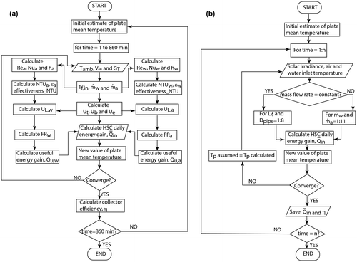
A computer program was developed to simulate the performance of the HSC system. Assuming one-dimensional heat transfer, an iterative procedure is used to estimate the top heat loss coefficient. Equations (Equation1(1) –Equation20
(20) ) were implemented into the MATLAB environment to compute the actual useful energy gain Qu by the collector. The first step is the calculation of the overall heat loss from the collector and the water and air exit temperatures. In order to predict the performance of the HSC system, we calculated the daily thermal energy accumulated by water and air (Equations (Equation24
(24) ) and (Equation25
(25) ), respectively). All simulations in this work are computed with a time step equal to 15 s. The simulation Flowcharts are given in Figure .
Figure 4. Simulation flow chart
Model validation
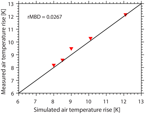
The mathematical model proposed here refers to solar collectors with three different types of air channels. In this section we consider only the case of an air channel without fins. The air temperature rise at different values of water inlet temperature determined from the HSC model has been compared with the values obtained from experimental data for smooth ducts reported by Assari, Basirat Tabrizi, and Jafari (Citation2011, 606). Figure shows simulated and measured air temperature rise at constant water inlet temperature 40 °C and instantaneous solar irradiance 900 W/m2, for different air flow rate (0.2, 0.4, 0.6, 0.8 and 1 kg/s, respectively). There is good agreement between simulated and measured air temperatures rise (relative mean bias difference (rMBD) is 2.67%). Therefore, the mathematical model may be used to perform enough accurate simulations.
Figure 5. Air temperature rise (Ta,out − Ta,in, see Figure ) simulated by the present model and measured by Assari, Basirat Tabrizi, and Jafari (Citation2011).
Meteorologic data
Indicators describing the state of the sky
The solar radiation intercepted at the earth’s surface is of paramount importance for different applications (Sekar et al. Citation2012). In order to describe the state of the sky, two indirect measures are used, i.e. the sunshine number and the sunshine stability number, respectively.
The sunshine number ξt is a binary quantity, indicating whether the sun shines or not at given time t (Badescu Citation2002):(28)
The average value over the time interval ∆t equals the relative sunshine σ during ∆t, i.e.
.
Series of ξt were derived from series of measured solar irradiance by using the sunshine criterion (WMO-No.8 Citation2014), i.e. the sun is shining at time t if direct solar irradiance exceeds 120 W/m2:(29)
where Gt and Gd,t denote the global and diffuse solar irradiance at the moment t, respectively, and h is sun elevation angle. Measurements associated with ht < 5° have not been used for the following two reasons: (i) the pyranometer’s accuracy around sunrise and sunset is questionable; (ii) sin(ht) tends towards zero for small values of ht and, consequently, Equation (Equation29(29) ) tends to provide ξ = 1, independent of the values of Gt and Gd,t (Li and Lam Citation2011; Rangarajan and Swaminathan Citation1984).
The sunshine stability number ζt quantifies the stability of the solar radiative regime (Paulescu and Badescu Citation2011):(30)
During a time interval ∆t the sun may be covered by clouds several times. Therefore, the stability of the radiative regime during that interval was characterised by the mean value of sunshine stability number, denoted . It takes values between 0 (in case that there is only one value of ζt (i.e. 0 or 1) during the ∆t interval; this case corresponds to fully stable radiative regime), and ½ (in case ζt values are always changing between two consecutive moments during the interval ∆t; this corresponds to the fully unstable radiative regime).
Modelling solar radiation on tilted surface
In this paper solar irradiance measurements performed at Timisoara, Romania (latitude 45º46′N, longitude 21º25′E, 85 m altitude above mean sea level) were used. Timisoara has a temperate continental climate and an Ivanov index of continentality 130.9 (Badescu Citation1999). Monthly minimum, average and maximum ambient temperatures recorded over the years are 5.2 °C, −1.5 °C and 2.7 °C, respectively, (in January) and 15.1 °C, 21.5 °C and 28.2 °C (in July), respectively (Badescu and Zamfir Citation1999).
Ambient temperature and solar global and diffuse irradiance on horizontal surface have been recorded at time intervals of 15 s during year 2009 at the Solar Radiation Monitoring Station of the West University of Timisoara (http://solar.physics.uvt.ro/srms 2014). High accuracy of data was ensured by an acquisition data system based on National Instruments PXI Platform including a PXI-6259 data acquisition board. Also, DeltaOHM LP PYRA 02 first class pyranometers were used, which conform to ISO 9060 standards and are in agreement with the World Meteorological Organization specifications.
A simple isotropic model was used to calculate the total solar irradiance GT on tilted collectors surface (see, Badescu and Rotar Citation2012):(31)
where: β is the surface tilt angle (in this case β = 30°), θ is the direct radiation incidence angle, βz is the solar zenith angle and ρ is the ground albedo (here assumed ρ = 0.2). The incidence angle θ is calculated with the following formula:(32)
where δ is solar declination angle, φ is the latitude, ω is the solar hour angle and γ is the azimuth angle (=0 for a South oriented surface). For a horizontal surface (β = 0), the angle θ in Equation (Equation32(32) ) reduces to the solar zenith angle θz. The declination angle δ, in degrees, for any given Julian day n ranging between 1 and 365 (or 366) may be calculated in first approximation with the Cooper formula:
(33)
The hour angle ω is defined as zero at local solar noon (when the sun’s altitude angle is at its greatest). The hour angle decreases by 15º for each hour before local solar noon and increases by 15° for each hour after solar noon.
Selection of days with different radiative regime
In this paper simulations have been performed 29 days presented in Table . These days belong to different sunshine classes and different classes of stability of the radiative regime (i.e. less stable and more stable, respectively). The days of Table may be seen as characteristic for the four seasons at mid latitude in the Northern Hemisphere.
Table 2. Selected days during 2009 at Timisoara. The daily average values of the sunshine number (SSN) and sunshine stability number (SSSN) are also shown.
Results and discussion
The thermal efficiency of solar thermal collectors depends on design parameters, operation conditions and weather. The matching between the collector design and the mass flow rate of the working fluids is very important to achieve effective HSC systems. Therefore, an objective of this paper is to investigate the dependence of solar energy conversion efficiency on the mass flow rate of the working fluids (water and air), the diameter of the water pipes and the height of air channels. In first section below the effect of the flow rates on the solar energy conversion efficiency is presented. The effect of the size of water pipes and air channels on the conversion efficiency is studied in second section. In third section below (Dependence of HSC system performance on storage tank volume) the effect of the tank volume on the conversion efficiency and the level of water temperature inside the storage tank is analysed.
Dependence of HSC system performance on flow rate
Several values of the water and air mass flow rates, ranging from 0.01 to 0.14 kg/s (0.006–0.077 kg/(s m2)), have been used as inputs and the effect on the daily performance of the HSC system has been evaluated. Also, various air inlet temperatures in HSC system have been considered. The tank volume was assumed constant, i.e. 300 L. The total daily efficiency has been evaluated for all 29 days in Table . Detailed results are presented in the Electronic Supplementary Material (ESM).
Here we present results for only four days, one day in each season, as follows: a medium cloudiness day in winter with 0.509 sunshine number and 0.021 sunshine stability number (19 January 2009), an overcast sky day in spring with 0 sunshine number and fully stable radiative regime (28 May 2009), a high cloudiness day in summer with 0.258 sunshine number and 0.006 sunshine stability number (2 July 2009) and a low cloudiness day in autumn with 0.882 sunshine number and 0.002 sunshine stability number (25 November 2009). Time variation of several meteorological parameters for these four days is shown in Figure (a).
Figure 6. Time variation of (a) solar global irradiance, G, and ambient air temperature, Tamb, for four different days in winter, spring, summer and autumn; (b) water temperature in the storage tank, Tw,s; (c) water mass flow rate, m w; (d) dependence of the collector total daily efficiency, , on water mass flow rate.
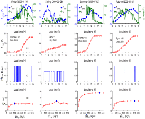
The water temperature in the fully mixed storage tank depends on the level of the solar global irradiance, as shown in Figure (b). The maximum water temperature in the storage tank was 313 K, obtained in summer (on 2 July 2009) at a constant mass flow rate for water and air 0.12 and 0.04 kg/s (0.066 and 0.022 kg/(s m2)), respectively. The minimum water temperature in the storage tank was 299 K, obtained in the Spring (in the fully stable, overcast sky day 28 May 2009) at a constant mass flow rate for water and air 0.08 and 0.04 kg/s (0.044 and 0.022 kg/(s m2)), respectively. At the end of the two other days (i.e. on 19 January and 25 November), the temperature of the water in the storage tank, reached 301 and 299.6 K, respectively.
The control strategy of the HSC system is shown in Figure (c), for four days. It is designed in such way that the pump turns on and supplies heat to the storage tank continuously when (Tw,out − Tw,s) exceeds 0 °C, and it turns off till (Tw,out − Tw,s) is lower than 0 °C. Note that in present day practice the pump is single speed and it starts when the difference between the fluid temperature at solar collectors exit and the water temperature in the tank exceeds 3–10 °C and stops when that difference ranges between 0.2 and 1.5 °C (Csordas et al. Citation1992; Knudsen Citation2002; Prapas et al. Citation1995). The conditions we used during simulations for starting and stopping the pump may result in unstable operation and one of the purposes of this work was to see how this depends on the stability of the radiative regime.
In the four selected days, three values of the water mass flow rate were considered, namely 0.12, 0.08 and 0.04 kg/s (0.066, 0.044 and 0.022 kg/(s m2)), respectively, and one constant value of the air mass flow rate, namely 0.04 kg/s (0.022 kg/(s m2)). Figure (c) shows that the strategy of the pump operation is similar to the common bang-bang strategy. However, the present useful energy gain control method involves two-steps up and down jumps, which is different from the one-step jumps of the bang-bang strategy. The useful energy gain control method is simple: most of the time the pump is stopped or works at maximum speed. During days with overcast sky the pump operates almost continuously, and often the pump stops during the days with cloudy or clear sky. Figure shows that generally the pump operates in a stable regime. However, in days with less stable radiative regime, such as 19 January, the pump operation may become rather unstable (pump cycling). This justifies the usage most of the time of positive but small values of Tw,out − Tw,s as conditions for starting and stopping pump operation (for instance, 0.2 °C and 3 °C, respectively).
In the start and end of all four days the pump is not working, due to the very low values of the solar irradiance at that time. Also, the mass flow rate is not constant during the day, because it is influenced by the solar irradiance. When solar irradiance decreases (during the morning), the thermal losses from the solar collector become too large, and the pump stops. The pump starts again when conditions for a net energy gain are fulfilled. Note that during the medium cloudiness day (19 January 2009), the pump was stopped in the morning and worked continuously from noon until sunset. The pump stops many times during the overcast sky day (28 May 2009). In the summer day (02 July 2009), the pump is working from the very morning, in spite of lower solar irradiance. This is due to the higher ambient temperature from the morning of this day, determining lower thermal losses from the collector.
Figure (d) shows the dependence of the total thermal efficiency of the HSC system on the water mass flow rate, for a constant air flow rate 0.04 kg/s (0.022 kg/(s m2)). The maximum total daily efficiency was 76% at a constant mass flow rate for water and air 0.12 and 0.04 kg/s (0.066 and 0.022 kg/(s m2)), respectively, on a high cloudiness sky (2 July, see Figure (d)). The maximum total daily efficiency of the HSC on an overcast sky and low cloudiness sky were 64% at a constant mass flow rate for water and air on 28 May and 25 November, respectively. The lower value of the maximum total daily efficiency of the HSC on medium cloudiness day (19 January) was 61.1%. Note that the increase in the mass flow rate resulted in the increase in HSC total daily efficiency.
A short discussion follows. These results show that the thermal efficiency of the HSC system depends on season, as expected. The efficiency is higher in a summer day with high cloudiness (2 July). The minimum efficiency has been found in a winter day with average cloudiness (19 January). These results show that the connection between the efficiency and the state of the sky is a secondary effect. Of primary importance is the dependence of the efficiency on season.
Generally, the efficiency increases by increasing the mass flow rate. Indeed, this is associated with increasing fluid speed and intensification of heat transfer. Rather unexpected is the fact that an optimum mass flow rate seems to exist for every day. Note, however, that the optimum domain of flow rates is quite shallow.
The amount of hot water accumulated in the storage tank, was very small or non-existent during the cold day (19 January) compared with the warm days (2 July). Moreover, in the afternoon (after 03:00 pm) (2 July) the intensity of solar radiation began to decrease and the air outlet temperature was lower. Therefore, it is possible to use the hot water accumulated in the storage tank to warm the cold air, in case hot air is needed. Detailed results for other days in Table are presented in the Electronic Supplementary Material (ESM), Figures A1–A11.
Dependence of HSC system performance on design parameters
In this section, we study the effect of water pipe diameter (Dpipe) and air channel height (L) on the thermal performance of a HSC system with storage tank capacity of 300L. Meteorological data for all 29 days in Table are used. Detailed results are shown in the Electronic Supplementary Material. Here we present results for only four days belonging to different seasons, namely a clear sky day in winter (06 January 2009, with solar irradiance variation from 53 to 448 W/m2), a medium cloudiness day in spring (04 May 2009, with daily average cloud shade between 0.4 and 0.7 and solar irradiance variation between 6 and 255 W/m2), a low cloudiness day in summer (15 July 2009, with daily average relative sunshine between 0.8 and 1 and solar irradiance variation between 26 and 846 W/m2) and an overcast sky day in autumn (13 October 2009, with solar irradiance variation between 1 and 65 W/m2). Ambient temperature and solar irradiance during these days are presented in the Figures (a) and (a).
Figure 7. (a) Time variation of solar global irradiance, G, and ambient air temperature, Tamb, for a fully stable day with clear sky (6 January) and a less stable day with medium cloudiness (4 May); (b) total daily efficiency, , for several values of the water pipe diameter (in m) and air channel height.
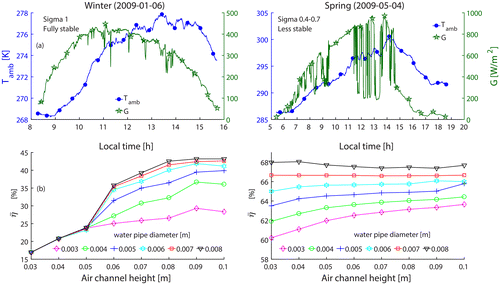
Figure 8. (a) Time variation of solar global irradiance and ambient air temperature for a more stable day with low cloudiness (15 July) and a fully stable day with overcast sky (13 October); (b) total daily efficiency, , for several values of the water pipe diameter (in m) and air channel height.
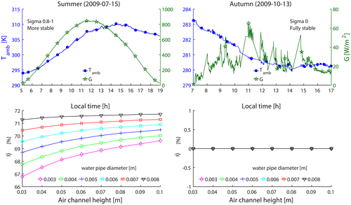
Figures (b) and (b) show the total thermal efficiency, for given values of water and air flow rates (0.12 and 0.04 kg/s, respectively) and inlet air temperature (ambient temperature). The values of water pipe diameter (Dpipe) and air channel high (L) range from 0.003 to 0.01 m and from 0.03 to 0.1 m, respectively.
The efficiency of the HSC system on 15 July is higher than that on 6 January, 4 May and 13 October, respectively. Also, the efficiency of the HSC system on 4 May is higher than the efficiency on 6 January, 4 May and 13 October, respectively, for the same values of Dpipe and L. However, the difference between the total efficiency on 15 July and 4 May, respectively, is rather small. Detailed results for other days of Table are presented in Figures A12–A22 in ESM.
Generally, the system efficiency increases by increasing the water pipe diameter and the air channel height. This result is a consequence of the complicated interplay between different effects that the size of the water pipe diameter and air channel height has on various quantities entering the useful heat defining the efficiency (see Equation (Equation27(27) )), such as convection heat transfer coefficients, water and air speeds, heat transfer surface areas, Reynolds and Nusselt numbers. A special case is the sunny day 6 January, when the atmospheric temperature is low and the inlet air temperature is low as well (Figure ). The efficiency curves are quite close to each other for air channel heights between 0.03 and 0.05 m. Another special case is the overcast sky day of 13 October (Figure ). Since the incoming irradiance is very low, the water pump does not operate in that day. Therefore, the efficiency is zero all the day long.
Dependence of HSC system performance on storage tank volume
The sun is effectively shining about 5–6 h per day. However, heating and hot water demand is needed all the day long. Therefore, a thermal energy storage system is useful. Simulations were made for HSC systems with different storage tank capacities and the effect on HSC systems efficiency has been studied.
Figure (a) shows the efficiency of the HSC system for 26 July 2009. A constant air mass flow rate 0.06 kg/s (0.033 kg/(s m2)) has been assumed. The efficiency increases when the volume of the storage tank increases. When the storage tank volume is 500L, the efficiency of the collector is the highest, while it becomes the lowest when the storage tank volume is 300 L. This agrees with results of (Buonomano et al. Citation2014, 298; Hasan Citation1997, 853). The maximum and minimum average daily efficiency obtained for the HSC system were 45.8% and 43.7%, for storage tank volumes of 500 L and 300 L, respectively. Figure (b) shows the relation between the storage tank water temperature at the end of the day and the tank volume. The highest temperature of the water in the tank was obtained for a volume of 300 L, which agrees with the results reported by Buonomano et al. (Citation2014, 298).
Figure 9. Effect of storage tank volume on efficiency and water temperature for different water mass flow rate on 26 July 2009. A constant air mass flow rate 0.06 kg/s (0.033 kg/(s m2)) has been considered.
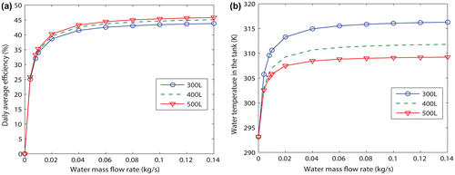
A few comments follow. Both the daily averaged efficiency and the water temperature increase by increasing the mass flow rate. The fact that the water temperature is lower for higher volume of the tank can be explained by the fact that the same amount of thermal energy supplied by the collectors is warming a larger amount of water in the tank. Thus, the tank water temperature would be smaller.
Conclusions
The objective of this paper is to estimate the performance of a HSC system for water and air heating during days with different stability of the radiative regime. A theoretical model for HSC System operation has been developed. An on–off control method has been adopted for pump operation. A fully mixed water storage tank has been considered. The model has been validated against data obtained by measurements.
A large meteorological database with measurements from Timisoara (Romania, Eastern Europe) has been prepared. It contains data from 29 different days of year 2009, covering all four seasons. The days selected are stratified according to their daily relative sunshine in clear sky days, overcast sky days, low cloudiness, medium cloudiness and high cloudiness days, respectively. These days are more stable or less stable from the point of view of the radiative regime.
Simulations of HSC system operation have been performed and analysed in different weather conditions. The main conclusions follow.
| (1) | The HSCs, with two fluids, are more effective than single-fluid collectors since they decrease the cost and required space per unit of collected solar energy. | ||||
| (2) | The mass flow rate of the working fluids (water and air) is one of the most important parameters affecting the performance of the HSC system. A higher water flow rate generally enhances the thermal efficiency of the HSC system, but the enhancement became significantly less at a higher air flow rate. The maximum thermal efficiency of the HSC system is obtained in winter and summer, when the water mass flow rate per unit area of collector is 0.0658 kg/(s m2), while in spring and autumn the maximum efficiency is obtained for 0.011 and 0.022 kg/(s m2), respectively. | ||||
| (3) | The pump operation may become rather unstable in days with less stable radiative regime. Positive but small values are recommended for the difference between the fluid temperature at solar collectors exit and the water temperature in the tank, when acting as a condition for starting and stopping pump operation (for instance, 0.2 °C and 3 °C, respectively). | ||||
| (4) | The thermal efficiency of the HSC system depends on the state of the sky. This dependence is secondary to the dependence on season. | ||||
| (5) | Generally, the system efficiency is decreasing when the air channel height and the water pipe diameter decrease. | ||||
| (6) | The efficiency of an HSC system can be increased by increasing the volume of the water storage tank. | ||||
Disclosure statement
No potential conflict of interest was reported by the authors.
Notes on contributors
Qahtan Adnan Abed (born in Baghdad, Iraq 1977) is an assistant professor in Technical Engineering College of Najaf (http://www.etcn.edu.iq/).
Al-furat Al-awsat Technical University (http://atu.edu.iq/). His mainstream scientific contributions consist of more than 20 papers and one book chapter in title Some Solar Energy Technologies and Applications. He is review in different international journals.
Viorel Badescu (born in Bughea de Jos, Arges, Romania, 24 September 1953) is a professor of Engineering Thermodynamics and affiliated with Candida Oancea Institute at Polytechnic University of Bucharest. His mainstream scientific contributions consist of more than 250 papers and several books related to statistical physics and thermodynamics, the physics of semiconductors, and various aspects of terrestrial and space solar energy applications. Also, he has theorized on present-day Mars meteorology and Mars terraforming and on several macro engineering projects. He is a reviewer or associate editor of more than 50 international journals and member of eight scientific societies including the International Solar Energy Society and the European Astronomical Society. He received four awards including the Romanian Academy Prize for Physics in 1979. He is corresponding member of the Romanian Academy.
Iuliana Soriga, PhD, works as an assistant lecturer at Politehnica University of Bucharest, Romania. Her research and professional experience is centered on renewable energy (solar thermal collectors, passive house, radiative regime), computational simulation and optimization of solar systems, and refrigeration systems. Previous publications have appeared in Energy Conversion and Management, Energy, Renewable Energy, Journal of Non-Equilibrium Thermodynamics and others.
Supplemental data
Supplemental data for this article can be accessed here. https://doi.org/10.1080/19397038.2017.1333542.
ESM.doc
Download MS Word (939.5 KB)Acknowledgements
The authors thank Dr. Marius Paulescu (West University of Timisoara, Romania) for providing the meteorological and radiometric database.
Related Research Data
References
- Andoh, H., P. Gbaha, B. Koua, P. Koffi, and S. Touré. 2010. “Thermal Performance Study of a Solar Collector Using a Natural Vegetable Fiber, Coconut Coir, as Heat Insulation.” Energy for Sustainable Development 14: 297–301.10.1016/j.esd.2010.09.006
- Assari, M. R., H. Basirat Tabrizi, and I. Jafari. 2011. “Experimental and Theoretical Investigation of Dual Purpose Solar Collector.” Solar Energy 85: 601–608.10.1016/j.solener.2011.01.006
- Azad, E. 2012. “Design, Installation and Operation of a Solar Thermal Public Bath in Eastern Iran.” Energy for Sustainable Development 16: 68–73.10.1016/j.esd.2011.10.006
- Badescu, V. 1999. “Correlations to Estimate Monthly Mean Daily Solar Global Irradiation: Application to Romania.” Energy 24: 883–893.10.1016/S0360-5442(99)00027-4
- Badescu, V. 2002. “A New Kind of Cloudy Sky Model to Compute Instantaneous Values of Diffuse and Global Solar Irradiance.” Theoretical and Applied Climatology 72: 127–136.10.1007/s007040200017
- Badescu, V. 2008. “Optimal Control of Flow in Solar Collector Systems with Fully Mixed Water Storage Tanks.” Energy Conversion and Management 49: 169–184.10.1016/j.enconman.2007.06.022
- Badescu, V., P. T. Landsberg, and A. De Vos. 1997. “Statistical Thermodynamic Foundation for Photovoltaic and Photothermal Conversion III: Application to Hybrid Solar Converters.” Journal of Applied Physics 81: 3692–3699.10.1063/1.365490
- Badescu, V., and N. Rotar. 2012. “Implementation of the German Passivhaus Concept in Southeast Europe: Considerations for Romania.” Journal of Energy Engineering 138: 146–162.10.1061/(ASCE)EY.1943-7897.0000066
- Badescu, V., and E. Zamfir. 1999. “Degree-days, Degree-hours and Ambient Temperature Bin Data from Monthly-average Temperatures (Romania).” Energy Conversion and Management 40: 885–900.10.1016/S0196-8904(98)00148-4
- Baehr, D., and K. Stephan. 2006. Heat Transfer. 2nd ed. Berlin: Springer.
- Bales, C., and T. Persson. 2003. “External DHW Units for Solar Combisystems.” Solar Energy 74: 193–204.10.1016/S0038-092X(03)00158-0
- Buonomano, A., F. Calise, and G. Ferruzzi. 2013. “Thermoeconomic Analysis of Storage Systems for Solar Heating And Cooling Systems: A Comparison between Variable-volume And Fixed-volume Tanks.” Energy 59: 600–616.10.1016/j.energy.2013.06.063
- Buonomano, A., F. Calise, G. Ferruzzi, and L. Vanoli. 2014. “Variable-volume Storage Systems for Solar Heating and Cooling System: A Case Study for Different Italian Climates.” Energy Procedia 48: 290–299.10.1016/j.egypro.2014.02.034
- Csordas, G. F., A. Brunger, K. Hollands, and M. Lightstone. 1992. “Plume Entrainment Effects in Solar Domestic Hot Water Systems Employing Variable-flow-rate Control Strategies.” Solar Energy 49: 497–505.10.1016/0038-092X(92)90158-7
- Duffie, J., and W. Beckman. 1991. Solar Engineering of Thermal Processes. New York: Wiley.
- Ghassan, M., A. Mohannad, and K. Atif. 2011. “Solar Adsorption Refrigeration (SAR) System Modeling.” Energy Efficiency 4: 247–256.
- Guarracino, I., A. Mellor, Nicholas J. Ekins-Daukes, and Christos N. Markides. 2016. “Dynamic Coupled Thermal-and-electrical Modelling of Sheet-and-tube Hybrid Photovoltaic/Thermal (PVT) Collectors.” Applied Thermal Engineering 101: 778–795.10.1016/j.applthermaleng.2016.02.056
- Hamed, M., A. Fellah, and A. Ben Brahim. 2014. “Parametric Sensitivity Studies on the Performance of a Flat Plate Solar Collector in Transient Behavior.” Energy Conversion and Management 78: 938–947.10.1016/j.enconman.2013.09.044
- Hasan, A. 1997. “Thermosyphon Solar Water Heaters: Effect of Storage Tank Volume and Configuration on Efficiency.” Energy Conversion and Management 38: 847–854.10.1016/S0196-8904(96)00099-4
- Herrando, M., and C. N. Markides. 2016. “Hybrid PV and Solar-thermal Systems for Domestic Heat and Power Provision in the UK: Techno-economic Considerations.” Applied Energy 161: 512–532.10.1016/j.apenergy.2015.09.025
- Herrando, M., C. N. Markides, and K. Hellgardt. 2014. “A UK-based Assessment of Hybrid PV and Solar-thermal Systems for Domestic Heating and Power: System Performance.” Applied Energy 122: 288–309.10.1016/j.apenergy.2014.01.061
- Ihaddadene, R., N. Ihaddadene, M. Bey, and F. Z. Hamdibacha. 2014. “The Effects of Volumetric Flow Rate and Inclination Angle on the Performance of a Solar Thermal Collector.” Energy Conversion and Management 78: 931–937.
- Jafari, I., A. Ershadi, E. Najafpour, and N. Hedayat. 2011. “Energy and Exergy Analysis of Dual Purpose Solar Collector.” World Academy of Science, Engineering and Technology 57: 259–261.
- Jaisankar, S., T. Radhakrishnan, and K. Sheeba. 2009. “Experimental Studies on Heat Transfer and Friction Factor Characteristics of Thermosyphon Solar Water Heater System Fitted with Spacer at the Trailing Edge of Twisted Tapes.” Applied Thermal Engineering 29: 1224–1231.10.1016/j.applthermaleng.2008.06.009
- Ji, J., Chenglong Luo, Tin-Tai Chow, Wei Sun, and Wei He. 2011. “Thermal Characteristics of a Building-integrated Dual-function Solar Collector in Water Heating Mode with Natural Circulation.” Energy 36: 566–574.10.1016/j.energy.2010.10.004
- Kalogirou, S. 2009. Solar Energy Engineering: Processes and Systems. California: Elsevier.
- Kays, W., M. Crawford, and B. Weigand. 2005. Convective Heat and Mass Transfer. 4th ed. Singapore: McGraw-Hill.
- Khamis, M. 2013. “Thermal Analysis of Novel Minichannel-based Solar Flat-plate Collector.” Energy 60: 333–343.10.1016/j.energy.2013.08.013
- Knudsen, S. 2002. “Consumers’ Influence on the Thermal Performance of Small SDHW Systems—Theoretical Investigations.” Solar Energy 73: 33–42.10.1016/S0038-092X(02)00018-X
- Li, D. H W, and J. Lam. 2011. “An Analysis of Climatic Parameters and Sky Condition Classification.” Building and Environment 36: 435–445.
- Ma, J., W. Sun, J. Ji, Y. Zhang, A. Zhang, and W. Fan. 2011. “Experimental and Theoretical Study of the Efficiency of a Dual-function Solar Collector.” Applied Thermal Engineering 31: 1751–1756.10.1016/j.applthermaleng.2011.02.019
- Malhotra, A., H. Garg, and A. Palit. 1981. “Heat Loss Calculation of Flat Plat Solar Collectors.” Journal of Thermal Energy 2: 59–62.
- Menzies, G. F., and Y. Roderick. 2010. “Energy and Carbon Impact Analysis of a Solar Thermal Collector System.” International Journal of Sustainable Engineering 3: 9–16.10.1080/19397030903362869
- Mohajer, A., O. Nematollahi, M. Joybari, S. Hashemi, and M. Assari. 2013. “Experimental Investigation of a Hybrid Solar Drier and Water Heater System.” Energy Conversion and Management 76: 935–944.10.1016/j.enconman.2013.08.047
- Nematollahi, O., P. Alamdari, and M. Assari. 2014. “Experimental Investigation of a Dual Purpose Solar Heating System.” Energy Conversion and Management 78: 359–366.10.1016/j.enconman.2013.10.046
- Panna, L., S. Deshpandey, and P. Jena. 2015. “Thermal Performance of Packed Bed Heat Storage System for Solar Air Heaters.” Energy for Sustainable Development 29: 112–117.
- Paulescu, M., and V. Badescu. 2011. “New Approach to Measure the Stability of the Solar Radiative Regime.” Theoretical and Applied Climatology 103: 459–470.10.1007/s00704-010-0312-9
- Picón-Núñez, M., G. Martínez-Rodríguez, and A. Fuentes-Silva. 2014. “Design of Solar Collector Networks for Industrial Applications.” Applied Thermal Engineering 70: 1238–1245.10.1016/j.applthermaleng.2014.05.005
- Pottler, K., C. Sippel, A. Beck, and J. Fricke. 1999. “Optimized Finned Absorber Geometries for Solar Air Heating Collectors.” Solar Energy 67: 35–52.10.1016/S0038-092X(00)00036-0
- Prapas, D. E., I. Veliannis, A. Evangelopoulos, and B. A. Sotiropoulos. 1995. “Large DHW Solar Systems with Distributed Storage Tanks.” Solar Energy 55 (3): 175–184.10.1016/0038-092X(95)00042-P
- Rangarajan, S., and M. Swaminathan. 1984. “Computation of Solar Radiation from Observations of Cloud Cover.” Solar Energy 32: 553–556.10.1016/0038-092X(84)90270-6
- Razika, I., I. Nabila, B. Madani, and H. Zohra. 2014. “The Effects of Volumetric Flow Rate and Inclination Angle on the Performance of a Solar Thermal Collector.” Energy Conversion and Management 78: 931–937.10.1016/j.enconman.2013.09.051
- Schnieders, J. 1997. “Comparison of the Energy Yield Predictions of Stationary and Dynamic Solar Collector Models and the Models’ Accuracy in the Description of a Vacuum Tube Collector.” Solar Energy 61: 179–190.10.1016/S0038-092X(97)00036-4
- Sekar, M., M. Sakthivel, S. Satheesh, and C. Ramesh. 2012. “Effect of Solar Intensity on Efficiency of the Convection Solar Air Heater.” Journal of Renewable and Sustainable Energy 4: 1–6.
- Solar Radiation Monitoring Station of the West University of Timisoara, Romania. Accessed September 2014. http://solar.physics.uvt.ro/srms
- Varghese, P., and P. G. Jino. 2016. “Experimental Study on Cooling of Solar Collectors Using Air–Water Mixture.” Energy Procedia 91: 303–311.
- Venkatesh, R., and W. Christraj. 2014. “Experimental Investigation of Multipurpose Solar Heating System.” Journal of Energy Engineering 141: 1–10. doi:10.1061/(ASCE)EY.1943-7897.0000166.
- Venu, A., and P. Arun. 2013. “Simulation Studies on Porous Medium Integrated Dual Purpose Solar Collector.” International Journal of Renewable Energy Research 3: 114–120.
- Winterton, R. 1998. “Where Did the Dittus and Boelter Equation Come from?” International Journal of Heat and Mass Transfer 41: 809–810.10.1016/S0017-9310(97)00177-4
- World Meteorological Organization. 2014. “Guide to Meteorological Instruments and Methods of Observation.” WMO-No.8. http://www.wmo.int/.
- Yan, G., Z. Qunli, F. Rui, L. Xinxing, and Y. Yong. 2013. “Effects of Thermal Mass and Flow Rate on Forced-circulation Solar Hot-water System: Comparison of Water-in-glass and U-pipe Evacuated-tube Solar Collectors.” Solar Energy 98: 290–301.
- Ziqian, C., F. Simon, P. Bengt, F. Jianhua, and A. Elsa. 2012. “Efficiencies of Flat Plate Solar Collectors at Different Flow Rates.” Energy Procedia 30: 65–72.