Abstract
A number of tools and software systems have been developed in order to reduce the time for the design and manufacturing of industrial products. Nowadays, virtual modelling by Computer Aided Design (CAD) systems and process simulation by the application of Finite Element Method (FEM) software is a standard routine in order to compress product design activities and to achieve the optimal solution before producing any real components. These developments provided not only a reduction in the time to market but a higher complexity of the project and an improved quality of the industrial products. With the aim to further improve the sustainability of this activity, the implementation of a tool that adds automatic operations into the design activity is demonstrated. This software can interact with any CAD and helps designers when the object dimension and shape can be affected by limits and constraints deriving from different features and targets, such as the spatial collocation of the component and the interaction with other limiting items, for examples the material and the manufacturing issues. The concept was developed into the software SFIDA (Sailplane Fuselage Integrated Design Application) that is a first attempt to automatically manage multiple relations and optimise their combination.
1. Introduction
The first official definition of sustainability appeared in 1987 in a report entitled ‘Our Common Future’ by the World Commission on Environment and Development (WCED). According to the WCED document, sustainability means meeting the needs of the present without compromising the ability of future generations to meet their own needs (WCED Citation1987; Tamborrini Citation2009).
In the last two decades, sustainability has become relevant to scholars, experts and citizens in general. People’s concern about the future of our planet is increasing and several publications and books, such as the famous best-seller ‘Blue Economy’ (Pauli Citation2010), have contributed to spread around awareness about this issue.
Traditionally, sustainability has been identified in the capability of using renewable materials, saving energy, reducing pollution, etc. focusing on its environmental dimension. The introduction of the Three Bottom line: Environment, Economy, Society implied the addition of two further dimensions of sustainability, which are connected to economic and social factors (WCED Citation1987).
Industry is a domain where all these three dimensions are significant and many researches focus possible improvements of sustainability in the industrial production, analysing environmental, economic and social issues.
In particular, the optimisation of the industrial product development process is fundamental in order to limit negative effects on the environment, reduce costs and improve people’s quality of life. The sustainable social dimension here does not only refer to the consumers and to the users of the product but also to the workers who contribute to its production.
Focusing the product design, a remarkable point is the reduction of the time needed to identify the best correct solution to be manufactured. To reach this aim, the design and the industrialisation of any good should possibly be developed together using the so-called Concurrent Engineering (CE) approach. CE helps to prevent from becoming aware of possible mistakes in design only once the product has already reached an advanced phase of its development, when a prototype has already been manufactured and the modification of the product implies long times and relevant costs.
Designers must contribute to increase the number of alternatives, which means strategies of solution to the problems, technically and economically practicable by consumers/users (Elkington Citation1997). According to the above-described approach, designers must have tools that support them in the ideation of products, taking in consideration several factors related to the manufacturing phase since the concept one. They need to be able to imagine several possible solutions, whose feasibility can be guaranteed though the correct use of a tool combining possible materials and manufacturing technologies without wasting time in exploring unfeasible possibilities. A tool like this can increase the sustainability of the product and of its production process. In fact, the possibility to make the preliminary analysis of the critical issues of the project, including the ones related to sustainability, helps to reduce the number of solutions to be considered and decreases the need of modifications in a later stage of the product development. Due to a number of constrains that are usually related to the connection between materials and manufacturing processes, adjustments and corrections of a project at an advanced stage of the development are difficult – in some cases not feasible any more – and very expensive (Swift and Brown Citation2003).
A number of research papers dealt with the discussed topic: a novel methodology for enabling Multidisciplinary Design Optimisation (MDO) of complex engineering products is proposed by Amadori et al. (Citation2012) and the concept of High Level Computer Aided Design (HLCAD) templates was proposed and discussed. The proposed applications aim at the automation of the design of transport aircrafts, industrial robots and micro air vehicles.
MDO can be defined as an assemblage of methods, procedures and algorithms for finding the best design solution by taking into account a number of criteria and constraints belonging to different disciplines (Sobieszczanski-Sobieski, Morris, and van Tooren Citation2015). Engineering problems are generally characterised by a number of often-conflicting and incommensurable objectives (Sobieszczanski-Sobieski and Haftka Citation1997). In particular, aircraft design deals with a wide set of parameters that affect the features of the resulting product therefore aeronautics has been one of the main fields of development for these mentioned techniques (Breitkopf and Coelho Citation2013).
Most applications of the MDO technique realise the task to build a closed loop in the design chain that acts on the input parameters to fulfil requirements concerning the final solution (Martins and Lambe Citation2013). This result can be achieved by combining CAD and CAE with the aim to measure and optimise the effects of variations in the design parameters (Chan-gi and Wesley Citation2009).
When applying MDO to preliminary design (Kroo et al. Citation1994), the aim is mainly to guide the designer in important choices and thus to reduce the amount of changes during the product development.
Another innovative methodology for design optimisation was proposed in (Byrne et al. Citation2014) by the implementation of a design generation tool that is combined with an analysis software and an evolutionary algorithm. The evolutionary algorithm was used to generate a range of model of aircrafts by two optimising rules (maximise the lift and reduce the drag) and a constraint (keep the framework of the original design). The proposed approach allows automatically an optimisation of the design procedure. In Hsiao and Tsai (Citation2005), a method which enables an automatic product form search or product image evaluation by means of a fuzzy neural network and genetic algorithms was proposed. A feature-based hierarchical Computer Aided Design (CAD) model was constructed in order to facilitate the automatic generation of new product forms.
The concept was implemented in a case study with the aim to improve the design of the fuselage for a single-seat glider by including numerous automatic tools for taking into account a number of boundary conditions and constraints by including pilot needs of comfort and safety. The method can be, theoretically, easily applied and extended to families of industrial products.
In the present paper, an application for the preliminary design of the fuselage for a single-seat glider is presented, aiming to provide assistance to the designer during the conceptual stage of the project development by automatising some drawing operations. Then, three output parameters of the design process have been selected in relationship with a number of issues of the project, including sustainability; a relation among design parameters and the selected expected performances has been obtained in order to propose a possible decisional tool.
The developed framework of automated design can be also considered as a starting point for the integration with automated MDO techniques in the following phases of the detailed design of the fuselage.
The final aim is to give more freedom to the designer, who will be able to focus on the comparison of a high number of different solutions in a short time and to simplify the research of the best solution. Designers will be able to dedicate to the creative aspects without being fully engaged in the design implementation.
2. The general concept
The software SFIDA (Sailplane Fuselage Integrated Design Application) is a Knowledge-Based Engineering tool developed in order to assist and guide through the design of fuselages for mono-seat civil sailplanes. The design process of the part has been investigated in order to point out some key aspects involved in the definition of the shape. Nonetheless, the relations and interactions between different aspects have been considered to define an effective sequence of operation and to ensure the model to be consistent when some modifications are operated by the user. To reach this aim, a number of parameters have been considered in several different fields:
| • | Ergonomic | ||||
| • | Materials and Manufacturing | ||||
| • | Functionality | ||||
| • | Safety | ||||
These parameters, according to their role in design, have been considered as variables, constraints or measured in order to check the validity and performances of the described solution. The aim of SFIDA is to manage the network of relations among these parameters, leaving the opportunity to the designer to focus on the decision-making process, delegating to the software the calculation of indirectly defined parameters and the resolution of various design conflicts.
In the following paragraphs, some features of the software system will be analysed in order to better explain how the design requirements are managed to quickly generate consistent preliminary models.
As a second step of the process, a few output parameters from the design process will be selected basing on the expected performances, including sustainability aspects. Finally, an effective decisional tool has been defined based on a relation between the design parameters and the selected expected performances.
2.1. The modelling of the pilot posture
The starting point of the proposed concept design begins with the pilot posture. Several requirements must be satisfied to find a suitable solution for the posture of the person inside the sailplane. As the first simple example, the space inside the cockpit (that is directly governed by the geometry of the fuselage) has to allow the pilot comfort and his movements to properly manage all the commands that are used to drive the aircraft. On the other hand, the dimensions of the fuselage have to be minimised due to the necessity to achieve the aerodynamic efficiency of the sailplane, which is of course a functional primary aim.
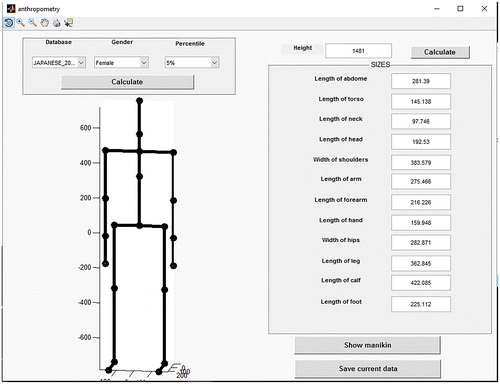
A comfortable posture is a key feature to determinate the quality of a sailplane, even affecting the safety of the flight. The relation between posture and safety is also more evident if considering the kinematics of the body in case of crash. According to this important consideration, the definition of the human model is therefore a first step in the sequence of activities that are the purpose of the proposed software architecture. Figure displays the panel that helps in order to set the anthropometry of the pilot.
Different methods can be used to perform this definition. Using the combo box in the up left of the window, it is possible to use as reference for many anthropometric databases assigning the geographical zone, the gender and the percentile. This selection automatically set sizes of different body segments of the pilot. Otherwise, a relational model can be adopted: in this case the user types in the whole height of the person, on the base of which all the measurements are calculated. Finally, it is possible to manually type in values of different sizes to use more accurate data. This method can be also combined to previous ones, correcting values calculated according to the will of design.
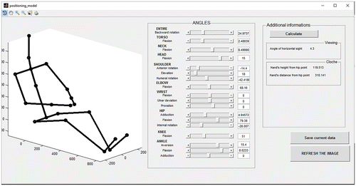
Figure shows the panel that can be used in the application to set the posture assigned to the human model for piloting.
This architecture allows to set variable parameters (i.e. human sizes) in different ways, providing both a quick way to adapt design to different subjects and the opportunity to use very specific data, according to the principles previously exposed.
The posture of the pilot is set assigning the angular values for different articulation as well as the inclination of the whole body in reference to the vertical axis. According to the application, not all the articulations are managed; as an example, being the posture supposed to be symmetrical, only one side is considered and the rotation of the torso is not allowed. The value of each angle can only be set inside a defined range. In fact, constraints given by safety and anatomical issues are included in the calculation of boundaries related to each parameter. This window also provides an example of quick check and measurement tools included in the software. In fact, on the panel in the upper right of the screen, some parameters directly related to the defined posture (such as the angle of the sight referring to the horizontal or the height of the hands) are computed and displayed to the user. This approach allows some preliminary considerations on the solution while defining it, advancing the decision-making.
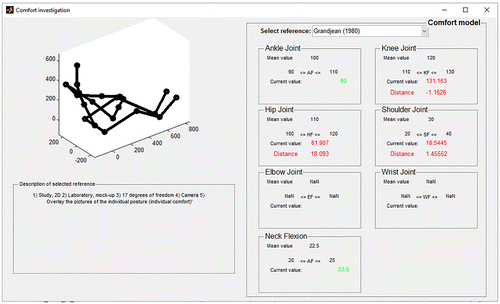
A more specific analysis tool, as displayed in the window of the Figure , have been dedicated to the pilot posture with the aim to investigate and provide the level of comfort by exploitation of implemented algorithms.
In this case, an analysis is performed with reference to several comfort models that are described in the scientific literature that was mainly developed for the automotive industrial sector and then applied to the aeronautical one. By choosing one of these models in the combo box on the top right side of the window, the posture is automatically analysed and compared, so that joint angles considered uncomfortable are displayed in red, while the other good ones are represented in green colour. This visual method allows designers to make quick comparisons with other concurrent models in the shortest time and to decide if virtually tested modifications of the defined pilot posture are necessary or required.
Furthermore, a brief description of the selected reference is provided in the bottom left side of the screen in order to help less skilled users in choosing the correct model.
2.2. The shape of the fuselage
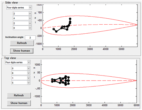
The shape of the fuselage of the sailplane is designed trying to reach the best aerodynamic performances during flight. Therefore, the first step in the definition of the streamline is the selection of an aerofoil based on 4 or 5-digit series that were proposed by the National Advisory Committee for Aeronautics (NACA). Two aerofoils are defined for the top and the side view, as displayed in Figure .
According to the NACA definition, not all the combinations of digits correspond to a streamline: therefore, the software automatically limits the possible choices to assist the designer during the definition.
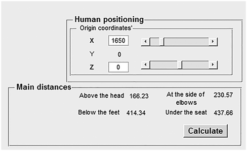
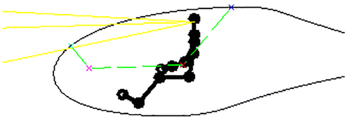
As previously mentioned, the frontal surface of the aircraft has to be contained in order to improve the performances of flight; the main constraint, as obvious, is the necessity to house the pilot and the control instruments inside the cockpit. Due to this prerequisite, the positioning of the pilot inside the aerofoil is leaded in parallel with the one of the aerofoils using the same window. A simplified representation of the human model can be included in the representation (as in Figure ) in order to provide an immediate visual feedback about the interaction of these two elements.
This ‘first level check’ is integrated by a more accurate calculation of some fundamental distances between the pilot and the fuselage. The panel displayed in the Figure shows the automatically performed calculation by the system.
To complete the streamline, the two defined profiles have to be interpolated by transversal sections, that can be defined inside the software for different values of the abscissa using different conic sections. The shape of transversal sections is automatically calculated, allowing the designer to have a quick three-dimensional representation of the streamline.
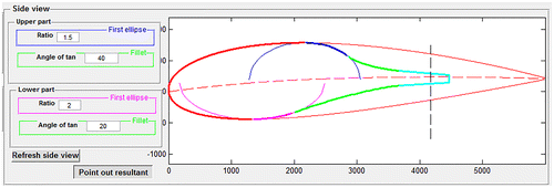
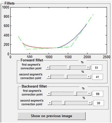
To complete the shape, a preliminary model of the tail is required in order to define how this part is connected to the aerofoils assigned to the front part. The relative position of the tail is therefore assigned, as well as the percentage of tail to be included in the fuselage. Then, using the same window, two semi-ellipses are inscribed in the aerofoils in their maximum thickness point and connected with an elliptical fillet to the straight zone as in Figure .
In the image above, the resulting profile of the fuselage is marked with different colours that are used for putting in evidence different parts of the geometry. In order to allow a quick definition of the shape, the parameters to be managed have been reduced to the ratio between semi-axes of the ellipse and angle of tangency between the elliptical fillet and the ellipse itself. This has been considered the most intuitive way for designer to manage such a profile; the background calculation of all the points of the resulting geometry allows to have a quick representation of the solution.
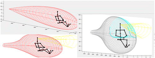
In this step, and in previous ones as well, a three-dimensional preview of the cockpit shape can be used in order to get a further check of the solution during its definition. Figure shows these visual tools.
2.3. Additional features of the fuselage
As obvious, in order to complete the fuselage, some additional features have to be defined; as a first example, only the external shape has been considered so far.
In order to investigate the thickness of the part, many different considerations have to be done on the structure of the fuselage. In fact, the thickness is directly related to the materials employed for the construction and, more accurately, with the layers of the laminated composite. In order to manage this aspect, it is possible to define up to eight plies using the most commonly used materials employed in this field, that are:
| • | Carbon fibres | ||||
| • | Glass fibres | ||||
| • | Aramid fibres | ||||
| • | Polyester | ||||
| • | Polyurethane | ||||
As it can be seen, some of these materials are isotropic while some other are not. In case of non-isotropic materials, the software demand to the user the indication of the main orientation of the ply; this information can afterwards be transferred to other digital environments, such as the one employed for structural simulations.
The sequence of plies is itself subjected to many different constraints related to both functional and manufacturing requirements. As an example, each ply made by carbon or glass fibres should have an inner layer in Kevlar (i.e. Aramid fibres) to protect the pilot by sharp edges in case of crash. A manufacturing driven example can be provided by the external layer, where the use of Polyurethane (PUR) is discouraged because it can lead to the formation of droplets when in contact with the release agent of the mould.
To ensure a consistence stacking sequence, a check tool (shown in Figure ) is provided to quickly point out eventual issues in the purposed solution.
Another key aspect to complete the design on the fuselage, is the definition of the window in the canopy; this is preliminary managed assigning the coordinates of a polygon on the side view, as displayed in Figure . The shape of the canopy is then completed with elliptical fillets using the panel in Figure .
It is worth to notice how the used parameters in order to define the elliptical fillets are deeply different from the previous case (that is the tail joining). In fact, in this panel the user indicates the percentage of the polygon side where ends of the fillet are placed. This choice of handling parameters has a deep meaning; in fact, it better reflects a design issue, that is the trade-off between the viewing field and the material resistance in case of crashes, that has to be managed when defining the shape of the canopy. A check tool is also provided with the calculation of distance between the pilot visual field (defined in previous steps) and the windows in the canopy in the fore part of the fuselage. Once again, this aspect can be deeply investigated using a three-dimensional preview that includes all the elements of the design.
2.4. Output and a proposal of a decisional tool
Once all the parameters have been defined, the user can quickly and directly export the automatically generated models to the CAD environment. The exported models include the fuselage, the canopy, the pilot (in the predefined posture) and the assembly of all these elements. The automatically generated CAD format allows to employ this preliminary design to operate further modifications for the next step of detailed design.
The way in which data are managed by the SFIDA, as well as the digital information exchange with the CAD environment, avoid the onset of regeneration errors in the CAD model if or when design is changed. In fact, both internal and external surfaces are computed inside of SFIDA, ensuring the manifold condition for every value of thickness and shape of streamline. Surfaces are then employed to build the solids of the parts in Boundary Representation (B-Rep) in the CAD environment. This approach ensures the consistency of the model, that in most of the cases cannot be obtained with different modelling techniques, such as the offsetting of the surfaces or the shelling of the filled solid.
The high number of choices operated in the software, leads to a wide range of possible models that can be obtained. For example, the market proposes numerous solutions for this component by taking into account possible different postures of the pilot (Figure ).
Figure 11. Three selected models obtained quickly and directly through the use of SFIDA that show different postures of the pilot.

The mentioned generated models can also be used to perform preliminary analysis on a set of selected solutions or analysis by Computer Aided Engineering systems, such as Computational Fluid Dynamics (CFD) or structural ones.
With the aim to show a possible decisional tool based on the proposed systems, a preliminary analysis was performed, by considering the following output of the SFIDA:
| • | The ergonomic parameters related to the postures of pilots (Tilley and Dreyfuss Associates Citation2002). | ||||
| • | The maximum transversal area of the fuselage in the direction of flight, S, as a parameter that is in relationship with the drag force exerted by the fluid around the sailplane during the flight (Thomas and Milgram Citation1999; FAA Citation2008). | ||||
| • | The volume, V, of the composite material used to realise the fuselage (by considering a constant thickness of walls equal to 8 mm) that is in relationship with the weight of the sailplane (Thomas and Milgram Citation1999; FAA Citation2008). | ||||
Table shows the achieved ergonomic parameters that were extracted by the three models already displayed in Figure , which differ for the posture of the pilot. Each column of the table reports estimated values for each relevant angle related to the pilot comfort.
Table 1. Joint angles of the pilot’s posture, transversal surface and material volume.
Table shows a data elaboration of the previous ergonomic values in order to calculate an Average Fuzzy Comfort (AFC) index, which was obtained as the average value of the normalised ergonomic parameters. The normalisation was realised by a triangular membership function, according to (Pedrycz Citation1994).
Table 2. Comfort estimation of the pilot’s posture based on the proposed tool output.
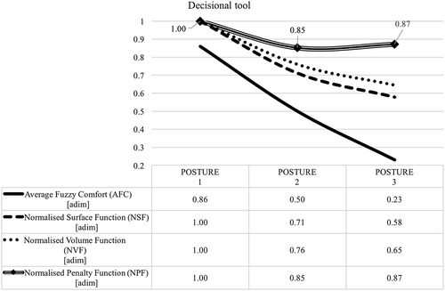
As a decisional tool based upon the three selected parameters, a Normalised Penalty Function NPF(x) based on the penalty function f(x) is here proposed (Equation Equation1(a) and (b)):(1a)
(1b)
where NSF, NVF are Normalised Surface and Normalised Volume Functions, respectively; wAFC, wS, wV are weights for the AFC, the NSF for the transversal surface and the NVF of the composite material, respectively; f(x)max, Smax, Vmax are the maximum value of the penalty function, the mentioned surface and volume in the examined range of solutions, respectively. The variable x represents the examined solution. It is worth to mention that the AFC has an opposite effect on the penalty function in comparison with the other two selected parameters.
Figure shows that the second posture is a trade-off between the need of an ergonomic solution and design by minimising the transversal area and the weight of the material. A number of preliminary analyses can be implemented and, in particular, sustainability can be taken into consideration in terms of the reduction of the material usage.
3. Conclusions
A new tool to support designers during the definition of a fuselage for a single-seat glider has been proposed. SFIDA is a Sailplane Fuselage Integrated Design Application that collects some of the key aspects of the design of the fuselage, manages its relations with the seat and the pilot of the aircraft by optimising the combination of the several parameters involved. SFIDA is connected and integrated to a CAD environment in order to use the mathematical description of geometries.
This concept that was successfully applied can increase the sustainability of the process of development of any industrial product, as it reduces the time that designers must dedicate to the CAD modelling and to the definition of the right composition of parameters, by implementing several solutions and optimising the interaction of the designed object with possible interacting elements.
In the examined case, the SFIDA is used to identify different models of fuselage, considering the reduced space of the cockpit where the person who has to drive the glider must fit. This tool can anyway have a wider use, being possible to apply this concept to different industrial product. A further aspect of this application connected to sustainability is the anthropomorphic relevance: the design of the fuselage and of the seat can be connected to the territory, in terms of the physical characteristics of the local population representing the target market. For instance, the average height and weight of a possible pilot who will enter the cockpit to drive the glider can be considered to choose the best solution.
The development of a decisional tool based upon selected parameters automatically calculated by the systems is showed in order to put in evidence the potential of this application in the preliminary design and the possibility to include parameters related to the sustainable issue.
Disclosure statement
No potential conflict of interest was reported by the authors.
Notes on contributors
Giampaolo Campana is an assistance professor (habil.) in the department of Industrial Engineering (DIN) of the University of Bologna since 2013. He is a researcher and assistant professor since 2005. He received his PhD in Engineering of Materials in 2004 by the University of Florence. His research activity concerns process modelling and optimisation, design for manufacturing and sustainability.
Mattia Mele is a PhD Student in the department of Industrial Engineering (DIN) of the University of Bologna. He is working within a project focused in the developing and application of Knowledge Based Engineering (KBE) systems in manufacturing.
Barbara Cimatti is a research associate in the department of Industrial Engineering (DIN) of the University of Bologna. She received her PhD in Mechanics of Materials and Technology Process by the University of Bologna and graduated with honours in Nuclear Engineering and later specialised in Management at UCLA (Los Angeles) and in Marketing at the University of Colorado, Boulder (Denver), USA. Her research activity concerns design for manufacturing and sustainability.
References
- Amadori, K., M. Tarkian, J. Oelvander, and P. Krus. 2012. “Flexible and Robust CAD Models for Design Automation.” Advanced Engineering Informatics 26 (2): 180–195. doi:10.1016/j.aei.2012.01.004.
- Breitkopf, P., and R. F. Coelho, eds. 2013. Multidisciplinary Design Optimization in Computational Mechanics. London, UK: Wiley-ISTE.
- Byrne, J., P. Cardiff, A. Brabazon, and M. O’Neill. 2014. “Evolving Parametric Aircraft Models for Design Exploration and Optimisation.” Neurocomputing 142: 39–47. doi:10.1016/j.neucom.2014.04.004.
- Chan-gi, P., and L. Wesley. 2009. “Multidisciplinary Design, Analysis, and Optimization Tool Development Using a Genetic Algorithm.” NASA/TM-2009-214645, NASA Dryden Flight Research Center, Edwards, California.
- Elkington, J. 1997. Cannibals with Forks: Triple Bottom Line of 21st Century Business. Oxford: Capstone Publishing.
- FAA (Federal Aviation Administration). 2008. Pilot’s Handbook of Aeronautical Knowledge. Oklahoma: U.S. Department of Transportation.
- Hsiao, S.-W., and H.-C. Tsai. 2005. “Applying a Hybrid Approach Based on Fuzzy Neural Network and Genetic Algorithm to Product Form Design.” International Journal of Industrial Ergonomics 35: 411–428. doi:10.1016/j.ergon.2004.10.007.
- Kroo, I., S. Altus, R. Braun, P. Gage, and I. Sobieski. 1994. “Multidisciplinary Optimization Methods for Aircraft Preliminary Design.” Proc. of the 5th Symposium on Multidisciplinary Analysis and Optimization, September7–9, 1994: 697–707.
- Martins, J. R. R. A., and A. B. Lambe. 2013. “Multidisciplinary Design Optimization: A Survey of Architectures.” AIAA Journal 51 (9): 2049–2075. doi:10.2514/1.J051895.10.2514/1.J051895
- Pauli, G. 2010. The Blue Economy: A Report of the Club of Rome. Taos, NM: Paradigm Publications.
- Pedrycz, W. 1994. “Why Triangular Membership Functions?” Fuzzy Sets and Systems 64 (1): 21–30. doi:10.1016/0165-0114(94)90003-5.
- Swift, K. G., and N. J. Brown. 2003. “Implementation Strategies for Design for Manufacture Methodologies.” Proceedings of the Institution of Mechanical Engineers, Part B: Journal of Engineering Manufacture 217 (6): 827–833.10.1243/09544050360673198
- Sobieszczanski-Sobieski, J., and R. T. Haftka. 1997. “Multidisciplinary Aerospace Design Optimization: Survey of Recent Developments.” Structural Optimization 14: 1–23, Springer-Verlag. doi: 10.1007/BF01197554.
- Sobieszczanski-Sobieski, J., A. Morris, and M. van Tooren. 2015. Multidisciplinary Design Optimization Supported by Knowledge Based Engineering. John Wiley & Sons.10.1002/9781118897072
- Tamborrini, P. M. 2009. Disegno Sostenibile: oggetti, sistemi e comportamenti [Sustainable Design: Products, Systems and Behaviours]. Milan: Electa.
- Thomas, F., and J. Milgram. 1999. Fundamental of Sailplane Design. College Park, MD: College Park Press.
- Tilley, A. R., and H. Dreyfuss Associates. 2002. The Measure of Man and Woman: Human Factors in Design. New York: John Wiley & Sons.
- WCED (World Commission on Environment and Development). 1987. Our Common Future: Report of the World Commission on Environment and Development. Oxford: Oxford University Press.

