Abstract
In this paper, heating and humidification of air for space have been carried out by using a phase change material (PCM)-based solar-powered desiccant wheel air conditioning (SPDWAC) in winter. The analysis of the setup has been done at different air flow rates. At low and high air flow rates, system has mean thermal coefficient of performance of 0.121 and 0.172, respectively, and mean exergy efficiency of 0.0787 and 0.0846, respectively. The mean thermal coefficient of performance of the system at high air flow rate (127.23 kg h-1) is 1.42 times the low air flow rate (63.62 kg h-1) and average exergy efficiency of the system at high air flow rate is 1.07 times the low air flow rate. It is observed that with an increase in air flow rate, efficiency of the evacuated tube solar air collector (ETSAC) increases. The average efficiency of the ETSAC at high air flow rate is 15.60%. The maximum average energy efficiency (17.80%) and exergy efficiency (17.08%) of the PCM storage system have been obtained at high air flow rate. The overall performance of the system showed that the use of PCM storage is feasible to run the system in winter during the hours of darkness.
1. Introduction
The regular sources, for example, coal, wood, oil and natural gas are broadly utilised for space heating and humidification. The wasteful burning of these fuels produces hurtful particles which are hazardous to the soundness of person. Hence, it exhibits that substitute strategy is required to beat the above-mentioned issues. The renewable energy resources such as solar energy is generally used for space heating and humidification. This original manuscript presents a desiccant humidifier system intended to produce heating and humidification of air amid off-sunshine hours. The phase change material (PCM)-based solar-powered desiccant wheel air conditioning (SPDWAC) system is utilised to fulfil the demand of heating and humidification in cold and dry climates. The demand for space heating is growing rapidly. Hence, it turns out to be extremely fundamental to focus in this area. Sarbu (Citation2014) concluded that for a situation of the conventional heat pump, the real disadvantage is that it requires high-grade energy. La et al. (Citation2011) suggested that in cold and dry weather, simply warming of space does not satisfy the comfort conditioning since relative humidity diminishes which prompt uneasiness condition. Henceforth to defeat these disadvantages, the DW-based air conditioning system is a substitute of the conventional heat pump. Charoensupaya and Worek (Citation1988) analysed the impact of different outline parameters on the performance of an open-cycle solid desiccant cooling system. It was found that by optimising a mass fraction and isotherm shape of the system, it would result in an optimum coefficient of performance. The most extreme coefficient of performance (COp = 1.4) accomplished by the system during ventilation mode. Kanoglu, Bolatturk, and Altuntop (Citation2007) studied a desiccant cooling system working in two unique modes (ventilation and recirculation modes). It was reported that the thermal coefficient of performance (TCOP) in ventilation and recirculation modes were 1.17 and 1.28, respectively. A second law analysis was additionally done and the reversible coefficient of performance (RCOP) of the system is 2.63 in ventilation mode and 3.04 in recirculation mode. Kabeel (Citation2007) studied the impact of air flow rates on honeycomb rotary wheel. The observation demonstrated that system was more effective in the regeneration processes. Hurdogan et al. (Citation2011) investigated the performance analysis of the desiccant cooling system utilising an exergy analysis method. It was observed that the exergetic efficiency of the entire system was diminished by varying the reference state temperatures. Li et al. (Citation2011, 2012) experimentally investigated a solar-driven desiccant cooling/heating system. It was analysed that for space heating in winter, the average temperature distinction between the surrounding and room air was 13 °C, which ensure that solar heating is feasible. It was additionally announced that 40% solar heat from the Sun was utilised for cooling and heating. The thermal performance of a desiccant wheel (DW) was experimentally investigated by Angrisani et al. (Citation2012). It was concluded that dehumidification performance of the DW was highly dependent upon regeneration temperature. Yadav and Bajpai (Citation2012) experimentally investigated the performance of the DW by using ETSAC and proposed that higher air flow rate provides higher adsorption and regeneration rate. Uckan et al. (Citation2013) analysed the performance of desiccant-based evaporative air conditioning system. It was concluded that outdoor air used as regeneration air to increase the regeneration heat and the capacity of the DW due to higher ambient air temperature and lower inlet absolute humidity. Enteria et al. (Citation2013) introduced the thermodynamic analysis of the developed solar-desiccant air conditioning system. The outcomes demonstrated that the solar collector component had 35.56% energy loss and 55.30% exergy destruction of the system. Ge, Dai, and Li (Citation2013) described a self-cooled desiccant cooling system dependent upon desiccant coated heat exchanger (SCDHE) and developed a mathematical model to examine the performance. It was found that SCDHE system had better performance than the conventional desiccant-coated heat exchanger (DCHE) cooling system and it had 30% more power than a conventional DCHE cooling system. Guidara, Elleuch, and Bacha (Citation2013) developed a mathematical model for a solid desiccant solar air conditioning unit based on thermal and mass balances. Three modes of functioning were simulated for three diverse atmospheres such as relatively cold and humid, hot and dry and moderate. It was suggested that the acquired conditioned air for the diverse modes of operation had agreeable conditions for the workplace space inhabitants. Zeng et al. (Citation2014) numerically analysed the performance of a solar hybrid one-rotor two-stage desiccant cooling and heating system. It was concluded that 40% of the heating load were handled by solar energy. Sheng et al. (Citation2014) appraised the performance of the DW by utilising a correlation method. It was concluded that dehumidification was highly affected by regeneration temperature and specific humidity of the outdoor air. As per Al-Kayiem and Lin (Citation2014) solar energy systems were not operated continuously because of non-availability of solar radiation during night-time. Hence, Mahfuz et al. (Citation2014) suggested that the thermal energy storage was utilised to defeat this issue which acts as a thermal storage to store solar heat. Summers, Antar, and Lienhard (Citation2012) studied the performance of the air heating solar collector integrated with PCM. It was recommended that PCM was able to produce hot air throughout the day and night. Yang, Zhang, and Xu (Citation2014) suggested that PCM has the higher energy storage capacity when contrasted with sensible heat storage. Longo and Gasparella (Citation2015) compared the performance of traditional air conditioning with the liquid desiccant-based air conditioning for a flower greenhouse. It was reported that the H2O/KCOOH liquid desiccant was less expensive and eco-friendly and in future, it should become the alternate of H2O/LiCl. Chen et al. (Citation2016) experimentally investigated the performance of the composite desiccant dehumidifier system. The released heat of the pump was utilised to regenerate the composite desiccant material. It was reported that composite desiccant dehumidifier system consumed low energy when contrasted with traditional desiccant dehumidifier system. Jani, Mishra, and Sahoo (Citation2016) reported that solid desiccant cooling system had an ability to save energy and eco-friendly. It was observed that the further improvement is needed for the reduction in cost and size.
Many researchers had experimentally investigated the use of ETSAC for space heating during sunshine hours. But heating and humidification during off-sunshine hours integrated with PCM using ETSAC in Indian atmosphere have been infrequently researched. In north India, the span from November to March is cold and dry climate conditions. It implies SPSDAC for heating and humidification is required amid these months.
In this paper, the performance of the desiccant humidification system in winter season based on ETSAC integrated with PCM storage unit is presented. The performance of the system has been experimentally examined at different air flow rates. Likewise, the thermal coefficient of performance (COPs) of the system has been assessed. The test set-up has been installed at NIT, Kurukshetra, India [29° 58′ (latitude) North and 76° 53′(longitude) East].
2. System description
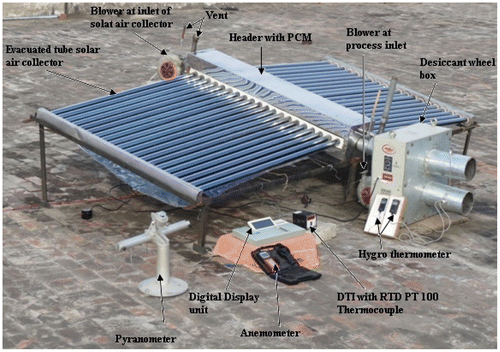
The schematic diagram and the photographic view of the PCM-based SPDWAC are shown in Figure . The system consists of an evacuated tube solar air collector subsystem (ETSAC integrated with PCM), DW subsystem. The heating of the air has been done using solar thermal evacuated tube subsystem and humidification of air is done with the help of DW. The SPDWAC has been utilised in the winter season to serve the purpose of space heating and humidification during nocturnal. For achieving this purpose the SPDWAC system has been integrated with PCM, which stores solar energy during day time and this stored energy is utilised to heat the air passing through the ETSAC during night-time when no solar intensity available in the sky. Then this hot air is passed through the DW and regeneration of DW takes place.
Figure 1a. Schematic diagram of the phase change material (PCM)-based solar powered desiccant wheel air conditioning (SPDWAC) system represents the sensor position.
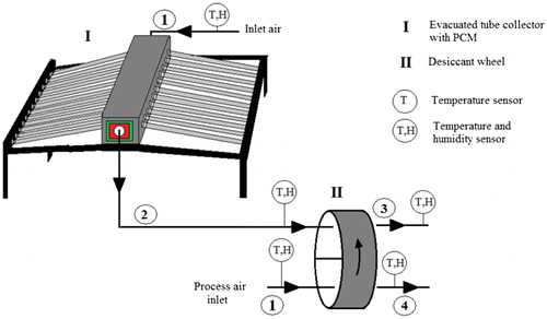
Figure 1b. Photograph of the phase change material (PCM)-based solar powered desiccant wheel air conditioning (SPDWAC) system.
2.1. ETSAC subsystem
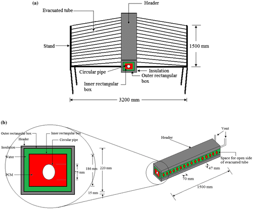
Figure shows the schematic representation of the ETSAC subsystem. This subsystem having 40 evacuated tubes with the collector area of 4.44 m2. Evacuated tube with two co-axial glass tubes is used in this subsystem having a length of 1500 mm. A header with two square cross section, namely outer square cross section (220 mm × 220 mm) and inner square cross section (186 mm × 186 mm) is used. While the former is used for the flow of water, later is used to store the 50 kg of PCM. The header is covered with an insulation of polyurethane, having the thermal conductivity of 0.023 W m−1 °C−1, to avoid the heat transfer from header to the environment. The header is 1500 mm in length, having a hollow circular pipe (75 mm diameter) at the centre through which the air passes. Solar thermal evacuated tube subsystem has the capacity of 100 L of water. Heat is stored in water by solar intensity, which is then transferred to PCM. The stored heat in acetamide (PCM) is transferred to the air passing through a hollow circular pipe. The melting temperature, latent heat of fusion of acetamide are 81 °C and 263 kJ kg−1 with the thermal conductivity of 0.5 W m−1 °C−1. A blower of 0.350 kW (AC mains) is used to blow the air in the ETSAC.
2.2. Desiccant wheel subsystem
The main part of the desiccant wheel subsystem is the DW as shown in Figure . The DW is an air to air heat and mass exchanger which rotates at low rotational speed. It is made up of a sinusoidal matrix with the regular silica gel coating. The DW has two equal zones, that is, regeneration zone and adsorption zone, which are separated by a partition and flexible seal. The DW is driven by a rotary motor of 6 W at different rotational speed to alter the position of the adsorption and regeneration zones. Table shows the dimension and properties of the desiccant wheel.
Figure 3. (a) Schematic diagrams of rotary desiccant wheel (b) Cross section of air flow channel with sinusoidal matrix
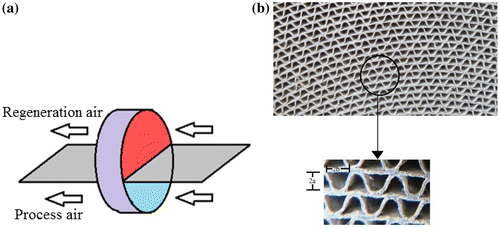
Table 1. Dimension and properties of DW [Yadav and Bajpai (Citation2012)].
2.3. Operation description of the system
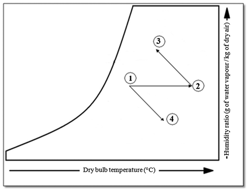
During the day of experiments, the ETSAC is exposed to Sun to gain solar heat and the filled water inside the tubes get heat and start to move towards the outer rectangular box of the header due to thermosyphon phenomenon. Thereafter, hot water transfers its heat to the PCM and PCM inside the inner rectangular box starts to store the heat during day hours. Afterwards, the stored heat of PCM is used to heat the air during off-sunshine hours when no solar intensity is available. Hence, during day hours the charging of PCM has been done and during off-sunshine hours the heating of air has been done using ETSAC. Now, this hot air is used to regenerate the DW. The DW has two equal zones as shown in Figure (a), namely adsorption zone and regeneration zone. In adsorption zone, the fresh air at point 1 moves inside the DW and leaves at point 4 and dehumidification of air occurs (stage 1–4). During this process, the adsorption heat released which increased the temperature of process air at point 4. The regeneration air is heated from point 1 to point 2 (shown in Figure (a)) by using ETSAC (stages 1–2), then regeneration of DW has been done from point 2 to point 3 (stages 2–3). Hence, during this process, the humidification of air occurs. In the winter season, this humid air is utilised to meet a comfort condition. So all this operation has been done during consecutive charging and discharging of the PCM. During during consecutive charging and discharging of the PCM, the charging of PCM is done for the period of existing solar intensity, i.e. from 10:00 to 18:00 h, later the heating and humidification of air is done for the period of discharging of the PCM from 18:00 to 24:00 h. When solar radiation falls on the ETSAC, the filled water in it is heated and this heat energy is transferred to the PCM. Then PCM starts storing the heat during day hours and it is utilised to heat the air during nocturnal.
A psychrometric chart representation of the experimental set-up is shown in Figure . The working principle of the system is summarised as follows:
| • | Process air: dehumidification (1–4) | ||||
| • | Regeneration air: solar heating (1–2) → regeneration (2–3). | ||||
Table 2. Specification of the measuring instruments.
3. Analysis of experimental data
The performance of the PCM-based SPDWAC has been evaluated in the winter season to achieve the heating and humidification during night-time on the basis of energy and exergy analysis. The full description of following parameters studied during energy and exergy analysis have been given as:
3.1. Energy analysis
The performance index such as efficiency of the ETSAC, dehumidification rate, regeneration rate, dehumidification effectiveness, regeneration effectiveness, thermal effectiveness of the DW, thermal coefficient of performance of the system () and exergy efficiency of the system (
) are used to evaluate the performance of the system:
The daytime efficiency of the ETSAC with PCM during heating of the PCM has been shown in Equation (Equation1(1) ).
(1)
The night-time efficiency of the ETSAC with PCM during heating of the air has been shown in Equation (Equation2(2) ) as:
(2)
The energy efficiency of the PCM storage system is given by Equation (Equation3(3) ) as follows:
(3)
Area of the ETSAC is given by Ma et al. (Citation2010)(4)
The dehumidification rate (DR) represents the rate of the moisture extracted from the air in adsorption zone and given as Kabeel (Citation2007)(5)
where Yp,in is the humidity ratio of the inlet process air; Yp,out is the humidity ratio of the outlet process air: and is the air flow rate of process air.
The regeneration rate (RR) represents the rate of the moisture added to the air in regeneration zone and given as Kabeel (Citation2007)(6)
where Yr,in is the humidity ratio of the inlet regeneration air; Yr,out is the humidity ratio of the outlet regeneration air: and is the air flow rate of regeneration air.
The dehumidification effectiveness (ɛD) indicates the ratio of moisture change during the dehumidification process to the moisture change when wheel is ideal as per Angrisani et al. (Citation2012)(7)
(8)
In case of ideal wheel, for adsorption, hence dehumidification effectiveness is written as follows:
(9)
The regeneration effectiveness () indicates the ratio of the moisture change during the regeneration process to the initial moisture as per Kabeel (Citation2007)
(10)
(11)
Thermal effectiveness () indicates the ratio of the thermal power related to process air heating through the wheel to the regeneration thermal power as per Angrisani et al. (Citation2012)
(12)
(13)
and
are the temperature of the inlet and the outlet process air, respectively, and
is the temperature of the inlet regeneration air.
Thermal coefficient of performance of the system () indicates the ratio of the heating capacity of the system from point 1 to point 3 to the regeneration heat input (as shown in Figure ) [Kanoglu, Bolatturk, and Altuntop (Citation2007)]
(14)
(15)
where h1, h2 and h3 are the enthalpy of the process air process air at the inlet of ETSAC, regeneration air at the inlet of DW and regeneration air at the outlet of DW, respectively.
3.2. Exergy analysis
The exergy efficiencies of the SPDWAC is evaluated as follows:
Exergy efficiency of the system () indicates the ratio of the exergy heating capacity of the system from point 1 to point 3 to the exergy regeneration heat input from point 1 to point 2 (as shown in Figure ) [Hurdogan et al. (Citation2011)]
(16)
(17)
where S1, S2 and S3 are the entropy of the process air at the inlet of ETSAC, regeneration air at the inlet of desiccant wheel and regeneration air at the outlet of desiccant wheel, respectively.
where specific entropy change is given by Park et al. (Citation2014) as follows:(18)
(19)
The exergy efficiency of the PCM storage system is given by Equation (Equation20(20) ) as follows:
(20)
4. Results and discussion
The performance of the experimental set-up for heating and humidification has been conducted in the months of February and March 2015. During the experiments, the rotational speed of the DW is fixed (16 rph) and air flow rate varies from 63.62 kg h−1 to 127.23 kg h−1.
4.1. Case 1: performance analysis of the SPDWAC at low air flow rate of 63.62 kg h−1 (27/02/2015)
Figure shows the variation of ambient temperature, PCM temperature, water temperature and solar radiation with time. Initially, the temperature of PCM increases slightly, because water is gaining heat from the solar intensity and transfer a small amount of heat to the PCM. Thereafter, the temperature of PCM increases sharply and achieved its maximum value (98.2 °C), because water starts to transfer maximum heat to the PCM. The duration from 9:00 to 18:00 h shows the charging of PCM and duration from 18:00 to 24:00 h shows the discharging of PCM. From the variation of graph, it has been seen that PCM has an adequate amount of temperature for the night operation. As compare to the system presented by Yadav and Bajpai (Citation2012), the present system worked well during night-time and achieved the temperature of water (63.4 °C) at 24:00 h. While as per Yadav and Bajpai (Citation2012) at 24:00 h the temperature of water becomes equal to the ambient temperature.
Figure 5. Variation of temperatures and solar intensity with time at a flow rate of 63.62 kg h−1 (27/02/2015)
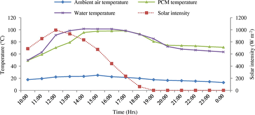
Figure shows the variation of regeneration rate, dehumidification rate and regeneration temperature with time. On 27 February, after storing heat in PCM up to 18:00 h, the blower is switched on and air starts to blow through a hollow circular pipe of the collector. The performance of the SPDWAC has been evaluated for a flow rate of 63.62 kg h−1. It remarked that initially, the regeneration rate is more as compared to the dehumidification rate and at 21:00 h it started decreasing and became lower than the dehumidification rate. So, it indicates that regeneration rate is more dependent upon regeneration temperature. The decrement rate of regeneration rate is quicker than dehumidification rate when regeneration temperature is approaching below 43 °C. The regeneration rate and dehumidification rate changes from 0.168 to 0.048 kg h−1 and 0.145 to 0.075 kg h−1, respectively. It is noted that the average regeneration rate and dehumidification rate was 0.111 and 0.107 kg h−1, respectively, for the duration of 18:00 to 24:00 h. From Figure , it has been observed that with the utilisation of PCM as a heat storage system the regeneration rate of desiccant wheel is obtained during night-time.
Figure 6. Variation of regeneration rate, dehumidification rate and regeneration temperature with time for a flow rate of 63.62 kg h−1 (27/02/2015)
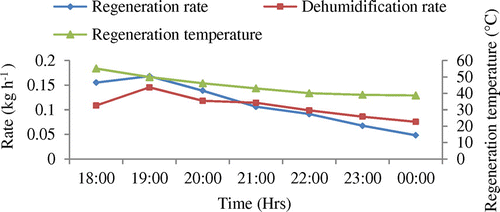
Figure depicts the profile of regeneration effectiveness, dehumidification effectiveness and regeneration temperature with time. The regeneration effectiveness and dehumidification effectiveness lies in the range of 0.363–0.095 and 0.314–0.149, respectively. The average regeneration effectiveness and dehumidification effectiveness are 0.234 and 0.224, respectively. Initially, the regeneration effectiveness is more as compared with the dehumidification effectiveness and at 21:00 h it started decreasing and became lower than the dehumidification effectiveness. As mentioned before that regeneration rate is more dependent upon regeneration temperature, which directly influences the regeneration effectiveness. Hence, regeneration effectiveness is decreased quicker than dehumidification effectiveness when regeneration temperature is approaching below 43 °C. Again Figure confirms the utilisation of PCM as a storage of heat which makes the system feasible during hours of darkness.
Figure 7. Variation of regeneration effectiveness, dehumidification effectiveness and regeneration temperature with time for a flow rate of 63.62 kg h−1 (27/02/2015)
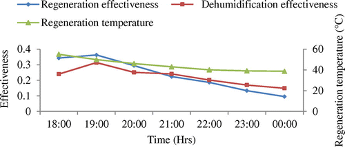
Figure illustrates the variation of thermal effectiveness and regeneration temperature with time. It is seen that the thermal effectiveness increases with the decrease in regeneration temperature. The maximum and minimum thermal effectivenesses are 0.357 and 0.267, respectively, and the average thermal effectiveness is 0.328 at an average regeneration temperature of 44.6 °C. From Figure it has been observed that with the utilisation of PCM as a heat storage system the adequate regeneration temperature to regenerate the desiccant wheel is obtained during off-sunshine hours and again the thermal effectiveness of the system is obtained.
Figure 8. Variation of thermal effectiveness and regeneration temperature with time for a flow rate of 63.62 kg h−1(27/02/2015)
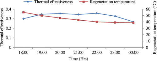
Figure shows the profile of COPs of the system and heating capacity with time. The maximum and minimum COPs of the system are 0.153 and 0.0703, respectively, and the average COPs is 0.121. The profile of COPs of the system decreases with time because the temperature of outlet process air starts to decrease. The maximum heating capacity of 475.7 W is achieved and the average heating capacity is 334.3 W. Also, the heating capacity of 175.3 W is obtained at the end of the experiment (24:00 h). Hence, it shows that the PCM as a storage medium is able to run the SPDWAC system from 18:00 to 24:00 h.
Figure 9. Variation of thermal coefficient of performance of the system and heating capacity with time for a flow rate of 63.62 kg h−1(27/02/2015)
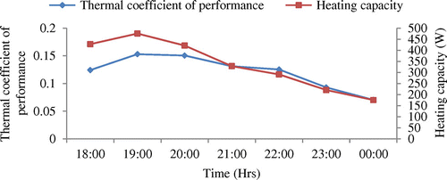
Figure shows the profile of exergy efficiency of system and exergy heating capacity with time. The maximum and minimum exergy efficiencies of the system are 0.1133 and 0.0256, respectively, and the average exergy efficiency of the system is 0.0787. The profile of exergy efficiency of the system decreases with time. The maximum exergy heating capacity of 241.2 W is achieved and the average exergy heating capacity is 141.2 W. Also, the exergy heating capacity of 42.06 W is obtained at the end of the experiment (24:00 h). So, all these results at low air flow rate established the feasibility of PCM to run the SPDWAC system during off-sunshine hours.
4.2. Case 2: performance analysis of the SPSDAC at low air flow rate of 127.23 kg h−1 (04/03/2015)
Figure shows the variation of ambient temperature, PCM temperature, water temperature and solar intensity with time. Initially, the temperature of PCM increases slightly, because water is gaining heat from the solar intensity and transfer a small amount of heat to the PCM. Thereafter, the temperature of PCM increases sharply and achieved its maximum value (89.5 °C), because water starts to transfer maximum heat to the PCM. The duration from 9:00 to 18:00 h shows the charging of PCM and duration from 18:00 to 24:00 h shows the discharging of PCM. From the variation of graph, it has been seen that PCM has an adequate amount of temperature for the night operation.
Figure 11. Variation of temperatures and solar intensity with time for a flow rate of 127.23 kg h−1 (04/03/2015)
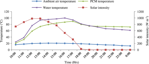
Figure shows the variation of regeneration rate, dehumidification rate and regeneration temperature with time. On 4 March, the performance of the system has been evaluated for a flow rate of 127.23 kg h−1. It remarked that initially the dehumidification rate is more as compared to the regeneration rate and starts decreasing below the value of regeneration rate after 22:00 h. So, it indicates that decrement rate of regeneration rate is more than the dehumidification rate for high air flow rate. The regeneration rate and dehumidification rate changes from 0.184 to 0.059 kg h−1 and 0.209 to 0.042 kg h−1, respectively. It has been observed that the average regeneration rate and dehumidification rate are 0.113 and 0.135 kg h−1, respectively. The dehumidification rate for high air flow rate is 1.26 times that at low air flow rate and the regeneration rate for high air flow rate is 1.018 times that at low air flow rate. From Figure it has been observed that with the utilisation of PCM as a heat storage system the regeneration rate of desiccant wheel is obtained during night-time.
Figure 12. Variation of regeneration rate, dehumidification rate and regeneration temperature with time for a flow rate of 127.23 kg h−1 (04/03/2015)
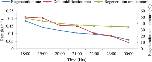
Figure depicts the profile of regeneration effectiveness, dehumidification effectiveness and regeneration temperature with time. The regeneration effectiveness and dehumidification effectiveness changes from 0.163 to 0.0569 and 0.185 to 0.039, respectively. It has been concluded that the average regeneration effectiveness and dehumidification effectiveness are 0.102 and 0.122, respectively. It has been observed that the dehumidification effectiveness for low air flow rate is 1.84 times that at high air flow rate and the regeneration effectiveness for low air flow rate is 2.29 times that at high air flow rate. Again Figure confirms the utilisation of PCM as a storage of heat which makes the system feasible during hours of darkness.
Figure 13. Variation of regeneration effectiveness, dehumidification effectiveness and regeneration temperature with time for a flow rate of 127.23 kg h−1 (04/03/2015)
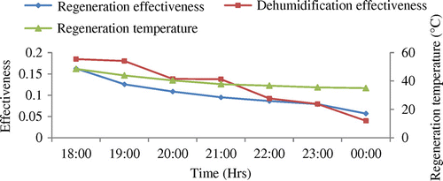
Figure shows the variation of thermal effectiveness and regeneration temperature with time for an air flow rate of 127.23 kg h−1 in both zones. Initially, the thermal effectiveness starts from 0.556 and reaches the maximum value of 0.789 at 20:00 h and then starts to decrease 0.749 at the end of the experiment. The average thermal effectiveness is 0.714 at an average regeneration temperature of 39.7 °C. It is noticed that the thermal effectiveness for high air flow rate is 2.18 times that at low air flow. From Figure , it has been observed that with the utilisation of PCM as a heat storage system the adequate regeneration temperature to regenerate the desiccant wheel is obtained during off-sunshine hours and again the thermal effectiveness of the system is obtained.
Figure 14. Variation of thermal effectiveness and regeneration temperature with time for a flow rate of 127.23 kg h−1 (04/03/2015)
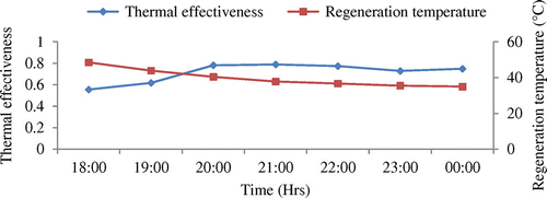
Figure shows the variation of COPs of the system and heating capacity with time at an air flow rate of 127.23 kg h−1. The maximum and minimum COPs of the system are 0.211 and 0.129, respectively. The average COPs of the system is 0.172. The COPs for high air flow rate is 1.42 times that at low air flow rate. The maximum heating capacity of 608.7 W is achieved and the average heating capacity is 580.1 W. The average heating capacity at high air flow rate is 1.74 times that at low air flow rate.
Figure 15. Variation of thermal coefficient of performance of the system and heating capacity with time for a flow rate of 127.23 kg h−1 (04/03/2015)
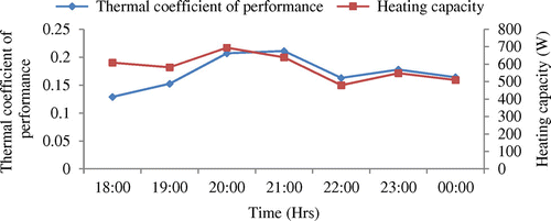
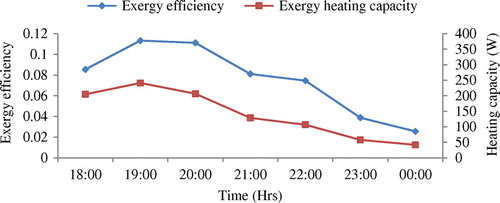
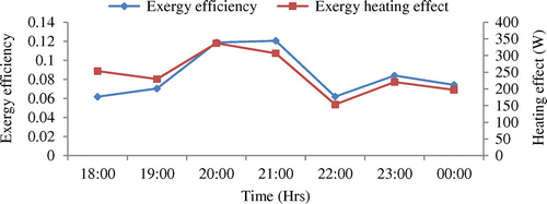
Figure shows the profile of exergy efficiency of the system and exergy heating capacity with time. The maximum and minimum exergy efficiencies of the system are 0.1206 and 0.0619, respectively, and the average exergy efficiency is 0.0846. The maximum exergy heating capacity of 337.2 W is achieved and the average exergy heating capacity is 242.6 W. The average exergy heating capacity at high air flow rate is 1.72 times that at low air flow rate. So all these results at high air flow rate established the feasibility of PCM to run the SPDWAC system during off-sunshine hours.
Figure 16. Variation of exergy efficiency of the system and exergy heating effect with time for a flow rate of 127.23 kg h−1 (04/03/2015)
The performance analysis of PCM-based SPDWAC is presented in Table . It has been observed that the maximum average collector efficiency is 15.60% at a high air flow rate of 127.23 kg h−1. Also, the maximum average energy efficiency and exergy efficiency of the PCM storage system has been obtained at high air flow rate. The advantages of PCM-based SPDWAC over systems using no storage material is that it is worked well during off-sunshine hours. Another advantage of it is that the hot air is produced during off-sunshine hours up to 24:00 h. So using PCM as storage material, the working hours of the experimental set-up is increased. Hence, it has been seen that heating and humidification during off-sunshine hours is possible with the use of PCM-based SPDWAC system.
Table 3. Performance analysis of PCM-based SPDWAC.
5. Conclusions
In the present study, the performance of PCM-based SPDWAC system has been analysed experimentally. A novel design of header with the PCM storage unit was used to store solar energy during sunshine hours to serve the purpose of heating and humidification during off-sunshine hours. The important conclusions are taken from the experimental results as listed below:
| (1) | The experimental set-up has the considerable proficiency to meet the heating and humidification demand during the winter season in the night-time. The system runs effectively for 7 h during night operation using 50 kg of acetamide (PCM) as a heat storage medium. | ||||
| (2) | The average dehumidification rate for high air flow rate (127.23 kg h−1) is 1.26 times that of at low air flow rate (63.62 kg h−1) and the average regeneration rate for high air flow rate is 1.02 times as compared to the low air flow rate. | ||||
| (3) | The average dehumidification effectiveness for low air flow rate (63.62 kg h−1) is 1.84 times as compared to the high air flow rate (127.23 kg h−1) and the regeneration effectiveness for low air flow rate (63.62 kg h−1) is 2.29 times as compared to the high air flow rate (127.23 kg h−1). | ||||
| (4) | The average ɛTh of the system at the air flow rate of 127.23 kg h−1 is 2.18 times that of at the air flow rate of 63.62 kg h−1 with the constant rotational speed (16rph) of the wheel. | ||||
| (5) | The average COPs of the system at an air flow rate of 127.23 kg h−1 is 1.42 times that of at an air flow rate of 63.62 kg h−1. Also, the average Esystem of the system at high air flow rate is 1.07 times that of at low air flow rate. | ||||
| (6) | The average heating capacity and average exergy heating capacity of the system increases with the increase in air flow rate. It has been observed that the average heating capacity at high air flow rate is 1.74 times that of at low air flow rate and the average exergy heating capacity at high air flow rate is 1.72 times that of at low air flow rate. | ||||
| (7) | It is observed that with the increase in air flow rate the efficiency of the ETSAC increases. The maximum average efficiency of the ETSAC at high air flow rate is 15.60%. | ||||
| (8) | The system is highly efficient when it has been functioned at high air flow rate. The maximum average energy efficiency (17.80%) and exergy efficiency (17.08%) of the PCM storage system have been obtained at high air flow rate. | ||||
| Nomenclature | ||
| Acollector | = | area of collector, m2 |
| cpa | = | specific heat of air, (kJ kg−1 °C−1) |
| cPCM | = | specific heat of PCM, (kJ kg−1 °C−1) |
| cwater | = | specific heat of water, (kJ kg−1 °C−1) |
| COPs | = | thermal coefficient of performance of system |
| ɛD | = | dehumidification effectiveness in process zone |
| ɛRE | = | regeneration effectiveness in regeneration zone |
| ɛTh | = | thermal effectiveness |
| Esystem | = | exergy efficiency of the system |
| EPCM | = | exergy efficiency of the PCM storage system |
| ηcollector | = | efficiency of ETSAC |
| ηPCM | = | energy efficiency of the PCM storage system |
| D | = | diameter of evacuated tube, m |
| ETC | = | evacuated tube collector |
| G | = | solar intensity, (W m−2) |
| h | = | enthalpy of air (kJ kg−1) |
| in | = | inlet |
| L | = | latent heat of fusion, (kJ kg−1) |
| l,PCM | = | PCM during liquid phase |
| s,PCM | = | PCM during solid phase |
| mPCM | = | mass of PCM, kg |
| mwater | = | mass of water, kg |
| = | air flow rate of process air (kg h−1) | |
| = | air flow rate of regeneration air (kg h−1) | |
| N | = | rotation (rph) |
| out | = | outlet |
| DR | = | adsorption rate (kg h−1) |
| RR | = | regeneration rate (kg h−1) |
| Y | = | humidity ratio of the air (kgwater vapour kgdry air−1) |
| θp | = | angular zone of process air (degree) |
| θr | = | angular zone of regeneration air (degree) |
| Tamb | = | ambient temperature (°C) |
| Tp | = | temperature of process air (°C) |
| Tr | = | temperature of regeneration air (°C) |
Notes on contributors
Neeraj Mehla, PhD, is an assistant professor of Mechanical Engineering at the National Institute of technology, Kurukshetra, Haryana, India. His current interests are in solar desiccant air-conditioning system, phase change materials, and solar updraft tower. Previous publications have appeared in Drying Technology, Ambient energy and Indoor and built environment, and others. The areas of interest of both authors are sustainability, solar air-conditioning, climate change and environment engineering.
Avadhesh Yadav, PhD, is an assistant professor of Mechanical Engineering at the National Institute of technology, Kurukshetra, Haryana, India. His main research interests are in desiccant air-conditioning system, phase change materials, solar concentrator, and solar cooking, Low and high temperature applications of solar energy. He has published more than 30 papers in international journals in the field of Renewable energy resources and others. The areas of interest of both authors are sustainability, solar air- conditioning, climate change and environment engineering.
Disclosure statement
No potential conflict of interest was reported by the authors.
References
- Al-Kayiem, H. H., and S. C. Lin. 2014. “Performance Evaluation of a Solar Water Heater Integrated with a PCM Nanocomposite TES at Various Inclinations.” Solar Energy 109: 82–92.10.1016/j.solener.2014.08.021
- Angrisani, G., F. Minichiello, C. Roselli, and M. Sasso. 2012. “Experimental Analysis on the Dehumidification and Thermal Performance of a Desiccant Wheel.” Applied Energy 92: 563–572.10.1016/j.apenergy.2011.11.071
- Charoensupaya, D., and W. M. Worek. 1988. “Parametric Study of an Open-cycle Adiabatic, Solid, Desiccant Cooling System.” Energy 13 (9): 321–328.
- Chen, C. H., C. Y. Hsu, C. C. Chen, and Y. C. Chiang. 2016. “Silica Gel/polymer Composite Desiccant Wheel Combined with Heat Pump for Air-CONDITIONING Systems.” Energy 94: 87–99.10.1016/j.energy.2015.10.139
- Enteria, N., H. Yoshino, R. Takaki, H. Yonekura, A. Satake, and A. Mochida. 2013. “First and Second Law Analyses of the Developed Solar-desiccant Air-conditioning System (SDACS) Operation during the Summer Day.” Energy and Buildings 60: 239–251.10.1016/j.enbuild.2013.01.009
- Ge, T. S., Y. J. Dai, and Y. Li. 2013. “Feasible Study of a Self-cooled Solid Desiccant Cooling System Based on Desiccant Coated Heat Exchanger.” Applied Thermal Engineering 58: 281–290.10.1016/j.applthermaleng.2013.04.059
- Guidara, Z., M. Elleuch, and H. B. Bacha. 2013. “New Solid Desiccant Solar Air Conditioning Unit in Tunisia: Design and Simulation Study.” Applied Thermal Engineering 58: 656–663.10.1016/j.applthermaleng.2013.05.005
- Hurdogan, E., O. Buyukalaca, T. Yılmaz, A. Hepbasli, and T. Yilmaz. 2011. “Exergetic Modeling and Experimental Performance Assessment of a Novel Desiccant Cooling System.” Energy and Buildings 43: 1489–1498.10.1016/j.enbuild.2011.02.016
- Jani, D. B., M. Mishra, and P. K. Sahoo. 2016. “Solid Desiccant Air Conditioning - a State of the Art Review.” Renewable and Sustainable Energy Reviews 60: 1451–1469.10.1016/j.rser.2016.03.031
- Kabeel, A. E. 2007. “Solar Powered Air Conditioning System Using Rotary Honeycomb Desiccant Wheel.” Renewable Energy 32: 1842–1857.10.1016/j.renene.2006.08.009
- Kanoglu, M., A. Bolatturk, and N. Altuntop. 2007. “Effect of Ambient Conditions on the First and Second Law Performance of an Open Desiccant Cooling Process.” Renewable Energy 32: 931–946.10.1016/j.renene.2006.04.001
- La, D., Y. Dai, H. Li, Y. Li, J. K. Kiplagat, and R. Wang. 2011. “Experimental Invesingation and Theoretical Analysis of Solar Heating and Humidification System with Desiccant Rotor.” Energy and Buildings 43: 1113–1122.10.1016/j.enbuild.2010.08.006
- Li, H., Y. J. Dai, Y. Li, D. La, and R. Z. Wang. 2011. “Experimental Investigation on a One-rotar Two-stage Desiccant Cooling/heating System Driven by Solar Air Collectors.” Applied Thermal Engineering 31: 3677–3683.10.1016/j.applthermaleng.2011.01.018
- Li, H., Y. J. Dai, D. La, and R. Z. Wang. 2012. “Case Study of a Two-stage Rotary Desiccant Cooling/heating System Driven by Evacuated Glass Tube Solar Air Collectors.” Energy and Buildings 47: 107–112.10.1016/j.enbuild.2011.11.035
- Longo, G. A., and A. Gasparella. 2015. “Three Years Experimental Comparative Analysis of a Desiccant Based Air Conditioning System for a Flower Greenhouse: Assessment of Different Desiccants.” Applied Thermal Engineering 78: 584–590.10.1016/j.applthermaleng.2014.12.005
- Ma, L., Z. Lu, J. Zhang, and R. Liang. 2010. “Thermal Performance Analysis of the Glass Evacuated Tube Solar Collector with U-tube.” Building and Environment 45: 1959–1967.10.1016/j.buildenv.2010.01.015
- Mahfuz, M. H., M. R. Anisur, M. A. Kibria, R. Saidur, and I. H. S. C. Metselaar. 2014. “Performance Investigation of Thermal Energy Storage System with Phase Change Material (PCM) for Solar Water Heating Application.” International Communications in Heat and Mass Transfer 57: 132–139.10.1016/j.icheatmasstransfer.2014.07.022
- Park, S. R., A. K. Pandey, V. V. Tyagi, and S. K. Tyagi. 2014. “Energy and Exergy Analysis of Typical Renewable Energy Systems.” Renewable and Sustainable Energy Reviews 30: 105–123.10.1016/j.rser.2013.09.011
- Sarbu, I. 2014. “A Review on Substitution Strategy of Non-Ecological Refrigerants from Vapour Compression-based Refrigeration, Air-conditioning and Heat Pump Systems.” International Journal of Refrigeration 46: 123–141.10.1016/j.ijrefrig.2014.04.023
- Sheng, Y., Y. Zhang, Y. Sun, L. Nie, J. Fang, and Ma, L. 2014. “Experimental Analysis and Regression Prediction of Desiccant Wheel Behavior in High Temperature Heat Pump and Desiccant Wheel Air-conditioning System.” Energy and Buildings 80: 358–365.10.1016/j.enbuild.2014.05.040
- Summers, E. K., M. A. Antar, and J. H. Lienhard. 2012. “Design and Optimization of an Air Heating Solar Collector with Integrated Phase Change Material Energy Storage for Use in Humidification–Dehumidification Desalination.” Solar Energy 86: 3417–3429.10.1016/j.solener.2012.07.017
- Uckan, I., T. Yilmaz, E. Hurdogan, and O. Buyukalaca. 2013. “Experimental Investigation of a Novel Configuration of Desiccant Based Evaporative Air Conditioning System.” Energy Conversion and Management 65: 606–615.10.1016/j.enconman.2012.09.014
- Yadav, A., and V. K. Bajpai. 2012. “The Performance of Solar Powered Desiccant Dehumidifier in India: An Experimental Investigation.” International Journal of Sustainable Engineering 6 (3): 239–257.
- Yang, L., X. Zhang, and G. Xu. 2014. “Thermal Performance Evaluation of a Solar Storage Packed Bed Using Spherical Capsules Filled with PCM Having Different Melting Points.” Energy and Buildings 68: 639–646.10.1016/j.enbuild.2013.09.045
- Zeng, D. Q., H. Li, Y. J. Dai, and A. X. Xie. 2014. “Numerical Analysis and Optimization of a Solar Hybrid One-rotor Two-stage Desiccant Cooling and Heating System.” Applied Thermal Engineering 73: 474–483.10.1016/j.applthermaleng.2014.07.076

