Abstract
The design of a new power management tool able to manage the power flow from different renewable energy sources is proposed in this paper. PV and wind are the primary power sources for the system, and a fuel cell with electrolyser and batteries are used as reserve. The designed controller purpose is to manage power flows among the different energy systems and to assure a continuous supply of load. Modelling and simulation of the various energy sources of distributed generation (DG) systems including wind turbine (WT), fuel cell-electrolyser (FC), photovoltaic (PV) and battery are developed. The coordination controller is designed based on the criteria of providing the load demand and the excess power is used either to produce hydrogen through electrolyser for the FC or to store it in battery. Simulation is carried out in MATLAB/Simulink environment and the results show satisfactory performance of the coordination scheme to satisfy the load requirements.
1. Introduction
The use of fossil-based energy sources is costly and not environment friendly. On the other hand, renewable energy sources (RES) are secure, reliable and environment friendly. The current trend in the power industry shows a high demand for RES. A big share of this high demand goes to photovoltaic (PV) and wind turbine (WT) energy systems. Due to the intermittent nature of PV and WT sources and to ensure high reliability, PV and WT are used along with other energy source, like Fuel cell (FC) and/or battery bank. Combination of these sources has great potential to provide a reliable and environmentally friendly power source to customers.
Seasonal and daily variations of the weather conditions require design of a robust and reliable energy system in order to compensate the impacts of the RES fluctuations. One way to overcome this problem is to use energy storage devices. The excess energy available from RES could be stored and used when needed. Battery bank is normally used as a short-term energy source due to its fast charging/discharging and hence suitable for smoothing the fluctuations of both load demand and RES. For long-term energy backup, the battery bank is not appropriate due to the low energy density. The FC equipped with electrolyser and hydrogen tank can be used for long-term energy storage. This is mainly because the frequent start-up and shutdown actions degrade the electrolyser and the FC performance.
Oman has large areas that have abundant of solar radiations that can be utilised to generate substantial amount of energy. Wind speed has an average value of more than 5 m/s in several locations in Oman and can be used to provide part of the energy based on the load requirement (Al-Badi, Al-Toobi et al. Citation2011). The technologies for both wind and PV are mature and recently the cost of PV has reduced dramatically. Fuel Cell (FC) technology has many advantages such as high efficiency, low emission and flexible modular structure. Owing to its high efficiency and flexible modular structure, a hybrid renewable energy system (PV and WT) with FC technology has been proposed by various researchers (Al-Badi Citation2012; Al-Badi, Al-Badi et al. Citation2011; Ipsakisa et al. Citation2009; Wang and Nehrir Citation2008; Zhou, Ferreira, and de Haan Citation2008, Agbossou et al. Citation2004). This system can feed stand-alone loads or can be strategically placed at any site in a power network for grid reinforcement. Thus, deferring the need for system upgrades and improving system efficiency, integrity and reliability.The distributed generation (DG) system considered in this paper consists of two main RES, namely the PV and WT and two energy storage elements, namely a FC and a battery bank.
For better coordination between different energy sources in a DG, a power management scheme has to be incorporated. The main decision factors for any power management strategy are the level of the power provided by each renewable energy source (PV &WT), the load demand and the state of charge of the battery bank. The battery bank and/or the fuel cell should be able to provide the required power whenever necessary. Based on the load requirement and the availability of generated power from each source, a power management strategy is developed to guarantee continuous supply of energy to the load. Different energy management strategies of RES have been used in different applications. A control strategy for active power flow in a hybrid fuel cell/battery distributed generation system is proposed in (Hajizadeh and Golka Citation2007). Based on multi-agent systems, a power management solution is presented in (Lagorse, Paire, and Miraoui Citation2010). The authors of (Colson and Nehrir Citation2009) address a qualitative framework for the power management and control architectures of microgrids. The authors of (Dursun and Kilic Citation2012) presented different power management strategies and investigated their effects on the efficiency of battery banks and on the life span of fuel cell membrane. Real and reactive power control and droop control are developed for different combination of DG and storage units in a microgrid (Bai, Abedi, and Lee Citation2016). Energy management strategies have recently applied in transportation engineering (Bassam et al. Citation2016; Li et al. Citation2015). A classical proportional-integral (PI) controller-based energy management strategy is presented to realise the benefits of hybrid fuel cell power systems used in transportation applications (Bassam et al. Citation2016). A hybrid power-train configuration based on FC of a proton exchange membrane (PEMFC) type, a battery and a supercapacitor (SC) is designed without grid connection for tramway is considered in (Li et al. Citation2015). The proposed energy management strategy (Li et al. Citation2015) is based on a combination of fuzzy logic control Haar wavelet transform.
In this paper, a simple power management strategy is proposed to ensure that the load is supplied in an interrupt-free manner. It is based on monitoring the load demand and then activate the appropriate energy source to handle it. Any surplus of generated energy is directed to be stored in the battery bank or used to produce hydrogen required for the operation of FC. To prevent frequent starting and stopping of the FC-electrolyser system, any short-term load increase beyond the capabilities of both PV and WT will be supplied by the battery bank. However, the long-term load demand when the PV is not active will be taken care by the FC. Thus the proposed power management scheme has the advantages of reducing the switching cycles of the FC and eliminating the need for dump load. The overall DG system with the proposed energy management scheme installed is simulated in the MATLAB/Simulink environment. Simulation results verified the energy balance between the load demand and the output from different energy sources.
The remaining parts of the paper are organised as follows. The system sizing is discussed in Section 2. The description of the DG system used in the paper is presented in Section 3. Modelling of PV, WT, FC and batteries are given in Section 4 along with their simulated outputs. Section 5, gives the design of power management strategy and simulation of the overall system. The paper is concluded in Section 6.
2. System sizing
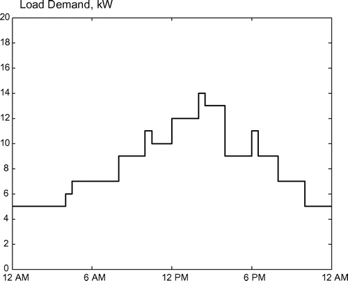
The proper sizing of the different energy units in a DG system is a major challenge. The factors that affect unit sizing are the weather conditions at the place of installation and the overall cost of each unit. The system sizing used in this paper is assumed for an eco-house with a daily load duration curve shown in Figure . The system is properly sized to assure reliable electrical supply to the house. A 15 kW wind turbine is assumed to be available for the hybrid system. The size for the other system components can be determined as follow. WT and PV units are the main energy sources for the eco-house, to balance the generation and demand over a period of time. The power balance equation is given by
where and
are the actual average output power of the PV and WT units, respectively. These powers can be determined in terms of the rated power and the capacity factor as per the following equations
where CF is the capacity factor defined as the ratio between the actual average power over a period of time and the rated power. It was reported in (Al-Badi et al. Citation2011) that based on metrological data in Oman, the capacity factors of PV unit is 0.18 and for the WT is 0.13 (Albadi and El-Saadany Citation2010). The values and
represent the power rating of PV and WT, respectively, and
is the load demand over a period of time. The load demand assumed in this paper is 10 kW.
Thus, the size of PV source can be calculated as:
The FC needs to provide the peak load demand when there is no solar and wind power available. Thus, the size of FC is considered as 15 kW. The electrolyser should be able to handle the excess power from wind and solar power sources that exceeds the requirement of the minimum load demand. The maximum excess power is calculated as = 55 kW.
However, it is less likely that both solar and wind power reach their maximum values when the load demand is minimum. Thus the size of electrolyser is chosen to be 20 kW. Sizing of each system components are summarised in Table and details specifications for the main system components are presented in Table .
Table 1. Sizing of system components.
Table 2. Specifications of system components.
3. System description
An autonomous stand-alone renewable energy system consisting of PV and WT needs storage devices to provide energy during fluctuating periods of these sources. The FC with hydrogen production through electrolyser is used to support the load when the power output is not sufficient for long period. Moreover, in order to account for short term energy variation, battery bank is normally used due to its fast response. The hybrid system considered in this paper consists of a PV subsystem with maximum power point tracking controller, WT, FC and battery bank. The load is fed through power management system.
4. Modelling of DG system components
In this section, modelling and sizing of the different system units are presented. In this section, we considered that at a given time both PV and Wind turbine are only producing 5 kW each. The output power of the FC and the battery bank, as storage subsystems, are assumed to be 5 and 1 kW, respectively.
4.1. PV model
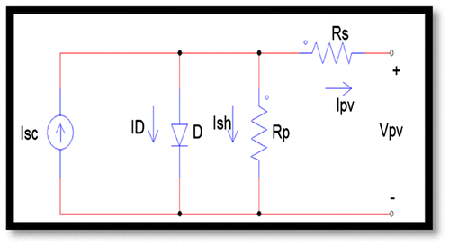
The model of a PV cell is shown in Figure (Soto, Klein, and Beckman Citation2006) and the general V–I equation can be expressed by (1)(1) where
and I0 are the short-circuit current, the diode current, the shunt current, the PV output current and the reverse saturation current respectively. The variable x is defined by
(2)
where q is the electron charge, k is the Boltzmann constant (1.38), A is the curve fitting factor, T is the cell temperature (K), Ns is the number of series-connected cells,
is the PV output voltage and RS and Rp are the series and shunt resistances of the model. The I–V and the P–V characteristics of a solar module depend on the temperature T, the short-circuit current
and the open-circuit voltage
. The following equations determine ISC and VOC
(3)
(4)
where S is the in-plane solar irradiance, is the reference irradiance,
is the reference temperature, α and β are the temperature coefficients and δ is the irradiance correction factor.
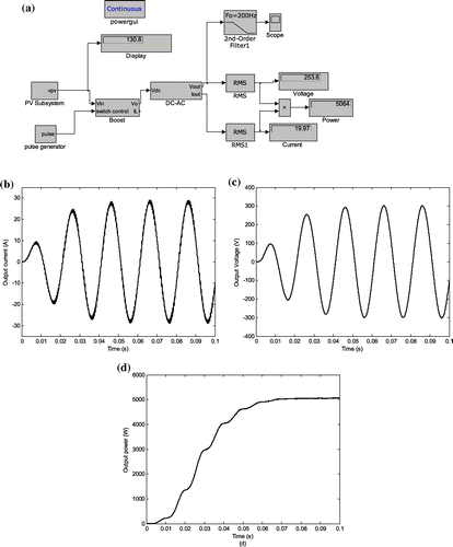
A Simulink model of the PV subsystem based on the above equations is shown in Figure (a). The PV subsystem consists of six modules connected in series with module open-circuit voltage of and short-circuit current of
. The current and voltage waveforms and the total output power are shown in Figure (b), (c) and (d), respectively.
4.2. Wind turbine model
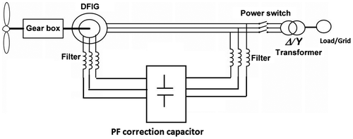
Nowadays, the wind energy system is used in stand-alone and grid-connected operations. The wind energy system considered in this paper consists of a wind turbine, a doubly fed induction generator (DFIG), and a power factor correction as depicted in Figure . The ideal wind turbine output power is given by (5) (Muyeen, Tamura, and Murata Citation2009):(5) where, A is the Rotor swept area in m2, ρ is the air density in kg/m3 and vW is the wind speed. The output electrical power extracted from the wind power by a practical WT is given by (6)
(6)
where is termed as the performance coefficient which is a function of the tip speed ratio
and the blade pitch angle β.
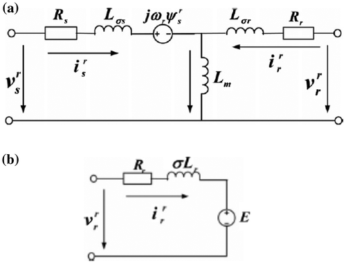
The DFIG model has been developed using the well-known Park’s transformation. Based on the equivalent circuit shown in Figure (a), the mathematical model is given in (7–10) (Hu et al. Citation2011) as:(7)
(8)
(9)
(10) where subscripts s and r denote the stator and rotor, respectively, superscript r denotes that the equations are expressed in the rotor reference,
,
represent voltages,
,
represent currents, Rs and Rr represent resistances, Ls and Lr represent self-inductances and Lm represents mutual inductance. Using (9) and (10), the rotor flux can be expressed as
(11)
Figure 5. (a) Equivalent circuit of a DFIG and (b) Equivalent circuit of a DFIG viewed from the rotor side.
where . Substituting (11) into (8), the rotor voltage is written as
(12)
From (12), it is clear that the rotor voltage consists of two terms, the first term is the electromotive force, E, induced by the stator flux and the second term represents the voltage drop across the rotor resistance Rr and the rotor leakage flux σLr. Therefore, from (12), the equivalent circuit of a DFIG viewed from the rotor side is obtained as shown in Figure (b) (Lopez et al. Citation2007).
Figure 6. Simulink model of Wind energy subsystem (a), Simulation results (b) Phase current (c) Phase voltage.
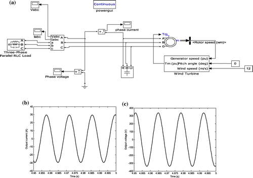
A Simulink model of a WT coupled with a DFIG is developed as given in Figure (a). The phase current and phase voltage are shown in Figure (b) and (c). The RMS phase current and voltage are 20.9 A and 240 V, respectively. The total power output of the wind energy subsystem per phase is calculated as 5.0 kW.
4.3. Fuel cell and electrolyser models
Fuel cells (FC) are static energy conversion devices that convert chemical energy into DC electrical energy (Larminie and Dicks Citation2003). The hydrogen required for FC operation is produced via electrolysis process of water. A combination of FC and Electroliser can be used as a back-up energy source to supply the required load for long period when the PV and WT sources are idle. There are mainly three types of fuel cells, namely the polymer electrolyte membrane fuel cell (PEMFC), the solid oxide fuel cells (SOFC) and molten carbonate fuel cells (MCFC). The PEMFC is widely used in stand-alone hybrid energy systems applications due to its high efficiency (40–45%), high power density and low operating temperature (between 60 °C and 80 °C) (Wang Citation2006). In this paper, we consider the PEMFC type.
4.3.1. Fuel cell model (Dash and Bajpai Citation2015; Tremblay and Dessaint Citation2009)
The output voltage of the FC, Vfc, is given by(13)
where E is the internal developed voltage, Vact is the activation voltage drop, Vc is the developed voltage across the capacitor and VΩ is the resistive voltage drop. The FC consumption rate of hydrogen, , depends on the FC current, Ifc, and is given as
(14)
where F is the Faraday’s constant. The net heat generated inside the FC due chemical reaction is expressed as(15)
where qnet is the net heat energy, qch is the chemical heat energy, qel is the electrical energy, qsl is the sensible and latent heat, qloss is the heat loss, MFC and CFC are the mass of the FC stack and the specific heat capacity.
4.3.2. Electrolyser model
The electrolyser is responsible for producing the hydrogen necessary for FC operation. The hydrogen is generated via water electrolysis. The most common type of electrolyser is the one based on Alkaline water electrolysis (Tremblay and Dessaint Citation2009) The terminal voltage of each electrolyser cell, Vc, is expressed as(16)
where and
are the reversible cell voltage and the voltage drop across the non-linear resistance representing the internal losses, respectively. For an electrolyser with necells in series, the terminal voltage of the stack is given by
(17)
The electrolyser operating temperature changes according to
(18)
where is the electrolyser heat capacity and Qg, Ql and Qc represent the generated, loss, cooling power of the electrolyser stack, respectively. The number of moles of H2 in the hydrogen tank can be expressed as
(19)
where and
are the actual production rate of hydrogen generated by the electrolyser, and the rate of hydrogen consumed by the FC, respectively. The actual
is given by
(20)
where are the Faraday efficiency, the electrolyser current and the Faraday constant, respectively. The resultant pressure
inside the hydrogen tank is given as
(21)
where are the respective volume, temperature and hydrogen output of the tank and R is the Gas constant.
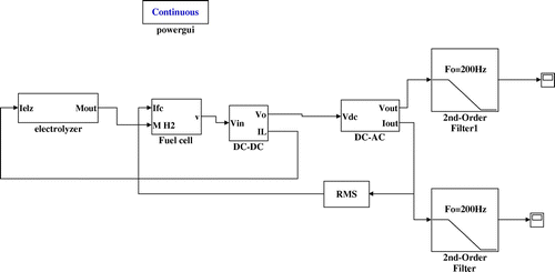
A Simulink model based on the Equations (Equation13(13) –Equation21
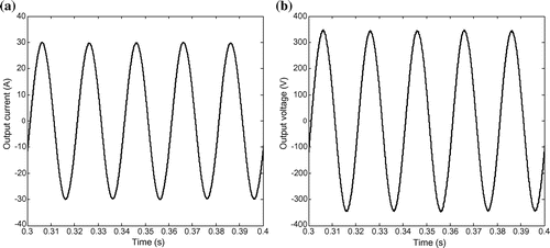
(21) ) of the PEMFC and electrolyser is developed as shown in Figure . The output current and voltage are depicted in Figure (a) and (b). It is clear that the total output power of the FC is 5 kW.
4.4. Battery model
A battery bank is incorporated in this distributed energy system as a backup source for emergency use. The battery bank is used when a sudden load change occurs for a short period of time (approximately 30 minutes or less). It is assumed that the power required for this short period of time is about 30% of the total load. Therefore, a battery bank of 10 batteries connected in series is used. Each battery is of lead-acid type with open-circuit voltage of 12 V and Amper-hour capacity of 12 Ah. The battery voltage during the discharge mode is given by (Tremblay and Dessaint Citation2009).(22)
where Vb is the battery voltage (V), E0is the battery nominal voltage (V), K is the polarisation constant (V/Ah), Q is the battery capacity (Ah), is the actual battery charge (Ah), R is the battery internal resistance (Ω), i is the internal current (A) and i*is the filtered current (A). During the charging phase, the battery voltage is expressed by (14) (Tremblay and Dessaint Citation2009).
(23)
In (21) and (22) the function H(t) represents the hysterisis phenomenon between the charge and the discharge modes of lead-acid type battery and is given by (23)(24)
where A is the exponential-zone amplitude (V), is the exponential-zone time constant, where B is in (Ah)−1 and
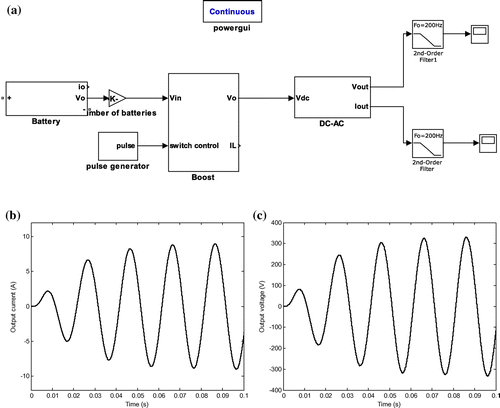
The simulink model shown in Figure (a) is developed based on Equations (Equation21(21) –Equation23
(24) ). Simulation results for output voltage are given in Figure (b) and (c). The total output power of the battery bank is approximately 1.5 kW.
5. Power management system
5.1. Power management system diagram
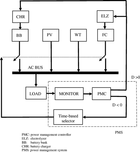
There are four sources of energy that can be utilised to provide the load demand. These sources are connected to a single AC bus. The PV and WT are permanently connected to the bus and the FC and the battery bank are connected to the bus according to the decision signal , where
. When D > 0, the surplus generated power is directed to the electrolyser (ELZ) and the battery bank (BB) and its charging unit (CHR). In the case D < 0, the BB and FC will compensate for the required power. The short duration (30 minutes or less) power deficit will be taken care of by the BB while the long duration (up to six hours) power deficit is supplied by the FC. The block diagram of the overall power management system is shown in Figure (a). The complete block diagram is shown in Figure .
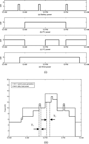
5.2. Discussion of results
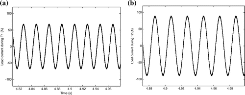
The main sources of electrical power to the stand-alone load (e.g. eco-house) are the PV and the WT subsystems with total generation of 10 kW. In the evening, the FC with the wind turbine becomes the main source of energy with total power of 10 kW. The battery works as back up to provide power for a short period. The power production from each subsystem is presented in Figure (i). The load duration curve (solid line) and the total power production from the DG system (dashed line) are depicted in Figure (ii). The results show that the generated power from the different energy sources is capable to satisfy the load demands during the whole day. The total current at two different loading periods T1 and T2 shown in Figure (ii) are presented in Figure . It is clear that during T1 and T2 the RMS value of load currents are and
, respectively. According to the proposed power management system, the load current
will be supplied by the PV, WT and BB while
will be supplied by the PV, WT and FC.
6. Conclusions
Wind and photovoltaic power generation are two of the most promising renewable energy technologies. Fuel cell systems show great potential due to their fast technology development and many merits, such as high efficiency, zero or low emission (of pollutant gases) and flexible modular structure. In this paper, RES are modelled and simulated to provide the power requirement for an isolated-load. The system sizing is discussed and the overall control and power coordination strategy for the proposed hybrid energy system is presented. In the management scheme, the PV and wind generation subsystems are considered as the main power generation units. The FC subsystem is the backup generation and battery picks up the fast load changes. The electrolyser acts as a dump load utilising any excess power to produce hydrogen for the FC. The simulation model of the hybrid system has been developed using MATLAB/Simulink. Simulation studies are carried out to verify the system performance under different load conditions. The simulation results have been presented and discussed for an eco-house load. The results show that the power flow among the different energy sources satisfy the required load demand.
Disclosure statement
No potential conflict of interest was reported by the authors.
Notes on contributors
Hassan A. Yousef received his BSc (Honor) and MSc Degrees in Electrical Engineering from Alexandria University, Alexandria, Egypt in 1979 and 1983, respectively. He obtained the PhD degree in Electrical and Computer Engineering from University of Pittsburgh, PA, USA in 1989. He spent 15 years in Alexandria University as assistant, associate and Professor, 6 years in Qatar University as associate professor. Now, he is with the Department of Electrical and Computer Engineering, Sultan Qaboos University. He supervised 27 completed MSc theses and 8 completed PhD theses. In 2017, he published with CRC press a book titled Power System Load Frequency Control: Classical and Adaptive Fuzzy Approaches. His research interests include control system analysis and design, nonlinear and adaptive control, and intelligent control applications to power systems.
Abdullah Al-Badi obtained the BSc in Electrical Engineering from SQU, Oman, in 1991. He received the degree of MSc and PhD from UMIST, UK, in 1993 and 1998, respectively. He has published more than 100 papers in many well-known international journals and proceedings of refereed international conferences. He carried out several projects on the effects of AC interference on pipelines, renewable energy and electrical machines. He is a senior member of the Institute of Electrical Engineering and Electronics, IEEE, USA and a consultant in Oman Society of Engineers. He is member of editorial board of two international journals and reviewer of several international journals. He is IEEE program evaluator for Accreditation Board for Engineering and Technology (ABET) and Oman Academic Accreditation Authority (OAAA) Register as External Reviewer. In 2009, he was appointed as a Dean for the Deanship of Admissions and Registration and in February 2014 was appointed as a Dean for the College of Engineering, and he is currently a professor in Electrical & Computer Engineering Department in Sultan Qaboos University.
Alexis Polycarpou received his BE degree in Electrical and Electronic Engineering from the University of the West of England in Bristol, followed by an MSc in Electrical Power systems from the University of Bath. While being a member of the Power Systems and Electronics Research Group of UWE, Bristol, he was employed as a visiting lecturer and received his PhD in Electrical power systems and power quality. He then worked as an international research and development engineer for Siemens AG, Amberg, Germany. He is currently an assistant professor at the Electrical Engineering Department of Frederick University, Cyprus. His research interests include the analysis of power systems, power system stability, protection, power quality and energy efficiency. His research resulted to a number of publications including two books, and a number of journal and conference papers. He is the chairman of young members of the IET Cyprus Network, a member of the IEEE Power Engineering Society, CIGRE, and the Cyprus Scientific and Technical Chamber.
Acknowledgement
The second author would like to acknowledge the Erasmus Mundus SECRET Program for the Research Fellowship and Frederick University Cyprus for providing the research facility.
References
- Agbossou, K., M. Kolhe, J. Hamelin, and T. Bose. 2004. “Performance of a Stand-Alone Renewable Energy System Based on Energy Storage as Hydrogen.” IEEE Transactions on Energy Conversion 19 (3): 633–640.10.1109/TEC.2004.827719
- Al-Badi, A. H. 2012. “Hybrid Energy Systems for Applications in Eco-Houses.” Paper presented at the Asia-Pacific Power and Energy Engineering Conference (APPEEC 2012), Shanghai, China, March 26–28.
- Albadi, M., and E. El-Saadany. 2010. “New Method for Estimating CF of Pitch-regulated Wind Turbines.” Electric Power Systems Research 80 (9): 1182–1188.10.1016/j.epsr.2010.04.001
- Al-Badi, A. H., M. Al-Toobi, S. Al-Harthy, and Z. Al-Hosni. 2011. “Techno-economic Analysis for a Hybrid Stand-alone Power Generation.” Paper presented at the International Conference on Power Electrical Systems (PES), Sousse, Tunisia, March 22–25.
- Al-Badi, A. H., M. H. Al-Badi, A. M. Al-Lawati, and A. S. Malik. 2011. “Economic Perspective for PV Electricity in Oman.” Energy 36 (1): 226–232.10.1016/j.energy.2010.10.047
- Bai, Wenlei, M. Reza Abedi, and Kwang Y. Lee. 2016. “Distributed Generation System Control Strategies with PV and Fuel Cell in Microgrid Operation.” Control Engineering Practice 53: 184–193.10.1016/j.conengprac.2016.02.002
- Bassam, Ameen M., Alexander B. Phillips, Stephen R. Turnock, and Philip A. Wilson. 2016. “An Improved Energy Management Strategy for a Hybrid Fuel Cell/Battery Passenger Vessel.” International Journal of Hydrogen Energy 41 (47): 22453–22464.10.1016/j.ijhydene.2016.08.049
- Colson, C. M., and M. H. Nehrir. 2009. “A Review of Challenges to Real-Time Power Management of Microgrids”, Paper presented at the general meeting for the IEEE Power and Energy Society, PES’09, Calgary, Alberta, Canada, July 26–30.
- Dash, Vaishalee, and Prabodh Bajpai. 2015. “Power Management Control Strategy for a Stand-alone solar Photovoltaic-fuel Cell–Battery Hybrid System.” Sustainable Energy Technologies and Assessments 9: 68–80.10.1016/j.seta.2014.10.001
- Dursun, Erkan, and Osman Kilic. 2012. “Comparative Evaluation of Different Power Management Strategies of a Stand-Alone PV/ Wind/ PEMFC Hybrid Power System.” Electrical Power and Energy Systems 34 (1): 81–89.10.1016/j.ijepes.2011.08.025
- Hajizadeh, Amin, and Masoud Aliakbar Golka. 2007. “Intelligent Power Management Strategy of Hybrid Distributed Generation System.” Electrical Power and Energy Systems 29 (10): 783–795.10.1016/j.ijepes.2007.06.025
- Hu, Sheng, Xinchun Lin, Yong Kang, and Xudong Zou. 2011. “An Improved Low-voltage Ride-Through Control Strategy of Doubly Fed Induction Generator During Grid Faults.” IEEE Transactions on Power Electronics 26 (12): 3653–3665.10.1109/TPEL.2011.2161776
- Ipsakisa, D., S. Voutetakisa, P. Seferlisa, F. Stergiopoulosa, and C. Elmasidesb. 2009. “Power Management Strategies for a Stand-alone Power System using Renewable Energy Sources and Hydrogen Storage.” International Journal of Hydrogen Energy 34: 7081–7095.10.1016/j.ijhydene.2008.06.051
- Lagorse, Jeremy, Damien Paire, and Abdellatif Miraoui. 2010. “A Multi-agent System for Energy Management of Distributed Power Sources.” Renewable Energy 35 (1): 174–182.10.1016/j.renene.2009.02.029
- Larminie, James, and Andrew Dicks. 2003. Fuel Cell Systems Explained. Hoboken, NJ: Wiley.10.1002/9781118878330
- Li, Qi, Weirong Chen, Zhixiang Liu, Ming Li, and Lei Ma. 2015. “Development of Energy Management System Based on a Power Sharing Strategy for a Fuel Cell-battery-supercapacitor Hybrid Tramway.” Journal of Power Sources 279: 267–280.10.1016/j.jpowsour.2014.12.042
- Lopez, J., P. Sanchis, X. Roboam, and L. Marroyo. 2007. “Dynamic Behaviour of the Doubly-fed Induction Generator During Three-phase Voltage Dips.” IEEE Transactions on Energy Conversion 22 (3): 709–717.10.1109/TEC.2006.878241
- Muyeen, S. M., J. Tamura, and T. Murata. 2009. Stability Augmentation of a Grid-connected Wind Farm. Verlag London: Springer.
- Nehrir, M., and C. Wang. 2009. Modeling and Control of Fuel Cells: Distributed Generation Applications. New Jersey: Wiley-IEEE press.10.1109/9780470443569
- Soto, W. D., S. Klein, and W. Beckman. 2006. “Improvement and Validation of a Model for Photovoltaic Array Performance.” Solar Energy 80 (1): 78–88.10.1016/j.solener.2005.06.010
- Tremblay, Olivier, and Louis-A., Dessaint. 2009. “Experimental Validation of a Battery Dynamic Model for EV Applications.” World Electric Vehicle Journal 3: 289–298.
- Wang, Caisheng. 2006. Modelling and Control of Hybrid Wind/Photovoltaic/Fuel Cell Distributed Generation Systems. Ph.D. diss., Montana State University.
- Wang, C., and M. Nehrir. 2008. “Power Management of a Stand-Alone Wind/Photovoltaic/Fuel Cell Energy System.” IEEE Transactions on Energy Conversion 23(3): 957:968.10.1109/TEC.2007.914200
- Zhou, K., J. A. Ferreira, and S. W. H. de Haan. 2008. “Optimal Energy Management Strategy and System Sizing Method for Stand-alone Photovoltaic-hydrogen Systems.” International Journal of Hydrogen Energy 33 (2): 477–489.10.1016/j.ijhydene.2007.09.027

