Abstract
This paper presents a H∞ loop-shaping controller for controlling dc-link voltage by regulating the switching signal of the inverter associated with a grid-connected single-phase photovoltaic system. To facilitate a robust control design, state-space realisation of the system model is made with uncertainties represented by linear fractional transformation. The controller is achieved through H∞ synthesis followed by obtaining desired loop shapes through the choice of the proper weighting functions. The controller order is reduced by Henkel-norm method for facilitating its practical implementation. Controller performance is evaluated through carrying out simulations on MATLAB/Simulink platform under standard and changing atmospheric conditions, and fault condition.
1. Introduction
Renewable energy has received an increasing attention all over the world due to global concern about atmospheric disorder and sustainable energy demand. The photovoltaic (PV) system has become one of the most prominent energy sources due to their environment-friendly operation. Technological advancements have resulted in battery cost reduction. Governments around the world also have come forward with their policies (e.g. Feed-in-tariff). These factors altogether have promoted increasing number of PV installation (Eftekharnejad et al. Citation2013). However, the intermittent PV generation fluctuates with weather fluctuations, which in turn may result in frequency fluctuations and voltage flickers (Chowdhury, Hosseinzadeh, and Shen Citation2012). Thus, it is justified to have efficient control schemes to deliver maximum power during such unfavourable situations.
A stable operation can be conserved under disturbances or an external fault within the system with the employment of proper controllers in the PV system. This can be accomplished by means of regulating the switching signal of the inverter with the proper control signals from the controllers. Maximum power point tracking (MPPT) techniques usually perform these tasks whose details can be found in (Barchowsky et al. Citation2012; Guan-Chyun et al. Citation2013). Two most familiar MPPT techniques used in PV systems are perturb and observe (PO) method and incremental conductance method (Banu, Beniuga, and Istrate Citation2013; Sera et al. Citation2013). In PO method, the derivative of power (dp) and the derivative of voltage (dv) diagnose the movement of the operating points. Change in reference voltage is positive if the ratio of dp and dv is positive, and vice versa (Liu and Liu Citation2009). Incremental conductance and instantaneous conductance of the PV arrays are collated in the incremental conductance method for achieving MPPT (Bangyin et al. Citation2007).
There are several controllers such as proportional integral (PI) controllers, hysteresis controllers, predictive controllers, sliding mode controllers, intelligent controllers and feedback linearisation controllers that can assist in stable operation of PV systems by regulating the system parameters to follow the reference points. A PI controller is proposed to conserve ideal shape of output current and to have fast dynamic responses under extreme weather fluctuations in (Krommydas and Alexandridis Citation2013). PI controllers are extremely difficult to use during such fluctuating weather due to the requirement of continuous gain tuning (Dash and Kazerani Citation2011). The hysteresis controller is quick to respond but possesses a non-constant switching frequency (Dubey Citation2014). The predictive controller trounces the limitation non-constant switching frequency but it cannot continually adopt with weather fluctuations (Kotsopoulos, Duarte, and Am Hendrix Citation2001). The sliding mode controller provides a robust tracking against the model uncertainties of the PV system, but the design requires a difficult task of selection of a time-varying surface while the system stays confined to the sliding surface (Cabal et al. Citation2014). Intelligent control techniques such as neural network, genetic algorithm, fuzzy logic, are also used for MPPT (Dahmane et al. Citation2013; Mohd Zainuri et al. Citation2014; Singh, Shahani, and Verma Citation2014), but these are not as efficient as the model-based controllers. Moreover, these methods lengthen the search space significantly and are unable to capture the accurate system dynamics. PV systems are non-linear due to the unpredictability of sunlight and the switching functions of the inverters. Feedback linearisation is a model-based non-linear control technique that overcomes inherent non-linearities and thus enhances the dynamic stability. Exact feedback linearisation technique transforms a non-linear system into a fully linear one (Isidori Citation1989; Slotine and Li Citation1991; Delfino et al. Citation2012) while partial feedback linearising technique comes with an easier way of control implementation transforming a non-linear system into a partially linear one (Mahmud, Pota, and Hossain Citation2014; Mahmud et al. Citation2014). Partial feedback linearising technique does not fully require ambiguous, complex and non-linear dynamics of the PV system. But this technique introduces an autonomous system whose dynamics are needed to be stable.
Nevertheless, none of the above-mentioned control strategies that can explicitly dictate the desired degree of robustness in the design goal in advance, which hinders the robustness under model uncertainty. The specifications such as tracking performance, bandwidth and robustness against model uncertainty are expressed in H∞ control design as constraints on the gain responses of the closed-loop transfer functions. By incorporating design goals of tracking performance and desired robustness into the choice of the weighting functions, desired loop shapes (ideal profiles of the closed-loop transfer functions) may result once a solution is admitted for the corresponding standard control problem. Since the robustness requirement is embedded in the selection of the weighting functions, the loop-shaping control strategy can be employed as a means to find the robust controller to sustain prescribed model uncertainty as large as possible.
H∞ controller has a history of successful implementation in inverters for various applications (Tzann-Shin, Chiang, and Jhy-Ming Citation2001; Willmann et al. Citation2007; Lim et al. Citation2014; Chowdhury, Mahmud, and Oo Citation2015b), which pioneered the authors to design a new H∞ loop-shaping controller for controlling dc-link voltage by regulating the switching signal of the inverter associated with a grid-connected single-phase PV system. For achieving a supreme robust performance, state-space realisation of the system model is made with uncertainties represented by linear fractional transformation (LFT).
The rest of the paper is organised as follows. The mathematical model of a grid-connected single-phase PV system and LFT representation of the structured uncertainties with the system are described in Sections 2 and 3, respectively. Section 4 presents the brief overview and design methodology of a H∞ loop-shaping controller for a grid-connected single-phase PV system. Section 5 analyses the simulation results to evaluate performance of the proposed controller under standard and changing atmospheric conditions, and fault incident. The concluding remarks are made in Section 6.
2. Grid-connected single-phase photovoltaic system model
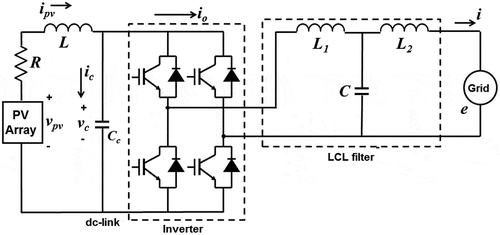
shows the schematic diagram of a grid-connected single-phase photovoltaic (PV) system. The PV system comprises a PV array, a PV line (with resistance R and inductance L), a dc-link capacitor (with capacitance C c ) and a single-phase inverter connected to the grid (with current i and voltage e) through an LCL filter (having inductances L 1 and L 2, and capacitance C). The main objective in this paper is to control the dc-link voltage by means of appropriate regulation of the inverter switches.
A PV cell is a simple p–n junction diode that produces electricity from irradiation. A number of PV cells are connected together in series to form a PV module in order to compensate low voltage from a single cell. To obtain the required voltage and power, a number of modules are connected in parallel to form a PV array. The PV array current i pv thus becomes
We assume that the switching frequency of the pulse-width modulator (PWM) is much higher than the frequency of the modulating signal u. Then the following relationship can be derived for the grid-connected single-phase PV system by applying Kirchhoff’s voltage law and Kirchhoff’s current law as:
Assuming C to be constant, derivative of Equation (3) gives,
From Equations (2) and (4), we have the following second-order differential equation:
where
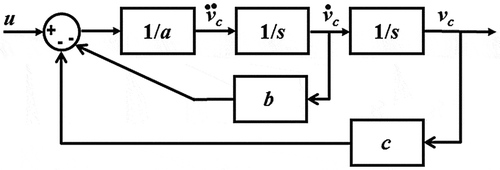
A block diagram of the PV system is shown in .
3. Model uncertainty and LFT
The parameters L, C c and R in a grid-connected single-phase PV system are assumed to be non-variable with time to derive Equation (9). In reality, these parameters alter with changing operating conditions. As a result, the physical parameters a, b and c in Equation (9) are not known exactly, rather assumed within certain known intervals. Thus, these can be written as:
We replace three constant blocks in with blocks in terms of the nominal values, uncertainty level and range of the parameters a, b and c. The quantity 1/a, b and c are represented as an LFT in δ a , δ b and δ c , respectively, as:
with
Similarly, we have,
and
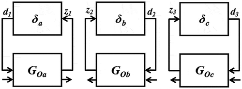
shows an upper LFT representation of uncertainties δ a , δ b and δ c affecting the nominal plants G oa , G ob and G oc .
Relating all inputs to the corresponding outputs around these uncertain parameters, we obtain
where d 1, d 2 and d 3 are the inputs and z 1, z 2 and z 3 are the outputs of the uncertainty blocks δ a , δ b and δ c , respectively.
We define two states x 1 and x 2 as:
We have then the following final equations as:
The final equation governing the system dynamic behaviour is given by:
and
Equation (6) defines the nominal plant G
O
for a grid-connected single-phase PV system, where is the deviation of v
c
from the reference value. The realisation of G
O
can be made by the state-space matrices (
) in the following manner:
where
On the other hand, Equation (7) defines the diagonal uncertainty matrix Δ = diag(δ a , δ b , δ c ). The uncertain behaviour of the PV system can be described as y = F U (G O ,Δ)u with uncertainty Δ. Since the uncertainty has a fixed structure, it is termed as structured uncertainty.
4. H∞ loop-shaping control methodology
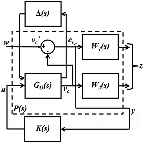
shows the proposed H∞ control configuration with weighting functions where G O (s) is the nominal plant with perturbation Δ(s), K(s) is the controller to be designed and W 1(s) and W 2(s) are the weighting functions for tracking error performance and robust performance, respectively. The nominal plant and the weighting functions are combined to form a closed-loop system of an augmented plant P(s) in the following manner:
If we have state-space realisations for G O , W 1 and W 2 as:
then, we can derive the state-space realisation for P as:
In our design, , and z is achieved through selection of weighting functions W
1 and W
2. The design objective of H∞ loop-shaping control is to deriving a linear output feedback control law
u = K(s)y
that gives the minimisation of the function F
l
(P, K). This is accomplished by synthesising the stabilising controller K(s) so that the H∞ gain from w to z is less than one (i.e. Shuitao et al. Citation2011; Chowdhury, Mahmud, and Oo Citation2015a),
Once the H∞-norm bound (Equation 9) is achieved, a H∞ synthesis is conducted for shaping S(s) and T(s) by properly selecting their respective weighting functions W 1 and W 2. W 1 is typically chosen such that we have high gain inside the desired control bandwidth for good disturbance attenuation (in other word, tracking performance) and W 2 is selected to attain high gain outside the desired control bandwidth for good stability margin (in other word, robustness).
In summary, the H∞ loop-shaping design in this paper involves
making the proper selection of the weighting functions W 1 and W 2,
performing the synthesis of the controller and
reducing the order of K(s) provided that it performs almost similar to the original one.
4.1. Proper weighting function selection
Weighting functions are to be selected considering frequency characteristics and relative weights of different signals. Weighting functions W 1 and W 2 must meet three following criteria so that minimum tracking error and robustness are achieved and constraint (10) is reached.
Criterion 1: The condition must be satisfied that corresponds to high gain of W
1(s) at only the vicinity of line frequency and vice versa for all other frequency. W
1 is initially chosen as:
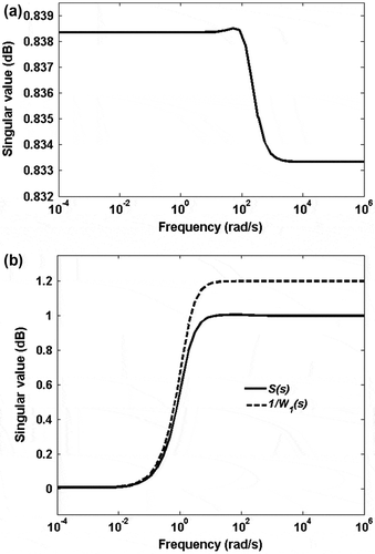
(a) shows the singular value of the closed loop of the grid-connected single-phase PV system. We observe that the H∞ norm of the closed-loop system is less than 1, which ensures that the condition is satisfied. In addition, this is verified by comparing the sensitivity function of the closed-loop system with inverse of W 1 in (b), which shows that singular value of S lies below that of 1/W 1.
Figure 5. Achievement of Criterion 1: (a) Singular value of the closed loop of the grid-connected single-phase PV system and (b) Singular values of S(s) and 1/W 1(s).
Criterion 2: The condition must be satisfied that correspond to the fact that W
2(s) must bound the worst-case uncertainty spectrum from above. W
2 is initially chosen as:
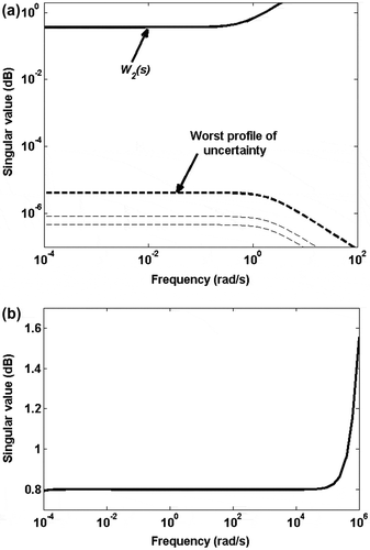
In (a), several uncertainty profiles are drawn and it is well observed that the singular value of W 2 lies well above that of the worst profile of Δ. This ensures that the condition is satisfied. Δ gives the worst profile when inductance L is maximum and resistance R is minimum.
Figure 6. Achievement of Criterion 2: (a) Singular values of W 2(s) and the worst-case profile of uncertainty and (b) Robust performance of the controller.
For further justification of meeting criterion 2, the robust performance of the closed-loop grid-connected single-phase PV system is tested with the controller by means of the μ-analysis since the uncertainty considered in this paper is structured (Gu, Petkov, and Konstantinov Citation2005). For this purpose, the parametric uncertainties are assumed to be real and 1% complex uncertainty is included for better convergence of the algorithm.
(b) shows that the μ curve for the robust performance has the value of 0.8 for most of the considered frequency range. It means that the structured uncertainties with norm less than 1/0.8 are allowable, i.e. the grid-connected single-phase PV system maintains the robust performance with the controller for . However, the controller fails to show robust performance (since the μ curve exceeds the value 1) when the frequency is well above5 × 105 rad/s.
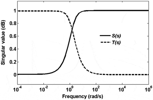
Criterion 3: The 0-dB crossover frequency of W 1 must be sufficiently below the 0-dB crossover frequency of 1/W 2, which is affirmed by the constraint (10). We have achieved this constraint in our controller design, which is shown in .
4.2. Controller synthesis
The next step after selecting proper weighting functions is to conduct synthesis process to transform the design problem into a standard H∞ control problem so that H∞-norm bound is achieved. This is accomplished in this paper by the Glover-Doyle algorithm (Glover and Doyle Citation1988) using hinfsyn function of Robust Control Toolbox from MATLAB. The algorithm solves a family of stabilising controllers such that F l (P, K)≤ γ and find the minimum possible value of γ for which this equation has a solution. For γ iteration, the interval is chosen between 0.1 and 10 with tolerance of 0.001. The current value of γ is either accepted or rejected at each iteration. When the iteration procedure succeeds, the minimum γ value is given. In our simulation, the achievable minimum value of γ is 0.9769.
The synthesis results in a higher order controller as follows:
One point to note is that the following conditions must be satisfied for synthesising process:
G O (s), W 1(s) and W 2(s) must be proper,
W 1(s) and W 2(s) must be stable and
G O (s) must be stabilisable and detectable.
4.3. Controller order reduction
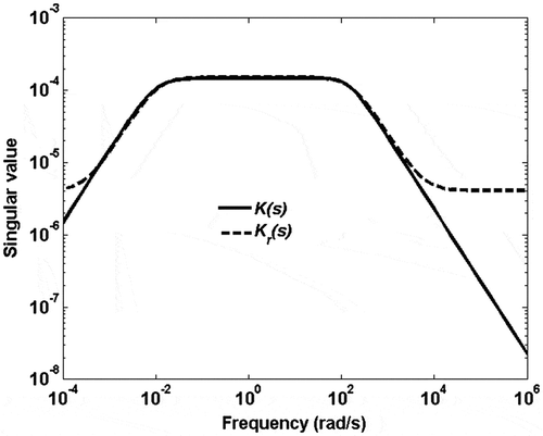
High-order controller is somewhat unrealistic to implement since the sampling frequency is usually limited to the switching frequency. In order to facilitate practical implementation of the controller, it is subjected to model order reduction. This is accomplished in this paper by the optimal Hankel-norm method (Dehghani and Yazdanpanah Citation2005) using hankmr function in MATLAB. This method efficiently reduces the order of the controller by computing the error bound on the infinity norm with the help of Hankel singular values. We have the final H∞ controller K r (s) as follows:
The singular values of the original controller K(s) and the reduced controller K r (s) are shown in . The reduced controller shows almost the similar performance as the original one in the frequency region: 10−3 rad/s ≤ f ≤ 104 rad/s while it provides a smaller attenuation than that of the original one within the rest of the frequency regions.
5. Controller performance evaluation
The main purpose of the control action is to extract maximum power (3.5 kW) power from the grid-connected single-phase PV system through MPPT to supply to the grid. This can be done by regulating the inverter switches through the proper control scheme.
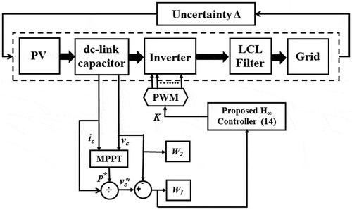
The implementation block diagram of the designed H∞ loop shaping control scheme is shown in . The reference value of the dc-link voltage, is generated with the help of the reference power from photovoltaic system, P* and filter capacitor current, i
c
using the following equation (Mahmud, Pota, and Hossain Citation2014):
The error signal from the dc-link voltage () is used as control input to derive the control law (14). Finally, the control input is implemented through the inverter switches using a pulse-width modulation (PWM) technique with a switching frequency of 3.78 kHz. The weighting function, W
1 is tuned to minimise (
) and W
2 to improve robust performance of the controller.
To evaluate the performance of the controller, Simulations are carried out on a simple grid-connected single-phase PV system with parameters given in on MATLAB/Simulink platform under standard and changing atmospheric conditions, and fault incident.
Table 1. Grid-connected single-phase PV system parameters.
5.1. Standard atmospheric conditions
The simulation is first carried out under standard atmospheric conditions, where solar irradiation and the temperature of the system are considered as 1000 Wm−2 and 298 K, respectively. Under such condition, the output dc power from the grid-connected single-phase PV system is depicted in (a). From the figure, a small fluctuation with a standard deviation of 0.0118 W in the dc power is observed within the time range between 0.2 and 0.6 s. This occurs due to non-linear characteristics of the PV system. Analysing the grid voltage and current is also an essential part of the controller performance evaluation. The grid voltage (dotted line) and current (solid line) are shown in (b) with the proposed control scheme. It is seen from the figure that the voltage and current are in phase to each other, which indicates that the grid-connected single-phase PV system maintains unity power factor operation.
5.2. Changing atmospheric conditions
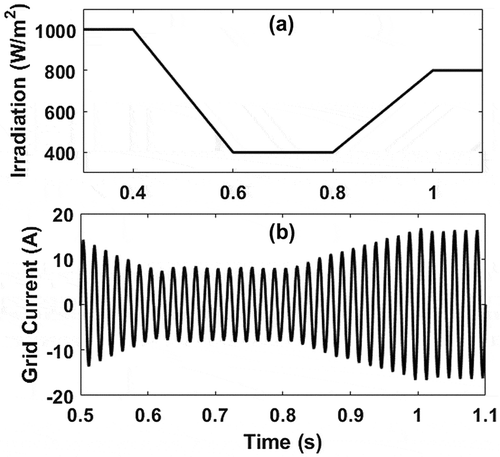
Atmospheric conditions continually change in a practical PV system due to variations in cell working temperature, as well as in solar irradiance. The impact of changes in atmospheric conditions is demonstrated through the variation of solar irradiation as shown in (a). The figure shows that the solar irradiation ramps down due to partial shading of the PV system and reaches to 400 W/m2 at 0.6 s and consequently ramps up again to 800 W/m2 at 1 s. The temperature of the system is held constant to 298 K throughout the simulation. The performance of the controller is demonstrated under this condition in (b), where current delivered to the grid changes according to new settings of MPPT. This result exhibits that the controller successfully controls the input to the inverter switches to set new MPPTs in accordance with the change in atmospheric condition (i.e. solar irradiation).
5.3. Fault condition
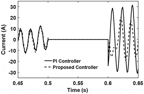
Any abnormal condition, such as fault incident may change the PV system topology and instability may prevail. In this section, the performance of the proposed controller is evaluated in restoring post-fault variables of the system to their respective nominal values and thus maintaining stability. For the analysis, a line-to-ground fault is initiated at the grid at t = 0.5 s, which is cleared after 100 ms. shows that there is no current flow (i.e. no power exchange) between the PV units and the grid. An undamped oscillation is also observed with the use of the PI controller while the proposed controller can effectively damp the post-fault system oscillation to maintain system stability.
6. Conclusions
A H∞ loop-shaping control scheme is presented to enhance the dynamic performance of a grid-connected single-phase photovoltaic (PV) system with changes in atmospheric conditions and fault incident. The PV model is represented in terms of state-space realisation with uncertainties through LFT. The controller is achieved through H∞ synthesis followed by obtaining desired loop shapes through the choice of the proper weighting functions. From the simulation results, it is clear that the controller performs satisfactorily under different atmospheric conditions and fault incident. For example, the controller helps the PV operation at unity power factor while it successfully controls the input to the inverter switches to deliver power to the grid at the maximum power point in accordance with the change in atmospheric condition. These results establish that the proposed controller is highly robust against atmospheric uncertainties. The controller also helps to maintain system stability followed by fault. Future works will be emphasised on extending the proposed method by considering some mismatches within the PV model and implementing hardware-in-loop simulation.
Disclosure statement
No potential conflict of interest was reported by the authors.
Notes on contributors
Md Ayaz Chowdhury received the Bachelor’s (Hons.) degree in electrical and electronic engineering from the Islamic University of Technology, Dhaka, Bangladesh, in 2007, and the PhD degree in electrical engineering from the Swinburne University of Technology, Melbourne, Vic, Australia, in 2013. Earlier, he was a lecturer with International Islamic University Chittagong, Bangladesh, from 2008 to 2009; with Swinburne University of Technology, Malaysia, from 2014 to 2015; and with Monash University, Malaysia, from 2015 to 2017. He is currently a consulting engineer on Power Systems at GHD, Australia. He has published about 30 scientific articles in the form of book chapter, journal and conference proceedings. His research interests include power system stability and control, renewable energy, microgrid/smart grid, and energy storage. He is a chartered engineer and member of IEEE.
Saad Bin A. Kashem received the BSc degree in electrical and electronic engineering from East West University, Bangladesh in 2009, and received the PhD degree from Swinburne University of Technology, Australia in 2013. At present, he is working as a Computer Skills Faculty at Qatar Armed Forces – Academic Bridge Programme, Qatar Foundation. Before, he worked with Faculty of Engineering, Computing and Science in Swinburne University of Technology, Malaysia. He has over 10 years’ experience in both industry and academia. He is a professional member of Institution of Engineering and Technology, UK (IET), Institute of Electrical and Electronic Engineers (IEEE), IEEE Robotics and Automation Society, and International Association of Engineers (IAENG). He has reviewed many national and international reputed Journals and Conferences. His research interests include vehicle dynamic, electric vehicle, renewable energy systems, intelligent and autonomous control, robotics, non-linear control theory and applications.
References
- Bangyin, Liu, Duan Shanxu, Liu Fei, and Xu Pengwei. 2007. “Analysis and Improvement of Maximum Power Point Tracking Algorithm Based on Incremental Conductance Method for Photovoltaic Array.” Paper presented at 7th International Conference on the Power Electronics and Drive Systems. PEDS ‘07, Bangkok, November 27–30.
- Banu, I. V., R. Beniuga, and M. Istrate. 2013. “Comparative Analysis of the Perturb-and-Observe and Incremental Conductance MPPT Methods.” Paper presented at 8th International Symposium on the Advanced Topics in Electrical Engineering (ATEE), Bucharest, May 23–25.
- Barchowsky, A., J. P. Parvin, G. F. Reed, M. J. Korytowski, and B. M. Grainger. 2012. “A Comparative Study of MPPT Methods for Distributed Photovoltaic Generation.” Paper presented at the Innovative Smart Grid Technologies (ISGT), IEEE PES, Washington, January 16–20.
- Cabal, C., L. Martínez-Salamero, L. Séguier, C. Alonso, and F. Guinjoan. 2014. “Maximum Power Point Tracking Based on Slidingmode Control for Output-Series Connected Converters in Photovoltaic Systems.” IET Power Electronics 7 (4): 914–923. doi:10.1049/iet-pel.2013.0348.
- Chowdhury, M. A., and M. A. Mahmud. 2014. “Characteristics Evaluation of a H∞ Loop-Shaping Controller for a Single-Phase PV System.” Paper presented at the 2014 IEEE PES Asia-Pacific Power and Energy Engineering Conference (APPEEC), Hong Kong, December 7–10.
- Chowdhury, M. A., N. Hosseinzadeh, and W. X. Shen. 2012. “Smoothing Wind Power Fluctuations by Fuzzy Logic Pitch Angle Controller.” Renewable Energy 38 (1): 224–233.10.1016/j.renene.2011.07.034
- Chowdhury, M. A., M. A. Mahmud, and A. M. T. Oo. 2015a. “Characteristics Evaluation of a Mu-Synthesis H∞ Controller for a Grid-connected Three-phase Photovoltaic System.” Paper presented at the Smart Grid Technologies – Asia (ISGT ASIA), 2015 IEEE Innovative, Bangkok, November 3–6.
- Chowdhury, M. A., M. A. Mahmud, and A. M. T. Oo. 2015b. “Characteristics Evaluation of an LMI-Synthesis H∞ Controller for a Superconducting Magnetic Energy Systems Applied in Power Systems.” Paper presented at the Smart Grid Technologies – Asia (ISGT ASIA), 2015 IEEE Innovative, Bangkok, November 3–6.
- Dahmane, M., J. Bosche, A. El-Hajjaji, and X. Pierre. 2013. “MPPT for Photovoltaic Conversion Systems Using Genetic Algorithm and Robust Control.” Paper presented at the American Control Conference (ACC), Washington, June 17–19.
- Dash, P. P., and M. Kazerani. 2011. “Dynamic Modeling and Performance Analysis of a Grid-connected Current-Source Inverter-based Photovoltaic System.” IEEE Transactions on Sustainable Energy 2 (4): 443–450. doi:10.1109/tste.2011.2149551.
- Dehghani, M., and M. J. Yazdanpanah. 2005. “Model Reduction Based on the Frequency Weighted Hankel-Norm Using Genetic Algorithm and Its Application to the Power Systems.” Paper Presented at the Control Applications, 2005. CCA 2005. Proceedings of 2005 IEEE Conference on, Toronto, August 28–31.
- Delfino, F., G. B. Denegri, M. Invernizzi, and R. Procopio. 2012. “Feedback Linearisation Oriented Approach to Q–V Control of Grid Connected Photovoltaic Units.” IET Renewable Power Generation 6 (5): 324–339. doi:10.1049/iet-rpg.2011.0075.
- Dubey, R. 2014. “Neural Network MPPT Control Scheme with Hysteresis Current Controlled Inverter for Photovoltaic System.” Paper presented at Recent Advances in the Engineering and Computational Sciences (RAECS), March 6–8.
- Eftekharnejad, S., V. Vittal, G. T. Heydt, B. Keel, and J. Loehr. 2013. “Impact of Increased Penetration of Photovoltaic Generation on Power Systems.” IEEE Transactions on Power Systems 28 (2): 893–901. doi:10.1109/tpwrs.2012.2216294.
- Glover, Keith, and J. C. Doyle. 1988. “State-space Formulae for All Stabilizing Controllers that Satisfy an H∞ Norm Bound and Relations to Risk Sensitivity.” Systems & Control Letters 11: 167–172. doi:10.1109/9.29425.
- Gu, D. W., P. Petkov, and M. M. Konstantinov. 2005. Robust Control Design with MATLAB. London: Springer-Verlag.
- Guan-Chyun, Hsieh, I. Hsieh Hung, Tsai Cheng-Yuan, and Wang Chi-Hao. 2013. “Photovoltaic Power-Increment-Aided Incremental-Conductance MPPT with Two-phased Tracking.” IEEE Transactions on Power Electronics 28 (6): 2895–2911. doi:10.1109/tpel.2012.2227279.
- Isidori, A. 1989. Nonlinear Control Systems. Edited by. 2nd ed. Berlin: Springer-Verlag.10.1007/978-3-662-02581-9
- Kotsopoulos, A., J. L. Duarte, and M. Am Hendrix. 2001. “A Predictive Control Scheme for DC Voltage and AC Current in Grid-connected Photovoltaic Inverters with Minimum DC Link Capacitance.” Paper presented at the Industrial Electronics Society, 2001. IECON ‘01. The 27th Annual Conference of the IEEE, Denver, November 29–December 02.
- Krommydas, K. F., and A. T. Alexandridis. 2013. “A New Design Approach of Stable Nonlinear PI Controllers for Stand-Alone Photovoltaic Systems.” Paper presented at the Industrial Electronics Society, IECON 2013 – 39th Annual Conference of the IEEE, Vienna, November 10–13.
- Lim, Jae Sik, Changreung Park, Jungho Han, and Y. I. Lee. 2014. “Robust Tracking Control of a Three-phase DC–AC Inverter for UPS Applications.” IEEE Transactions on Industrial Electronics 61 (8): 4142–4151. doi:10.1109/tie.2013.2284155.
- Liu, Chun-xia, and Li-qun Liu. 2009. “An Improved Perturbation and Observation MPPT Method of Photovoltaic Generate System.” Paper presented at 4th IEEE Conference on the Industrial Electronics and Applications, 2009. ICIEA 2009, Xi’an, May 25–27.
- Mahmud, M. A., H. R. Pota, and M. J. Hossain. 2014. “Nonlinear Current Control Scheme for a Single-phase Grid-connected Photovoltaic System.” IEEE Transactions on Sustainable Energy 5 (1): 218–227. doi:10.1109/tste.2013.2279884.
- Mahmud, M. A., H. R. Pota, M. J. Hossain, and N. K. Roy. 2014. “Robust Partial Feedback Linearizing Stabilization Scheme for Three-phase Grid-connected Photovoltaic Systems.” IEEE Journal of Photovoltaics 4 (1): 423–431. doi:10.1109/jphotov.2013.2281721.
- Mohd Zainuri, M. A. A., M. A. Mohd Radzi, A. C. Soh, and N. A. Rahim. 2014. “Development of Adaptive Perturb and Observe-Fuzzy Control Maximum Power Point Tracking for Photovoltaic Boost DC-DC Converter.” IET Renewable Power Generation 8 (2): 183–194. doi:10.1049/iet-rpg.2012.0362.
- Sera, D., L. Mathe, T. Kerekes, S. V. Spataru, and R. Teodorescu. 2013. “On the Perturb-and-Observe and Incremental Conductance MPPT Methods for PV Systems.” IEEE Journal of Photovoltaics 3 (3): 1070–1078. doi:10.1109/jphotov.2013.2261118.
- Shuitao, Yang, Lei Qin, F. Z. Peng, and Qian Zhaoming. 2011. “A Robust Control Scheme for Grid-connected Voltage-Source Inverters.” IEEE Transactions on Industrial Electronics 58 (1): 202–212. doi:10.1109/tie.2010.2045998.
- Singh, B., D. T. Shahani, and A. K. Verma. 2014. “Neural Network Controlled Grid Interfaced Solar Photovoltaic Power Generation.” IET Power Electronics 7 (3): 614–626. doi:10.1049/iet-pel.2013.0166.
- Slotine, J. J. E., and W. Li. 1991. Applied Nonlinear Control. Upper Saddle River, NJ: Prentice-Hall.
- Tzann-Shin, Lee, S. J. Chiang, and Chang Jhy-Ming. 2001. “H∞ Loop-Shaping Controller Designs for the Single-phase UPS Inverters.” IEEE Transactions on Power Electronics 16 (4): 473–481. doi:10.1109/63.931050.
- Willmann, G., D. F. Coutinho, L. F. A. Pereira, and F. B. Libano. 2007. “Multiple-loop H-infinity Control Design for Uninterruptible Power Supplies.” IEEE Transactions on Industrial Electronics 54 (3): 1591–1602. doi:10.1109/tie.2007.894721.

![Figure 10. Response from grid-connected single-phase PV system during standard atmospheric condition: (a) output dc power (in Watt) and (b) grid voltage (in Volt) [dashed line] and grid current (in Ampere) [solid line].](/cms/asset/340aeff1-aca7-4b47-af9d-45830a527eab/tsue_a_1444680_f0010_b.gif)
