
 ?Mathematical formulae have been encoded as MathML and are displayed in this HTML version using MathJax in order to improve their display. Uncheck the box to turn MathJax off. This feature requires Javascript. Click on a formula to zoom.
ABSTRACT
This paper presents an experimental investigation of heat transfer and friction factor in a rectangular duct with discrete V-rib integrated with staggered elements. The Reynolds number (Re) of 3000–12,000, ratio of staggered element size to rib height (r/e) of 2–5.5, relative roughness pitch (p/e) of 12, relative roughness height (e/Dh) of 0.045, flow angle of attack (α) of 60°, relative gap width (g/e) of 1, relative staggered element position (p’/p) of 0.65 and number of gaps (Ng) of 6. The maximum augmentation in Stanton number is 1.90 times over the smooth duct and maximum thermal efficiency is obtained 86% corresponding to ratio of staggered element size to rib height (r/e) of 3.5.
1. Introduction
The economic growth of our country is powerfully affected by its energy utilisation. With the raise in population, energy need is enhancing day by day. Energy production by utilising fossil fuels is constantly damaging our environment. To build our environment clean utilisation of renewable energy resources is to be enhanced. The renewable resources are sufficient in nature and usable in broad range. Solar energy is greatest bountiful and assuring substitute. At the present time, there are so many ways to use solar energy and convert it into thermal energy. But the acknowledgement of solar energy technology depends on its efficiency and cost-effectiveness with some other factors (Sharma, Bharadwaj, and Varun Citation2017). Efficiency of solar air heater (SAH) duct is poor due to laminar sub-layer development. The main application of SAH is drying of crops and space heating, etc. The use of artificial roughness on absorber surface is useful and easy technique to augment convective heat transfer coefficient of air flowing inside the duct. It is due to turbulence created by artificial roughness element on the absorber surface of roughened duct breaks the laminar sub-layer. But artificial roughness also enhances the friction losses and leads to more power needed by blower for airflow. The important parameters that effect on performance of SAH duct are roughness pitch, height and flow angle of attack. Many experimental studies have been done on SAH duct with different forms of artificial roughness on absorber surface for the maximum enhancement in heat transfer and minimum frictional losses (Varun et al. Citation2009; Bharadwaj et al. Citation2017; Singh et al. Citation2015; Chaube, Sahoo, and Solanki Citation2006; Gupta and Kaushik Citation2009a; Kumar, Saini, and Saini Citation2012).
Literature survey indicates the first artificial roughness geometry reported in the form of transverse rib (Prasad and Mullick Citation1983; Prasad and Saini Citation1988; Gupta, Solanki, and Saini Citation1993; Verma and Prasad Citation2000). Transverse geometry was redesigned as discrete transverse later by Sahu and Bhagoria (Citation2005). From further studies, it is examined that continuous inclined rib roughness gives better performance as compared to transverse continuous rib due to creation of two counters rotating secondary flow cell results enhance heat transfer (Gupta, Solanki, and Saini Citation1997). Continuous V-rib (Momin, Saini, and Solanki Citation2002; Karwa Citation2003), continuous arc-shaped (Saini and Saini Citation2008), W-shaped rib roughness (Lanjewar, Bhagoria, and Sarviya Citation2011), multi V-rib (Hans, Saini, and Saini Citation2010) and multi arc-shaped (Singh and Varun Citation2014) give better performance as compared to inclined rib due to creation of multiple counters rotating secondary flow cell. Gap provision in continuous shaped artificial roughness geometry such as inclined rib with gap (Aharwal, Gandhi, and Saini Citation2009), V-down with gap (Singh, Chander, and Saini Citation2011), arc-shaped with gap (Gill, Hans, and Singh Citation2017), V-ribs with symmetrical gaps (Maithani and Saini Citation2016, Citation2017a, Citation2017b), multi V-rib with gap (Kumar, Saini, and Saini Citation2013) and multi arc-shaped with gap (Pandey and Bajpai Citation2016) further augment the heat transfer because acceleration of flow through the gap and re-development of secondary flow. Provided staggered piece in front of the gap in broken V-rib (Patil, Saini, and Kumar Citation2012), broken arc-shaped rib (Gill et al. Citation2017) and multi-gap V-rib (Deo, Chander, and Saini Citation2016) further augment heat transfer because staggered element placed in the front of the gap divide flow on the top and on the two sides of it. It aggravates the turbulence mainly on the two sides of staggered element that agitate huge area as compared to roughness geometry with gap without staggered element.
As per literature provision of gap in inclined, arc-shaped and V-rib augment the heat transfer over continuous roughness geometry and also providing staggered element in front of gap further augment the heat transfer over a gap in arc-shaped and V-rib roughness geometry. In this present investigation is taken up to experimental study of SAH duct with discrete V-rib integrated with staggered elements having a different ratio of staggered element size to rib height (r/e). Objective for this experimental analysis are as follows;
Investigated the effect of ratio of staggered element size to rib height (r/e) friction factor (f), Stanton number (St) and Thermal efficiency (ηth).
Reported the best ratio of staggered element size to rib height (r/e) on the basis of maximum augmentation in heat transfer.
Empirical Correlation for Nusselt number (Nu) and friction factor (f) has been developed.
1.1. Roughness parameters
shows the sketch of discrete V-rib integrated with staggered elements. shows the pictorial view of roughness geometry on absorber surface. The roughness parameters are selected as per literature (Deo, Chander, and Saini Citation2016; Patel and Lanjewar Citation2018). shows the operating and roughness parameters for the present investigation.
Figure 1. Schematic diagram of present roughness geometry
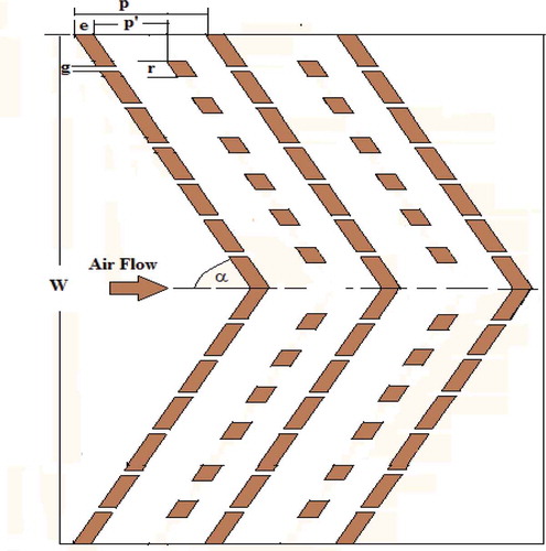
Figure 2. Pictorial view of roughness geometry
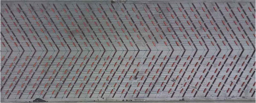
Table 1. Range of parameters of current investigation
2. Experimental setup
2.1. Fabrication of experimental setup
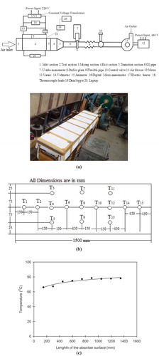
The indoor test facility as per Duffie and Beckman (ASHRAE Standard 93 Citation2003) as shown in ) is fabricated to examine the effect ratio of staggered element size to rib height (r/e) of discrete V-rib integrated with staggered elements on heat transfer and friction factor. A rectangular duct separated in three sections entrance, test and exit. The rectangular duct has a flow cross-section of 200 mm × 25 mm. An electric heater is used for supplying uniform heat flux of 1000 W/m2 to the absorber plate having artificial roughness on its underside. Air extract over the duct by the blower and the flow rate of the air through the duct is controlled by a gate valve. The calibrated orifice plate is connected to U-tube manometer for measurement of flow rate of air. The orifice plate is calibrated with a Pitot tube. After achieving the steady state, the temperature measured at entrance, exit and top of the absorber plate by calibrated copper constantan thermocouples. ) indicates the position of 15 thermocouples fixed on the top of the absorber surface to measure its temperature. The thermocouple wire is fixed to the data logger, and data logger is connected to the computer to show the temperature readings. The pressure loss of the test section is measured with the help of digital micro-manometer (least count of 0.1 Pa).
Figure 3. (a) Sketch and actual photo of test setup (b) Position of thermocouples over absorber surface (c) Variation of absorber surface temperature
2.2. Data reduction
The similar procedure has been used by Ravi and Saini (Citation2018), Kumar, Prajapati and Samir (Citation2017) to calculate the following key parameters.
The average temperature of air Tf is determined by the average of air inlet and outlet temperature. The inlet temperature of air recorded one thermocouple and outlet temperature of air noted five thermocouples fixed in span wise.
The absorber surface average temperature Tp is determined by the average of the temperature of 15 thermocouples at different locations on the top of absorber surface.
The pressure loss (∆P)o across the orifice plate is used to determine the mass flow rate of air (m).
The velocity of air is determined from EquationEquation (5)(5)
(5) :
The Re for flow of air in the duct is determined from EquationEquation (6)(6)
(6) :
The pressure loss in test section (∆P)d is used to determine the friction factor (f):
Dh is defined as:
Useful heat gain is the heat transfer to the air from the heated absorber surface and is obtained from the known values of air inlet and outlet temperatures Ti and To, respectively.
Heat loss is determined as Gupta and Kaushik (Citation2009b).
The average heat transfer coefficient is determined from EquationEquation (10)(10)
(10) :
where Ap is the area of the absorber plate (Ap = Width of the roughened plate × Length of the roughened plate)
The heat transfer coefficient is used to calculate the Nu:
Stanton number (St) is defined as:
ηth is defined as:
Uncertainty analysis has been done as per method of Kline and McClintock (Kline and McClintock Citation1953) and uncertainty range in Re, Nu and f is 1.79–4.38%, 3.29–4.60% and 3.63–9.59%, respectively.
3. Results and discussions
3.1. Set-up validation
The experimental values of Nu and f for smooth surface are compared with the values of Nu and f are obtained from the correlations of Modified Dittus-Boelter (Sadik, Shah, and Aung Citation1987) and Modified Blasius (Bhatti and Shah, Citation1987) as indicates in .
Figure 4. Variation of experimental and theoretical value of Nu
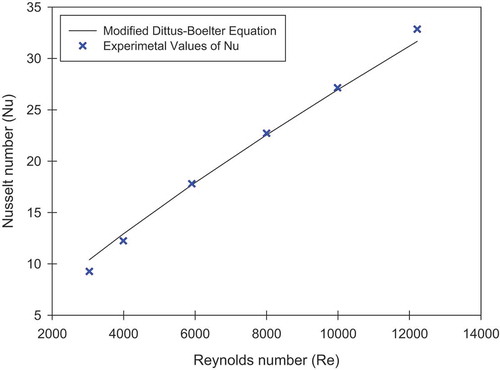
Figure 5. Variation of experimental and theoretical value of f
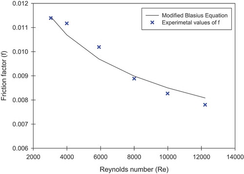
For rectangular duct, 2Rav/De = (1.156 +H/W – 1)/(H/W)
Maximum deviation of experimental and theoretical value of Nu and f is obtained 7.13% and 5.11%, respectively.
3.2. Flow field near the rib roughness wall
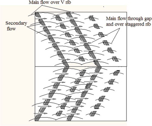
It is considered that augmentation in Nu and f in the rib roughened duct are because changes in the flow field near the rib roughened wall. Many investigators in the earlier (Momin, Saini, and Solanki Citation2002; Karwa Citation2003; Singh, Chander, and Saini Citation2011; Patil, Saini, and Kumar Citation2012; Gill et al. Citation2017) have reported the effect of V-rib on Nu augmentation because the travel of divided secondary flow along the two elements of V-rib. The provision of a gap in an element of V-rib passes the secondary flow by that enhances the velocity of flow down-stream of the gap. The higher velocity jets passed through the gaps boost turbulence between the successive ribs. This helps to enhance the local heat transfer coefficient in relatively low heat transfer region. The staggered element in front of gap divides the flow in top and two sides of it. V-rib with gap and staggered element generate more turbulence as compared to V-rib with gap because scattering of the main flow from the staggered element. As the staggered element placed in the path of secondary flow jets passed from the gaps, the staggered element may be preferably placed in the region where it divides the flow passed through the gaps after extracting a maximal amount of heat and permitting the reattachment of flow near the next gap. shows the flow pattern of the fluid over the roughened surface.
Figure 6. Flow pattern for discrete V-rib integrated with staggered elements
3.3. Variation of Stanton number ratio (Str/Sts) and friction factor ratio (fr/fs) with Reynolds number (Re)
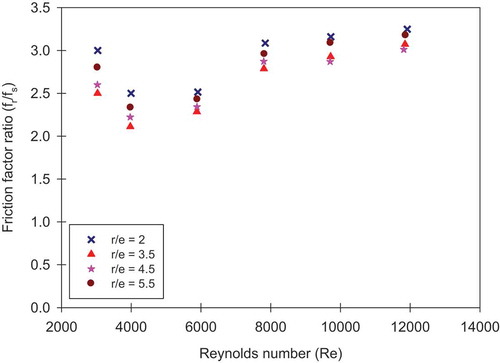
indicate Stanton number ratio (Str/Sts) and friction factor ratio (fr/fs) for different ratios of staggered element size to rib height (r/e) against Re. For the ratio of staggered element size to rib height (r/e) of 3.5, Stanton number ratio (Str/Sts) is 1.58–1.90 over the range of Re investigated. Similarly, for the ratio of staggered element size to rib height (r/e) of 2, 4.5 and 5.5, Stanton number ratio (Str/Sts) is 1.34–1.67, 1.50–1.80 and 1.42–1.69, respectively, over the range of Re investigated. The maximum augmentation of Stanton number is found to be 1.90 times that of the smooth surface for the ratio of staggered element size to rib height (r/e) of 3.5 at Re of 7803. For the ratio of staggered element size to rib height (r/e) of 3.5, friction factor ratio (fr/fs) is 2.11–3.07 over the range of Re investigated. Similarly, for the ratio of staggered element size to rib height (r/e) of 2, 4.5 and 5.5, friction factor ratio (fr/fs) is 2.5–3.24, 2.22–3.01 and 2.33–3.08, respectively, the range of Re investigated. Maximum value of friction factor is obtained 3.24 times that of the smooth surface for the ratio of staggered element size to rib height (r/e) of 2 at Re of 11,916.
Figure 7. Stanton number ratio vs Re
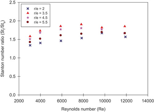
Figure 8. Friction factor ratio vs Re
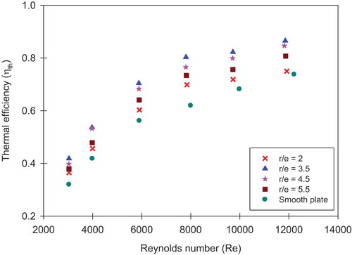
3.4. Variation of thermal efficiency (ηth) against Reynolds number (Re)
indicates the variation of thermal efficiency (ηth) for different ratio of staggered element size to rib height (r/e) against Reynolds number (Re) and temperature rise parameters (∆T/I). From the figures, it indicate the ηth of SAH duct with roughened and smooth surface increases with increasing Re. It is due to the ηth is a function of useful heat gain (Qu) and as the Re increases the rate of heat transfer increases, therefore the ηth increasing. The result indicates that the SAH duct with roughened surface having ratio of staggered element size to rib height (r/e) of 3.5 gives maximum ηth as compared to roughened surface having r/e of 2, 4.5 and 5.5, and also smooth surface entire range of Re.
Figure 9. Thermal efficiency (ηth) vs Re
4. Correlation for Nusselt number (Nu) and friction factor (f)
Data obtained from the experiment are used to development of statistical correlation on the basis of regression analysis. plotted Nu against Re for all data are obtained from the experiment. The power-law equation between Nu and Re is given below
Figure 10. Plot of Nu vs Re
where constant Ao is a function r/e. The value of (Nu/Re0.9248 = Ao) is plotted in as a function of r/e. Finally empirical correlation for Nu:
Figure 11. Plot of Nu/Re0.9248 vs r/e
An identical method has been adopted for correlation development of friction factor (f).
plotted f against Re for all data are obtained from the experiment. The power-law equation between f and Re is given below:
Figure 12. Plot of f vs Re
where constant Bo is a function r/e. The value of (f/Re−0.2355 = Bo) is plotted in as a function of r/e. Finally, empirical correlation for f:
Figure 13. Plot of f/Re−0.2355 vs r/e
Comparison of experimental and predicted values of Nu and f plotted in . From the figures, it is observed that the deviations are ±14% and ±11% for Nu and f, respectively.
Figure 14. Plot of Nupredicted vs Nuexperimental.
Figure 15. Plot of fpredicted vs fexperimental.
5. Conclusion
The current experimental analysis has been done to augmentation the thermal performance of SAH duct with roughened surface. The following conclusions are based on above results:
Discrete V-rib integrated with staggered elements considerably augments the heat transfer over the smooth surface. The augmentation in Stanton number lies in the range of 1.34–1.90 for a range of Re investigated.
The maximum augmentation in Stanton number is obtained corresponding to the ratio of staggered element size to rib height (r/e) of 3.5.
The maximum increase in friction factor lies in the range of 2.11–3.24 for a rage of Re studied. In addition, ratio of staggered element size to rib height (r/e) of 2 gives maximum friction loss as compared to r/e of 3.5, 4.5 and 5.5.
Empirical correlation for Nu and f has been developed.
Disclosure Statement
No potential conflict of interest was reported by the authors.
Additional information
Notes on contributors
Sumer Singh Patel
Sumer Singh Patel is a Ph.D. research scholar in the Department of Mechanical Engineering of Maulana Azad National Institute of Technology Bhopal.
Atul Lanjewar
Dr. Atul Lanjewar working as Associate Professor in the Department of Mechanical Engineering of Maulana Azad National Institute of Technology Bhopal.
References
- Aharwal, K. R., B. K. Gandhi, and J. S. Saini. 2009. “Heat Transfer and Friction Characteristics of Solar Air Heater Ducts Having Integral Inclined Discrete Ribs on Absorber Plate.” International Journal of Heat and Mass Transfer 52 (25–26): 5970–5977. doi:10.1016/j.ijheatmasstransfer.2009.05.032.
- ASHRAE Standard 93. 2003. Method of Testing to Determine the Thermal Performance of Solar Collectors. Atlanta, GA: American Society of Heating, Refrigeration and Air Conditioning Engineers.
- Bharadwaj, G., Varun, R. Kumar, and A. Sharma. 2017. “Heat Transfer Augmentation and Flow Characteristics in Ribbed Triangular Duct Solar Air Heater: An Experimental Analysis.” International Journal of Green Energy 14 (7): 587–598. doi:10.1080/15435075.2017.1307751.
- Bhatti, M. S., and R. K. Shah. 1987. Turbulent and Transition Flow Convective Heat Transfer in Ducts. New York: John Willey & Sons.
- Chaube, A., P. K. Sahoo, and S. C. Solanki. 2006. “Analysis of Heat Transfer Augmentation and Flow Characteristics Due to Rib Roughness over Absorber Plate of a Solar Air Heater.” Renewable Energy 31 (3): 317–331. doi:10.1016/j.renene.2005.01.012.
- Deo, N. S., S. Chander, and J. S. Saini. 2016. “Performance Analysis of Solar Air Heater Duct Roughened with Multigap V-down Ribs Combined with Staggered Ribs.” Renewable Energy 91: 484–500. doi:10.1016/j.renene.2016.01.067.
- Gill, R. S., V. S. Hans, J. S. Saini, and S. Singh. 2017. “Investigation on Performance Enhancement Due to Staggered Piece in a Broken Arc Rib Roughened Solar Air Heater Duct.” Renewable Energy 104: 148–162. doi:10.1016/j.renene.2016.12.002.
- Gill, R. S., V. S. Hans, and S. Singh. 2017. “Investigations on Thermo-hydraulic Performance of Broken Arc Rib in a Rectangular Duct of Solar Air Heater.” International Communications in Heat and Mass Transfer 88: 20–27. doi:10.1016/j.icheatmasstransfer.2017.07.024.
- Gupta, D., S. C. Solanki, and J. S. Saini. 1993. “Heat and Fluid Flow in Rectangular Solar Air Heater Ducts Having Transverse Rib Roughness on Absorber Plates.” Solar Energy 51 (1): 31–37. doi:10.1016/0038-092X(93)90039-Q.
- Gupta, D., S. C. Solanki, and J. S. Saini. 1997. “Thermohydraulic Performance of Solar Air Heaters with Roughened Absorber Plates.” Solar Energy 61 (1): 33–42. doi:10.1016/S0038-092X(97)00005-4.
- Gupta, M. K., and S. C. Kaushik. 2009a. “Performance Evaluation of Solar Air Heater for Various Artificial Roughness Geometries Based on Energy, Effective and Exergy Efficiencies.” Renewable Energy 34 (3): 465–476. doi:10.1016/j.renene.2008.06.001.
- Gupta, M. K., and S. C. Kaushik. 2009b. “Performance Evaluation of Solar Air Heater for Various Artificial Roughness Geometries Based on Energy, Effective and Exergy Efficiencies.” Renewable Energy 34 (3): 465–476. March 1. doi:10.1016/j.renene.2008.06.001.
- Hans, V. S., R. P. Saini, and J. S. Saini. 2010. “Heat Transfer and Friction Factor Correlations for a Solar Air Heater Duct Roughened Artificially with Multiple V-ribs.” Solar Energy 84 (6): 898–911. doi:10.1016/j.solener.2010.02.004.
- Karwa, R. 2003. “Experimental Studies of Augmented Heat Transfer and Friction in Asymmetrically Heated Rectangular Ducts with Ribs on the Heated Wall in Transverse, Inclined, V-continuous and V-discrete Pattern.” International Communications in Heat and Mass Transfer 30 (2): 241–250. doi:10.1016/S0735-1933(03)00035-6.
- Kline, S. J., and F. A. McClintock. 1953. “Describing Uncertainties in Single Sample Experiments.” Mechanical Engineering 75: 3–8.
- Kumar, A., R. P. Saini, and J. S. Saini. 2012. “Heat and Fluid Flow Characteristics of Roughened Solar Air Heater ducts–A Review.” Renewable Energy 47: 77–94. doi:10.1016/j.renene.2012.04.001.
- Kumar, A., R. P. Saini, and J. S. Saini. 2013. “Development of Correlations for Nusselt Number and Friction Factor for Solar Air Heater with Roughened Duct Having Multi V-shaped with Gap Rib as Artificial Roughness.” Renewable Energy 58: 151–163. doi:10.1016/j.renene.2013.03.013.
- Kumar, K., D. R. Prajapati, and S. Samir. 2017. “Heat Transfer and Friction Factor Correlations Development for Solar Air Heater Duct Artificially Roughened with ‘S’shape Ribs.” Experimental Thermal and Fluid Science 1 (82): 249–261. April. doi:10.1016/j.expthermflusci.2016.11.012.
- Lanjewar, A., J. L. Bhagoria, and R. M. Sarviya. 2011. “Heat Transfer and Friction in Solar Air Heater Duct with W-shaped Rib Roughness on Absorber Plate.” Energy 36 (7): 4531–4541. doi:10.1016/j.energy.2011.03.054.
- Maithani, R., and J. S. Saini 2016. “Heat Transfer and Friction Factor Correlations for a Solar Air Heater Duct Roughened Artificially with V-ribs with Symmetrical Gaps.” Experimental Thermal and Fluid Science 70: 220–227. doi:10.1016/j.expthermflusci.2015.09.010.
- Maithani, R., and J. S. Saini. 2017a. “Heat Transfer and Fluid Flow Behaviour of a Rectangular Duct Roughened with V-ribs with Symmetrical Gaps.” International Journal of Ambient Energy 38 (4): 347–355. May 19. doi:10.1080/01430750.2015.1100681.
- Maithani, R., and J. S. Saini. 2017b. “Performance Evaluation of Solar Air Heater Having V-ribs with Symmetrical Gaps in a Rectangular Duct of Solar Air Heater.” International Journal of Ambient Energy 38 (4): 400–410. May 19. doi:10.1080/01430750.2015.1133455.
- Momin, A. M. E., J. S. Saini, and S. C. Solanki. 2002. “Heat Transfer and Friction in Solar Air Heater Duct with V-shaped Rib Roughness on Absorber Plate.” International Journal of Heat and Mass Transfer 45 (16): 3383–3396. doi:10.1016/S0017-9310(02)00046-7.
- Pandey, N. K., and V. K. Bajpai. 2016. “Experimental Investigation of Heat Transfer Augmentation Using Multiple Arcs with Gap on Absorber Plate of Solar Air Heater.” Solar Energy 134: 314–326. doi:10.1016/j.solener.2016.05.007.
- Patel, S. S., and A. Lanjewar. 2018. “Experimental Analysis for Augmentation of Heat Transfer in Multiple Discrete V-patterns Combined with Staggered Ribs Solar Air Heater.” Renewable Energy Focus 1 (25): 31–39. June. doi:10.1016/j.ref.2018.03.003.
- Patil, A. K., J. S. Saini, and K. Kumar. 2012. “Heat Transfer and Friction Characteristics of Solar Air Heater Duct Roughened by Broken V-shape Ribs Combined with Staggered Rib Piece.” Journal of Renewable and Sustainable Energy 4 (1): 013115. doi:10.1063/1.3682072.
- Prasad, B. N., and J. S. Saini. 1988. “Effect of Artificial Roughness on Heat Transfer and Friction Factor in a Solar Air Heater.” Solar Energy 41 (6): 555–560. doi:10.1016/0038-092X(88)90058-8.
- Prasad, K., and S. C. Mullick. 1983. “Heat Transfer Characteristics of a Solar Air Heater Used for Drying Purposes.” Applied Energy 13 (2): 83–93. doi:10.1016/0306-2619(83)90001-6.
- Ravi, R. K., and R. P. Saini. 2018. “Nusselt Number and Friction Factor Correlations for Forced Convective Type Counter Flow Solar Air Heater Having Discrete Multi V Shaped and Staggered Rib Roughness on Both Sides of the Absorber Plate.” Applied Thermal Engineering 25 (129): 735–746. January. doi:10.1016/j.applthermaleng.2017.10.080.
- Sadik, K., R. K. Shah, and W. Aung. 1987. Handbook of Single Phase Convective Heat Transfer. New York: Wiley.
- Sahu, M. M., and J. L. Bhagoria. 2005. “Augmentation of Heat Transfer Coefficient by Using 90 Broken Transverse Ribs on Absorber Plate of Solar Air Heater.” Renewable Energy 30 (13): 2057–2073. doi:10.1016/j.renene.2004.10.016.
- Saini, S. K., and R. P. Saini. 2008. “Development of Correlations for Nusselt Number and Friction Factor for Solar Air Heater with Roughened Duct Having Arc-shaped Wire as Artificial Roughness.” Solar Energy 82 (12): 1118–1130. doi:10.1016/j.solener.2008.05.010.
- Sharma, A., G. Bharadwaj, and Varun. 2017. “Heat Transfer and Friction Factor Correlation Development for Double-pass Solar Air Heater Having V-shaped Ribs as Roughness Elements.” Experimental Heat Transfer 30 (1): 77–90. doi:10.1080/08916152.2016.1161676.
- Singh, A. P., and S. Varun. 2014. “Heat Transfer and Friction Factor Correlations for Multiple Arc Shape Roughness Elements on the Absorber Plate Used in Solar Air Heaters.” Experimental Thermal and Fluid Science 54: 117–126. doi:10.1016/j.expthermflusci.2014.02.004.
- Singh, S., S. Chander, and J. S. Saini. 2011. “Heat Transfer and Friction Factor Correlations of Solar Air Heater Ducts Artificially Roughened with Discrete V-down Ribs.” Energy 36 (8): 5053–5064. doi:10.1016/j.energy.2011.05.052.
- Singh, S., B. Singh, V. S. Hans, and R. S. Gill. 2015. “CFD (Computational Fluid Dynamics) Investigation on Nusselt Number and Friction Factor of Solar Air Heater Duct Roughened with Non-uniform Cross-section Transverse Rib.” Energy 84: 509–517. doi:10.1016/j.energy.2015.03.015.
- Varun, A. Patnaik, R. P. Saini, and S. K. Singal. 2009. “Performance Prediction of Solar Air Heater Having Roughened Duct Provided with Transverse and Inclined Ribs as Artificial Roughness.” Renewable Energy 34 (12): 2914–2922. doi:10.1016/j.renene.2009.04.030.
- Verma, S. K., and B. N. Prasad. 2000. “Investigation for the Optimal Thermohydraulic Performance of Artificially Roughened Solar Air Heaters.” Renewable Energy 20 (1): 19–36. doi:10.1016/S0960-1481(99)00081-6.