
ABSTRACT
Globally, energy crisis focusses on the researchers to explore innovative and alternative sources of energy. This tribulation has acute for the developing countries. Generation of any kind of waste is a vital problem for the environment. Some wastes have the characteristics of producing energy by different thermochemical conversions. Inaugurate of using plastics has curtailed many problems in our daily life. Waste plastics are assessed as harmful things when it is thrown into the landfill because of their non-degradable property. Plastic waste is becoming a tremendous threat to the environment as a little fraction of it is being recycled through plastic re-production. Rest of them are thrown into the landfill or incinerated. To get rid of the environmental problem and to recover fuel, municipal waste plastics were converted into a liquid hydrocarbon by using catalyst at a temperature range of 250–400°C. Aluminium oxide (Al2O3) and zinc oxide (ZnO) were used as a catalyst in this study. The maximum conversion was found 78 ± 2% when the catalyst percentage was 5%. Fuel quality was tested using ASTM standard method and compared with other commercial-grade gasoline and diesel oil. The density and kinematic viscosity of the oil were found as 779 kg/m3 and 2.693 cSt. Research Octane number (RON) of produced oil was 84. Physical properties such that flash points, pour point and cetane index of produced oil were also measured and found as 20°C, less than 3 and 65.5, respectively. The properties of produced oil were much closer to that of diesel oil. It could be concluded that plastic waste may be a potential source of alternative fuels.
1. Introduction
The future existence of human civilisation is threatened due to the depletion of non-renewable natural resources. To protect the natural environment and to mitigate climate change, consumption of natural resources must be reduced. Therefore, researchers are working to find out alternate ways that have lower impact on the environment. They also focus on the utilisation of renewable energy sources and different types of waste (Stelmachowski and Słowiński Citation2012). In recent years, the quantity of solid wastes has increased significantly in both industrialised and developing countries, raising the question of the sustainability of waste disposal management (Kwak et al. Citation2006). The European commission (EU) has proposed that around half of the 10% biofuels goal should be met by second-generation biofuels produced from non-feedstock, such as waste and straw. Among these, 10% share of energy used in the transport sector is targeted to be renewable by 2020. In addition, the Fuel Quality Directive set a target of a 6% greenhouse gas reduction for fuels used in the transport sector by 2020 (Psomopoulos et al. Citation2014). According to World Bank, almost 8–12% of total municipal wastes generated from plastic wastes (PW), and it is estimated that its generation will go up to 9–13% of total municipal wastes in 2025 (Hoornweg and Bhada-Tata Citation2012). Low-density polyethylene (LDPE), High-density polyethylene (HDPE), Polypropylene (PP), and Polystyrene (PS) are the major components of the total plastic content of municipal solid waste (Kaminsky, Schmidt, and Simon Citation2000; Mastral et al. Citation2002; Onu et al. Citation1999; Williams and Williams Citation1999). It consists of a mixture of different kinds of plastics: 40.5 wt. % HDPE and LDPE, 19.6 wt. % PP, 11.9 wt. % PS, 10.7 wt. % PVC (Polyvinyl chloride), 8.1 wt. % PET (Poly ethylene terephthalate) and the rest are other polymers (Aguado and Serrano Citation1999).
Adequate treatment of these wastes can extirpate environmental problems and make possible a sustained development of modern society. Plastics have a high heating value (i.e. Polyethylene 43 MJ/kg, polypropylene 44 MJ/kg, polyvinyl chloride 20 MJ/kg) and combustion of plastics can be used to recover it (Arandes et al. Citation1997). However, the combustion products of plastics have a bad impact on the human body. Burning plastics containing organo-chlor-based substances (e.g. PVC) can cause the most dangerous emissions. Toxic chemicals, e.g. Dioxin, emit when such plastics are burned. Dioxins are a group of chemically related compounds that are persistent environmental pollutants (POPs). The chemical name for dioxin is 2, 3, 7, 8-tetrachlorodibenzopara dioxin (TCDD). The name ‘dioxins’ is often used for the family of structurally and chemically related polychlorinated dibenzo-para-dioxins (PCDDs) and polychlorinated dibenzofurans (PCDFs). Certain dioxin-like polychlorinated biphenyls (PCBs) with similar toxicity properties are also included under the term ‘dioxins’. Some 419 types of dioxin-related compounds have been identified but only about 30 of these are considered to have significant toxicity, with TCDD is the most toxic. They are carcinogenic and a hormone disruptor and persistent, and they accumulate in our body-fat and initiate various kinds of difficulties. Hence, combustion of plastics cannot be a satisfactory solution to minimise the environmental impact. On the other hand, recycling of plastic waste demands the economic feasibility but the products cannot perform its legacy as its previous condition. Among the plastic recycling processes, carbon recycling by thermal or catalytic cracking is the better alternative approach towards the energy crisis since energy and fuel can be regained by this process which in turn reduces the consumption of natural resources (Wong et al. Citation2015) (Brandrup, Bittner, and Michaeli Citation1996). Pyrolysis process is one of the best approaches to preserve petroleum resources (Al-Salem, Lettieri, and Baeyens Citation2009; Bajus and Hájeková Citation2010). It is a thermal cracking reaction of the large molecular weight polymer carbon chains that produce small molecular weight molecules under oxygen-free environment (Regnier and Mortaigne Citation1995). It gained importance over other recycling processes as it reduces the carbon footprint of plastic products. At the same time, the emissions of toxic gases, such as carbon monoxide and carbon dioxide are minimised (Al-Salem et al. Citation2017). Pyrolysis, one of the energy recovery methods, can be done by both thermal and catalytic processes. Generally, because of the reduction of the cracking temperature, narrow product distribution and control of the selectivity, catalytic process has been preferred over thermal process (Achilias et al. Citation2007; Auxilio et al. Citation2017; Panda and Singh Citation2013). Moreover, as the thermal cracking process is wholly dependent on temperature, there are some limitations in the conventional thermal pyrolysis (Sadef et al. Citation2016). The effect of reaction time at the variable temperature on the superiority of plastic pyrolysis products and their physical possessions can be a useful understanding of the applicability of such a process in a more economical way. Properties of liquid products and gas composition were investigated and it has been highly predicted that the results obtained will ascend the understanding of the applicability and limitation of these waste materials as a feedstock for the production of alternative liquid fuel (Das and Tiwari Citation2018). The liquid oil produced by thermal pyrolysis is of low quality, and it contains impurities like residues, chlorine, etc. (Borsodi et al. Citation2011). To resolve these problems, catalytic pyrolysis of plastics has emerged where different types of catalysts are used. Researchers have already utilised different catalysts, such as Red mud, Fe2O3 (Sarker and Rashid Citation2013), Al2O3, Ca(OH)2 (Syamsiro et al. Citation2014), ZSM-5 (López et al. Citation2011), FCC (Lee Citation2009), HZSM-5 (Del Remedio Hernandez et al. Citation2007), Y-Zeolite (Lee Citation2012), natural zeolite (Wang and Wang Citation2011), silica-alumina (Luo et al. Citation2000), activated carbon (Kumar et al. Citation2017), and they are still searching for effective low-cost catalysts to improve the liquid fuel quality as well as liquid yield. In addition, some other parameters have a great influence on the quality and yield of the liquid product, such as waste plastic types and composition, reactor type, temperature, residence time, catalyst and heating rate. Biofuels offer the aptitude of numerous benefit correlated to energy refuge, economics, and the environment. The advantage realised by the use of renewable sources for the production of biofuels is the operation of expected bioresources (more geographically spread than fossil fuels) and erection of bio-energy which provides the individuality and security of energy supply (Psomopoulos et al. Citation2014). In this study, the main objective was to recover liquid fuel from the mixture of waste plastic (LDPE, HDPE, PP and PS) by using an individual catalyst and a mixture of catalysts at a temperature range of 250–400°C. The physical and chemical properties of the produced fuel were also characterised and compared with conventional fuel.
2. Experimental setup
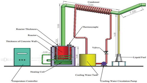
Waste Plastic (LDPE, HDPE, PP, PS) was collected from the local municipality, Sylhet. After washing the plastic with NaOH solution to remove impurities, it was dried, shredded and cut into small pieces. A mixture of 250 ± 0.8 g of weighed plastic and 1–7% catalyst (aluminium oxide and zinc oxide) was fed to the properly sealed reactor to protect the gas from leaking. Three catalyst beds were supported by stainless-steel structured plate inside of the reactor and deployed over the melting waste plastics. The beds of catalysts were used to crack the hydrocarbon chain in vapourthe phase. Experiment setup required accessories and equipment such as the stainless-steel reactor. Copper tube was used here as a condenser for cooling water circulation. The length of the tube from the reactor is 32 inches long. The vapour of the fuel producing from the reactor goes through the tube and reaches to the condenser section. While travelling this path, the fuel vapour losses its reaction enthalpy and becomes cooler than reaction or cracking temperature. The condenser section is only used for cooling purposes. From the schematic diagram, it is clear that the fuel vapour can never be in direct contact with the copper tube. Therefore, it has no effect on the catalytic reaction. The main constituents of the experimental set-up were the U-shaped stainless-steel tube, electrical heater to maintain the inside temperature of the reactor, fixed-bed reactor chamber, copper tube for cooling water system, the liquid collecting bottle, the gravity-fed reactor feeder, thermocouples with temperature display, weight balance, measuring cylinder, filter paper, and a centrifugal pump. The heater was controlled by separate switches. The reactor surface was thermally insulated with the thick concrete wall. All equipment’s and accessories were connected properly according to the required basis. The schematic diagram of the experimental setup constructed for the study is shown in .
Figure 1. Schematic diagram of the experimental setup
3. Process description
Conversion of waste plastic into liquid fuel was performed in a batch reactor without a vacuum system. Raw material composition and types are shown in . Plastic bags like polythene bags, packaging polymer, wrapping plastics were selected as a feed of first type sample tagged as Sample A. Basically, these products are processed from LLDPE, Low-density polyethylene (LDPE), polypropylene (PP) and polystyrene (PS). The second type was collected from the broken jug, rejected plastic containers, broken plastic soap cases, broken plastic toys and other various waste plastic pyrolysis from the reactor tagged as Sample B. These types of products are produced from High-density polyethylene (HDPE) and Polypropylene (PP).
Table 1. Types and composition of raw plastics
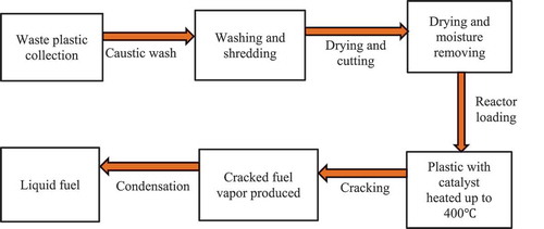
The experimental process is shown in . After the collection of waste plastics, it was washed to remove the impurities, and then it was dried to remove any water droplets. After that, the washed plastic was sorted according to their categories. It has no value when it is thrown into the landfill. Besides, plastic has a very bad impact on the soil because of its non-degradable property. After the collection of raw plastic wastes, it needed to go through several physical processing methods like washing, drying and shredding into pieces. Only washing by caustic soda can be a hazard for the environment. But low concentration caustic soda solution was used in washing the waste plastics. If it is in a large scale, then a water treatment plant can solve this problem easily. Finally, it was shredded and cut into pieces for ease of feeding the raw materials and for good heat transfer. The reactor was properly sealed to protect the gas from leaking. For experimental purposes, 250 ± 0.8 g of waste plastic (LDPE, HDPE, PP and PS) and 1–7% of catalyst were used. A thin layer of catalysts on the bed were used to fill each tray. Each tray was filled with 70 g of catalysts. The weight of catalysts on each tray was measured according to how much catalysts were needed to cover the surface area of the tray.
Figure 2. Experimental procedure of plastic conversion
Prior to the start of the experiment, adequate precautions were taken to make sure that there was no leakage. Then, the heater was started and the reaction continued until the last drop of oil was noticed in the measuring cylinder. The solid waste plastic was first melted and then cracked in the same reactor (converted to smaller units or gases) at different temperatures. Finally, the gas was allowed to pass through the tube. The condenser (folding copper wire) condensed the gas and vapour passing through the tube. As the hot gas and cool water were in indirect contact, there will definitely be an exchange of heat between the gas and cool water. When the first distillate was observed in the measuring cylinder, the temperature and time were recorded. The volume of fuel oil produced was monitored with time and temperature. The procedure was repeated for the aluminium oxide (Al2O3) and zinc oxide (ZnO) catalyst separately and then followed for the mixture of both catalysts. First, the catalysts were used with waste plastics feed, and after this method, we applied the second method where the catalyst beds also used along with the first method. In this experiment, aluminium oxide and zinc oxide ratio was 2:1. The reaction duration was 40 to 50 minutes for catalysts used with the feed. For catalysts and catalyst beds, both the reaction duration was 60 to 70 minutes but the conversion was better than the previous method. A better result was observed in the mixture of zinc oxide (ZnO) and aluminium oxide (Al2O3) catalyst when the percentage was 5% and catalyst beds were used at the time. A systematic error was corrected for the experiment using statistical tools, e.g. Standard deviation of the mean.
4. Results and discussion
4.1. Chemical properties
The produced fuel samples were analysed for determining fuel characteristics in terms of their properties. According to the ASTM standard, properties of fuel were determined by 13 C and 1 H Nuclear magnetic Resonance (NMR) and Gas Chromatography (GC). The liquid product’s chemical composition mostly consisted of alkanes, alkenes and aromatics which were evenly distributed by carbon number. Report details were analysed and composition types and compositions were detected.
4.1.1. 13 C-NMR and 1 H-NMR data analysis
Nuclear Magnetic Resonance (NMR) spectroscopy has been applied to provide detailed information on the hydrocarbon chemistry of raw petroleum and its various products. NMR continues to be an exceedingly useful tool to study the proton and the carbon chemistry of many petroleum-derived products and raw materials. Now it is emphasised to create alternative sources of fuel like coal to liquids, gas to liquids, biofuel, biomass conversion, as well as waste plastics to liquid fuel conversion. The synthetic fuel products produced from these processes should be focused on research and analysis. NMR offers a unique perspective on the chemistry of these products. NMR experiments relate to molecular mobility, viscosity and paramagnetic nuclear interactions. H-NMR and C-NMR techniques known as Distortion less Enhancement by Polarisation Transfer (DEPT) allow the discernment between methyl (CH3), methylene (CH2), methane (CH) and quaternary carbon. To analyse hydrogen branching, crucial data calculation of atomic ring system sizes and average molecular description NMR is the best technique.
The fuel samples had been analysed for determining the functional group by C-NMR or H-NMR test from Bangladesh Council of Scientific and Industrial Research (BCSIR), Dhaka, Bangladesh. The test reports also included here in . Samples were collected from different types of waste plastics which were available as garbage. Sample A and Sample B were analysed individually. 1 H-NMR and 13 C-NMR data provide information about the relative amount of the structural composition of the sample. In conjunction with elemental analysis and average molecular weight data, it is possible to obtain qualitative information about the presence of different types of protons and carbons (Burger et al. Citation2015).
According to the 13 C-NMR spectrum, the chemical shift reports were analysed and functional groups were grouped for sample A and sample B individual in and . The carbon NMR reports are also included in .
Figure 3. 13 C-NMR report of sample A
Table 2. Carbon types of liquid fuel in sample A according to the chemical shift range
Table 3. Carbon types of liquid fuel in Sample B according to the chemical shift range
Sample A and Sample B have shown almost the same carbon type excluded some variations. This information provides functional group types, saturated and unsaturated carbon bond types, benzene cycle types and more other properties. H-NMR and C-NMR spectra were recorded on a BRUKER AVANCE 400 NMR spectrometer which has been operated at 400 MHz for 1 H-NMR and 100 MHz for 13 C-NMR using a C/H duel 5 mm probe. To analyse the sample for 13 C-NMR and 1 H-NMR, CDC13 solvent was used with 11.22 seconds recycle delay and 296.6 K time-domain data. Chemical shifts were reported relative to tetramethylsilane (TMS) used on international standard. All experiments were performed at room temperature.
Figure 4. 13 C-NMR report of sample B
Proton NMR was analysed to detect the proton type from the samples. The proton types were described here according to the chemical shift of 1 H-NMR reports. The report including analysis is shown in and .
Figure 5. 1 H-NMR report of sample A
Figure 6. 1 H-NMR report of sample B
Table 4. Proton types of liquid fuel in sample A according to the chemical shift range
Table 5. Proton types of liquid fuel in sample B according to the chemical shift range
The analysis of complex hydrocarbon compounds in both fuel samples with respect to their types and functional groups was depicted from the NMR spectroscopy. H-NMR and C-NMR spectra in – can be divided into several spectral regions. In , the characteristic functional groups of both samples, the spectral regions in which their carbons and protons resonate and grouped regions of their interests were presented. Integral carbon and proton peak intensities are proportional to the number of carbon and hydrogen nuclei in each functional group. The numerical values of peak allow for the direct determination of their types without any doubt. From the 13 C-NMR, 1 H-NMR spectrum and chemical shift reports, it can be said that the fuel samples belonged to the aromatic, alkane, alkene and alkyne by their properties and characters. From the assertion of the gas chromatography report, it is clear that the content of the sample liquid fuel has sufficient and different carbon chain compounds.
4.1.2. Gas chromatography data analysis
The chemical composition is the most important property of fuel. Gas chromatography (GC) has been conducted in the Institute of National Analytical Research and Service (INARS), Bangladesh Council of Scientific and Industrial Research (BCSIR), Dhaka, Bangladesh, and hereby ensured about the fuel chemical composition. GC chromatogram of the plastic fuel was described in .
Table 6. Chemical compositions obtained from gas chromatography
4.2. Physical properties
For marketing purpose, the fuel should have some physical properties. The physical properties of produced fuel and its comparison with other traditional fuel are given in .
Table 7. Properties of produced fuel and comparison
The test results render the potentiality of produced fuel as an alternative of diesel and gasoline. According to the result, density was found 0.779 kg/L which is within the range of diesel and gasoline. Therefore, the produced fuel will not cause any damage to the engine if it is used as transportation fuel, rather fuel consumption will be less. Kinematic viscosity is another important property of fuel, which has an effect on fuel consumption, engine temperature and the injection system because of resistance of flow at high viscosity. The viscosity of fuel obtained meets the quality of diesel and gasoline (2.6983 centipoise @ 60° F). The flash point is important for greater safety in handling and storage. However, flash point of produced fuel was slightly lower than the diesel; it can be increased after removing the lighter components present in liquid fuel. Cetane number or cetane index represents the auto ignitability of the fuel. Cetane index of the produced oil was higher than that of diesel. Therefore, it has better ignitability, because the higher the cetane index the better the engine performance. Low-temperature installations are determined by pour point. It is the temperature at which paraffin content in the fuel crystallised and become resistant to flow. Pour point of the produced fuel was less than 3°C which determines the least limit of flow and it is of the same quality as diesel. Reid vapour pressure (RVP) is used as a criterion for blending of product and is also used to estimate the losses from storage tanks during filling and draining. It was found as 0.6 psi, which is close to diesel, but less than gasoline RVP. There will be no SOx, NOx or other toxic compound emissions as no sulphur content was found in the fuel. Moreover, ash content was also very low compared to diesel. Carbon residue was only 0.1%, which mean it has a very low tendency to deposit carbonaceous residue on hot surfaces and hence will have less fouling. The gross heating value of the produced fuel was found slightly higher than diesel and gasoline, which indicates that this fuel will produce more power in the engine. The octane number was also found similar to gasoline and diesel grade fuel. Moreover, PONA analysis was used to know the paraffin, naphtha, olefin and aromatic content in the fuel which is shown in .
4.3. Effect of temperature on conversion rate
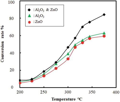
The effect of temperature on the conversion rate for the catalytic cracking of waste plastic is shown in . The conversion rate increased and the reaction time decreased with an increase in temperature. High temperature supports the easy cleavage of bonds, and thus speeds up the reaction and lowers the reaction time. This shows that temperature has a significant effect on reaction time and yield of liquid. Moreover, gaseous or char product is preferred over 500°C, whereas the liquid product is preferred at a lower temperature range 300–500°C (Anene et al. Citation2018; Sharuddin et al. Citation2018). For instance, reaction temperature used for HDPE: 350°C and 450°C, for LDPE: 430°C, and for PP: 300°C (Anene et al. Citation2018) (Ahmad et al. Citation2015). In this experiment, catalytic pyrolysis of plastic was done in the range of 250–400°C. Plastic cracking began at 150 ± 5°C and then it started to provide fuel as liquid droplet after being condensed through the condenser. When catalysts were introduced with feed and catalyst beds were not used the temperature reached 200°C, it completed almost 23% of conversion. Conversion increased with the temperature and no liquid droplet is found after 400°C. Final conversion was found 78 (± 2.5) % at 330 ± 10°C. shows the conversion trend with temperature both for individual and mixed catalyst. In case of using catalysts and catalyst beds both at 200°C only 10–15% conversion was done. When the temperature reached over 300°C then the conversion rate started to go up and final conversion rate reached 83 (±2.5) % till 400°C. describes the conversion trend with temperature for both catalysts and catalyst beds were used together.
Figure 7. Combination of temperature (°C) Vs. conversion rate (%) when catalysts used without catalyst beds
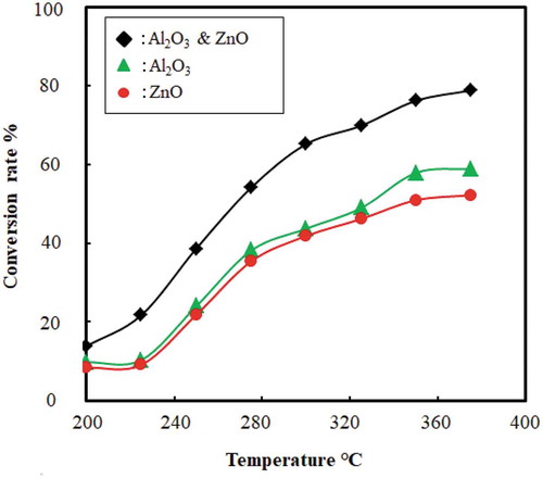
Figure 8. Combination of temperature (°C) Vs. conversion rate (%) when catalysts and catalyst beds both used
4.4. Effect of reaction time on conversion rate
The effect of reaction time on the conversion rate for the catalytic cracking of waste plastic without catalyst beds is shown in .
Figure 9. Combination of conversion rate (%) vs. reaction time (min) when catalysts used without catalyst beds
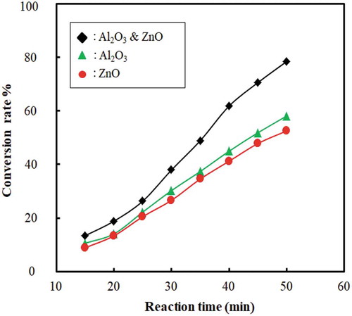
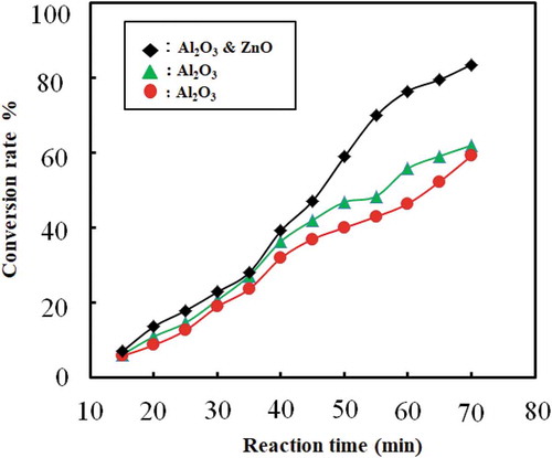
The conversion rate increases with an increase in reaction time. Thus, reaction time plays a vital role in conversion and yield of liquid fuel. After reaching the desired temperature, the process is maintained at the temperature (400–450°C). If the temperature increased more than this temperature, the amount of gas or char product increased instead of liquid product. The set point of the reactor was maintained 400–450°C because the controller controlled the heating rod with 8–10°C offset. Reaction time in this experiment was 40 to 50 min and conversion was found 78 ± 2.5% when catalysts were only used with feed and catalyst beds were not used. The liquid oil yield was 74 ± 2%, whereas solid content was 22% and the rest were gaseous component. When catalysts and catalyst beds both were used then the reaction time increased around 60 to 70 minutes because initially heat was consumed to heat up feed and catalyst beds both. But the conversion rate increased to 83 ± 2.5%. In this case, the liquid oil yield and solid content were around 82% and 11%, respectively, and rest were gaseous product. By this method, gaseous product was more than the previous way. In this way, long-chain polymer first cracked at the liquid phase and then again cracked in the gaseous phase at high temperature inside the reactor when it passed through the catalyst beds. shows the combination of the rate of conversion rate and reaction time when both catalysts and catalyst beds were used. In literature, researchers found 74.5% at 450°C oil yield from HDPE at 60 min (Miskolczi et al. Citation2004), 69.8% oil yield at 300°C from PP at 30 min (Ahmad et al. Citation2015).
Figure 10. Combination of conversion rate (%) vs. reaction time (min) when catalysts and catalyst beds both used
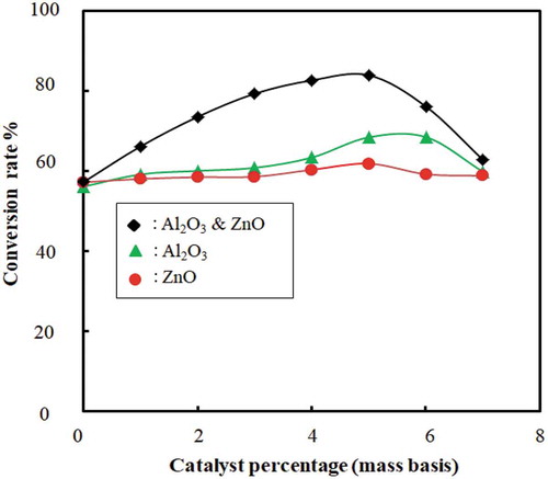
4.5. Effect of catalyst amount on conversion rate
The effect of catalyst amount on the conversion rate with and without catalyst beds for the catalytic cracking of waste plastic is shown in and . The conversion rate is increased and the temperature decreased with an increase in catalyst amount. This indicates that the catalyst amount has a significant effect on better conversion and yield of liquid fuel. The catalyst acts as channels for a breakdown of large compounds to smaller ones because of the internal pore structure. From and , it is evident that mixed catalyst has higher efficiency to convert waste plastic to fuel than using ZnO and Al2O3 separately. However, the optimum catalyst percentage found was 5 ± 0.2%; beyond this, the conversion decreased. Researchers also used other types of catalyst: ZSM-5 (35% liquid yield) (Miskolczi et al. Citation2004), natural zeolite (23.88% liquid yield) (Sriningsih et al. Citation2014).
Figure 11. Effect of catalyst amount on conversion is shown as conversion rate (%) vs. catalyst amount (g) without catalyst beds
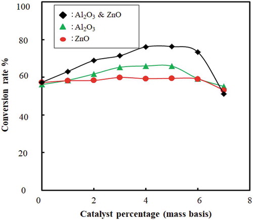
Figure 12. Effect of catalyst amount on conversion is shown as conversion rate (%) vs. catalyst amount (g) with catalyst beds
There is a small amount of char produced after conversion as a by-product of the pyrolysis process. It has the potential to be used in various environmental and energy applications such as heavy metal adsorption from municipal and industrial wastewater and toxic gases (Sharuddin et al. Citation2016). It also has a high heating value and can be used to produce briquette from it. Char can also be used as a feedstock for the activated carbon or source of energy for boilers (Fernández, Arenillas, and Menéndez Citation2011). The produced gaseous product also has a high heating value and can be used for heating or chemical feedstock to produce polyolefin (Fernández, Arenillas, and Menéndez Citation2011; Sharuddin et al. Citation2016). The catalyst was the parameter for completing the reaction comparatively at less temperature than it actually required. Our conversion without catalyst was very low, and the residue was also wax-like compounds. It may be at a high temperature where the conversion would be high, but our reactor was designed for maximum 550° to 600°C. Therefore, we tried our best to provide all data and analysis within this value.
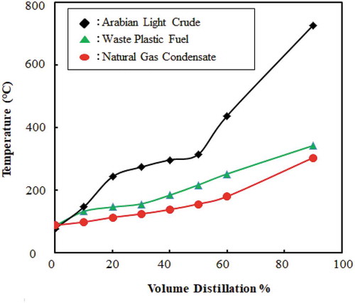
4.6. Distillation properties
The chemical composition of the waste plastic fuel is a mixture of different hydrocarbon of different carbon numbers. To use the fuel by their property, it is needed to fractionate hydrocarbons by distillation. The distillation curve provides a breadth of information about the crude oil or the petroleum fuel. In certain respects, the boiling point distribution is representative of the composition of the petroleum fraction. Therefore, by determining the volume per cent of the components in a conventional hydrocarbon fuel solution, the overall physical properties can be determined. The ASTM Distillation test is done for gasoline, naphtha (A naphtha is a volatile petroleum fraction, usually boiling in the gasoline range), and kerosene (D86). The comparison of the distillation curve among waste plastic fuel, natural gas condensate and Arabian light crude oil is shown in .
Figure 13. Distillation curve comparison waste plastic fuel with Arabian light crude oil and natural gas condensate
4.6.1. Environmental and energy efficiency
Conversion of plastics to fuel requires several physical processing methods like washing, drying and shredding into pieces. Only washing by caustic soda can be hazardous for the environment. However, low concentration caustic soda solution was used in washing the waste plastics in order to reduce the risk to the environment. If it is in a large scale, then a water treatment plant can solve this problem easily, although it increases the cost of pretreatment. Overall, the process has less impact on the environment. Therefore, this process can be an effective way of protecting the environment from non-degradable plastics by converting them into an alternate source of energy.
Pyrolysis process is an endothermic process which requires high energy consumption. Energy is also required during pretreatment, e.g. drying and condensation. In this experiment, total energy consumption was 1.017 kWh, which includes heating (1 kW) for 1 h, drying (0.04 kW) for 15 min, and condensation (0.01 kW) for 45 min. The energy requirement for distillation and other post-treatment steps are not taken into account in this calculation. The energy equivalent of the obtained liquid product is 2.28 kWh considering the heating value of the fuel given in and liquid fuel produced (74%). Moreover, the off-gas generated, although a very small amount, also have some heating value. Hence, it can be concluded that this process is energy efficient. However, a more detailed energy study is required to consider all the pretreatment and post-treatment steps.
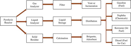
4.6.2. Potential product
Pyrolysis of plastic wastes produced liquid hydrocarbon fuel. However, it cannot be used directly as a transportation fuel since it is composed of various hydrocarbons. The possible way to get the potential product, such as gasoline, naphtha, kerosene, and diesel is shown in . Solid byproduct produced during pyrolysis can also be used as briquette or adsorbent after post-treatment, e.g. calcination. After post-treatment as shown in , the products can be used directly for the desired purpose.
Figure 14. Potential products with specific processes
5. Conclusion
The predicament for waste plastics in Bangladesh and all over the world is now the most undesired condition. After several years around 2050, the amount of waste plastics in the sea will exceed the amount of fishes. Currently, the appropriate management and consumption of waste plastics are being one of the most promising factors for environmental concern. In this experiment, the catalytic thermal process was used to convert a mixture of LDPE, HDPE, PP and PS waste plastic to liquid hydrocarbon fuel. The method is an effective and efficient way to convert vast amounts of waste plastic to a useful source of energy. In this regard, the catalytic pyrolysis studied here presents an efficient, clean and very effective that meaning of removing the refuse that we left behind over the last several decades. The maximum conversion was found 78 ± 2% when the catalyst percentage was 5% and temperature 340 ± 10°C. By converting plastics to fuel, we solve two issues, one is the large plastic seas, and the other is the fuel shortage. This dual benefitwill exist only as long as the waste plastics last, but will surely provide a strong platform for us to build in a sustainable, clean and green future. Catalytic conversion of plastic waste to fuel recovery experiment can be other sources of hydrocarbon like benzene, toluene, etc. by using sophisticate process which needed to more researches and study. Other than traditional fuel, the demand for pure specific hydrocarbon is also appreciated. By using this process, we can utilise waste plastic as a form of alternative source of energy. Overall, the current conversion process is an efficient and sustainable conversion process that can keep the environment clean.
Disclosure statement
No potential conflict of interest was reported by the authors.
Additional information
Notes on contributors
Raihan Ahamed
Mr. Raihan Ahmed is now working in Hyundai Engineering Company limited , Bangladesh.. He completed his B.Sc. in Chemical Engineering and Polymer Science from Shahjalal University of Science and Technology (SUST) Bangladesh.. He was research student at Chemical Engineering and Polymer Science Department. His reseach interest in Energy and Environment His reposibility now on Controlling Gas Dehydration & Distribution Process parameters from DCS and DCS system provided by EMERSON. • Controlling Gas Turbine Compressor by Simatic PCS7 HMI Control system (Turbine Model: Siemens Gas Turbine SGT-400 & SGT-100).
Shameem Hossain
Md. Shameem Hossain is working as an Assistant Professor, Department of Energy Science and Engineerng, Khulna University of Engineering & Technology (KUET). He completed his B.Sc. in Chemical Engineering and Polymer Science from Shahjalal University of Science and Technology (SUST), Bangladesh in 2009. After that, he completed his M. Sc. Eng. in Energy Technology from Khulna University of Engineering & Technology (KUET) in 2015. In the meantime, he has joined as a lecturer in the Department of Energy Science and Engineering (ESE) since 01 Dec, 2014 and later on, he was promoted as an Assistant Professor and has been serving in the same post from Feb 2017 to till date. He has about 10 years of experience in industry, teaching, and research. Before joining as an academician he was working as a shift supervisor in Pertomax Refinery Ltd which is the largest Natural Gas Condensate Refinery Plant on Private sector in Bangladesh. His areas of research are biogas, biofuel, waste management, waste to energy, and alternative fuel. His areas of research interest are clean energy, fuel cell, and sustainable energy.
Mizanul Haque
Md. Mizanul Haque Mizan received his bachelor’s degree (BSc) from Chemical Engineering and Polymer Science Department at Shahjalal University of Science and Technology, Bangladesh in 2017. His research interest was on the sustainable waste management. He was research student in Chemical Engineering and Polymer Science Department. He is currently a second year master student at the University of Twente (Netherlands), studying under the Erasmus Mundus programme. He completed his first year of master’s degree in France and Czech Republic. Currently, he is working with membrane surface science (MSUS) group of the University of Twente; his research focuses on energy and environment and the sustainable polyelectrolyte complex membrane production for nanofiltration applications.
Salma A. Iqbal
Salma A. Iqbal is a Professor and former Head in the Department of Chemical Engineering and Polymer Science, Shahjalal University of Science and Technology, Sylhet, Bangladesh. She was a Visiting Research Scholar,Mary O’Connor Process Safety Center, Texas A & M University, College Station, Texas, USA in 2018.Salma obtained her B.Sc. degree in Chemical Engineering from Bangladesh University of Engineering and Technology (BUET), Dhaka, Bangladesh in 1996, M.Engg. degree from Dublin City University, Dublin, Ireland 2000 and Ph.D degree in Chemical Engineering from Bangladesh University of Engineering and Technology (BUET), Dhaka, Bangladesh in 2012. Dr. Salma is actively involved in research in Chemical Engineering. Her research focuses on the following areas i) Chemical Process Safety ii) Biochemical Engineering iii) Renewable energy iv) Environmental pollution control. She has more than 50 publications. . Her research is supported by IDCOL, World Bank, Ministry of Science and Technology and University Grants Commission, Bangladesh.
References
- Achilias, D., C. Roupakias, P. Megalokonomos, A. Lappas, and Ε. Antonakou. 2007. “Chemical Recycling of Plastic Wastes Made from Polyethylene (LDPE and HDPE) and Polypropylene (PP).” Journal of Hazardous Materials 149 (3): 536–542. doi:10.1016/j.jhazmat.2007.06.076.
- Aguado, J., and D. P. Serrano. 1999. Feedstock Recycling of Plastic Wastes. Royal society of chemistry Vol -1.
- Ahmad, I., M. I. Khan, H. Khan, M. Ishaq, R. Tariq, K. Gul, and W. Ahmad. 2015. “Pyrolysis Study of Polypropylene and Polyethylene into Premium Oil Products.” International Journal of Green Energy 12 (7): 663–671. doi:10.1080/15435075.2014.880146.
- Al-Salem, S., A. Antelava, A. Constantinou, G. Manos, and A. Dutta. 2017. “A Review on Thermal and Catalytic Pyrolysis of Plastic Solid Waste (PSW).” Journal of Environmental Management 197: 177–198. doi:10.1016/j.jenvman.2017.03.084.
- Al-Salem, S., P. Lettieri, and J. Baeyens. 2009. “Recycling and Recovery Routes of Plastic Solid Waste (PSW): A Review.” Waste Management 29 (10): 2625–2643. doi:10.1016/j.wasman.2009.06.004.
- Anene, A., S. Fredriksen, K. Sætre, and L.-A. Tokheim. 2018. “Experimental Study of Thermal and Catalytic Pyrolysis of Plastic Waste Components.” Sustainability 10 (11): 3979. doi:10.3390/su10113979.
- Arandes, J. M., I. Abajo, D. Lopez-Valerio, I. Fernández, M. J. Azkoiti, M. Olazar, and J. Bilbao. 1997. “Transformation of Several Plastic Wastes into Fuels by Catalytic Cracking.” Industrial & Engineering Chemistry Research 36 (11): 4523–4529. doi:10.1021/ie970096e.
- Auxilio, A. R., W.-L. Choo, I. Kohli, S. C. Srivatsa, and S. Bhattacharya. 2017. “An Experimental Study on Thermo-catalytic Pyrolysis of Plastic Waste Using a Continuous Pyrolyser.” Waste Management 67: 143–154. doi:10.1016/j.wasman.2017.05.011.
- Bajus, M., and E. Hájeková. 2010. “Thermal Cracking of the Model Seven Components Mixed Plastics into Oils/waxes.” Petroleum & Coal 52: 3.
- Borsodi, N., N. Miskolczi, A. Angyal, L. Bartha, J. Kohán, and A. Lengyel 2011. “Hydrocarbons Obtained by Pyrolysis of Contaminated Waste Plastics.” Paper presented at the 45th International Petroleum Conference. Bratislava, Slovak Republic.
- Brandrup, J., M. Bittner, and W. Michaeli. 1996. Recycling and Recovery of Plastics. HanserVerlag.Publisher
- Burger, J. L., J. A. Widegren, T. M. Lovestead, and T. J. Bruno. 2015. “1H and 13C NMR Analysis of Gas Turbine Fuels as Applied to the Advanced Distillation Curve Method.” Energy & Fuels 29 (8): 4874–4885.
- Das, P., and P. Tiwari. 2018. “Valorization of Packaging Plastic Waste by Slow Pyrolysis.” Resources, Conservation and Recycling 128: 69–77. doi:10.1016/j.resconrec.2017.09.025.
- Del Remedio Hernandez, M., A. Gómez, Á. N. García, J. Agulló, and A. Marcilla. 2007. “Effect of the Temperature in the Nature and Extension of the Primary and Secondary Reactions in the Thermal and HZSM-5 Catalytic Pyrolysis of HDPE.”.” Applied Catalysis A: General 317 (2): 183–194. doi:10.1016/j.apcata.2006.10.017.
- Fernández, Y., A. Arenillas, and J. Á. Menéndez. 2011. Microwave Heating Applied to Pyrolysis. INTECH Open Access Publisher, Intech 72(2), 723-752
- Hoornweg, D., and P. Bhada-Tata. 2012. What a Waste: A Global Review of Solid Waste Management. Vol. 15. Washington, DC: World Bank.
- Kaminsky, W., H. Schmidt, and C. Simon 2000. “Recycling of Mixed Plastics by Pyrolysis in a Fluidised Bed.” Paper presented at the Macromolecular Symposia.
- Kumar, P. S., M. Bharathikumar, C. Prabhakaran, S. Vijayan, and K. Ramakrishnan. 2017. “Conversion of Waste Plastics into Low-emissive Hydrocarbon Fuels through Catalytic Depolymerization in a New Laboratory Scale Batch Reactor.” International Journal of Energy and Environmental Engineering 8 (2): 167–173. doi:10.1007/s40095-015-0167-z.
- Kwak, T.-H., S. Maken, S. Lee, J.-W. Park, B.-R. Min, and Y. D. Yoo. 2006. “Environmental Aspects of Gasification of Korean Municipal Solid Waste in a Pilot Plant.” Fuel 85 (14–15): 2012–2017. doi:10.1016/j.fuel.2006.03.012.
- Lee, K.-H. 2009. “Thermal and Catalytic Degradation of Pyrolytic Oil from Pyrolysis of Municipal Plastic Wastes.” Journal of Analytical and Applied Pyrolysis” 85 (1–2): 372–379. doi:10.1016/j.jaap.2008.11.032.
- Lee, K.-H. 2012. “Effects of the Types of Zeolites on Catalytic Upgrading of Pyrolysis Wax Oil.”.” Journal of Analytical and Applied Pyrolysis 94: 209–214. doi:10.1016/j.jaap.2011.12.015.
- López, A., I. De Marco, B. Caballero, M. Laresgoiti, A. Adrados, and A. Aranzabal. 2011. “Catalytic Pyrolysis of Plastic Wastes with Two Different Types of Catalysts: ZSM-5 Zeolite and Red Mud.” Applied Catalysis B: Environmental 104 (3–4): 211–219. doi:10.1016/j.apcatb.2011.03.030.
- Luo, G., T. Suto, S. Yasu, and K. Kato. 2000. “Catalytic Degradation of High Density Polyethylene and Polypropylene into Liquid Fuel in a Powder-particle Fluidized Bed.” Polymer Degradation and Stability 70 (1): 97–102. doi:10.1016/S0141-3910(00)00095-1.
- Mastral, F., E. Esperanza, P. Garcıa, and M. Juste. 2002. “Pyrolysis of High-density Polyethylene in a Fluidised Bed Reactor. Influence of the Temperature and Residence Time.” Journal of Analytical and Applied Pyrolysis 63 (1): 1–15. doi:10.1016/S0165-2370(01)00137-1.
- Miskolczi, N., L. Bartha, G. Deák, B. Jover, and D. Kallo. 2004. “Thermal and Thermo-catalytic Degradation of High-density Polyethylene Waste.” Journal of Analytical and Applied Pyrolysis 72 (2): 235–242. doi:10.1016/j.jaap.2004.07.002.
- Onu, P., C. Vasile, S. Ciocılteu, E. Iojoiu, and H. Darie. 1999. “Thermal and Catalytic Decomposition of Polyethylene and Polypropylene.”.” Journal of Analytical and Applied Pyrolysis 49 (1–2): 145–153. doi:10.1016/S0165-2370(98)00109-0.
- Panda, A. K., and R. Singh. 2013. “Experimental Optimization of Process for the Thermo-catalytic Degradation of Waste Polypropylene to Liquid Fuel.” Advances in Energy Engineering (AEE): 1: 3.
- Psomopoulos, C. S., N. Chatziaras, G. C. Ioannidis, and P. Karaisas. 2014. “The Role of the New Commission’s Proposal to Minimize the Climate Impacts of Biofuel Production in Energy and Transport Sectors.”.” Fresenius Environ. Bull 23: 2687–2694.
- Regnier, N., and B. Mortaigne. 1995. “Analysis by Pyrolysis/gas Chromatography/mass Spectrometry of Glass Fibre/vinylester Thermal Degradation Products.” Polymer Degradation and Stability 49 (3): 419–428. doi:10.1016/0141-3910(95)00129-A.
- Sadef, Y., A. Nizami, S. Batool, M. Chaudary, O. Ouda, Z. Asam, A. Demirbas, M. Rehan, and A. Demirbas. 2016. “Waste-to-energy and Recycling Value for Developing Integrated Solid Waste Management Plan in Lahore.” Energy Sources, Part B: Economics, Planning, and Policy 11 (7): 569–579. doi:10.1080/15567249.2015.1052595.
- Sarker, M., and M. M. Rashid. 2013. ““Waste Plastics Mixture of Polystyrene and Polypropylene into Light Grade Fuel Using Fe2O3 Catalyst.” Int. J. Renew.” Energy Technol. Res 2 (1): 17–28.
- Sharuddin, S., F. Abnisa, W. Daud, and M. Aroua 2018 “Pyrolysis of Plastic Waste for Liquid Fuel Production as Prospective Energy Resource.” Paper presented at the IOP Conference Series: Materials Science and Engineering. Indonesia.
- Sharuddin, S. D. A., F. Abnisa, W. M. A. W. Daud, and M. K. Aroua. 2016. “A Review on Pyrolysis of Plastic Wastes.” Energy Conversion and Management 115: 308–326. doi:10.1016/j.enconman.2016.02.037.
- Sriningsih, W., M. G. Saerodji, W. Trisunaryanti, R. Armunanto, and I. I. Falah. 2014. “Fuel Production from LDPE Plastic Waste over Natural Zeolite Supported Ni, Ni-Mo, Co and Co-Mo Metals.” Procedia Environmental Sciences 20: 215–224. doi:10.1016/j.proenv.2014.03.028.
- Stelmachowski, M., and K. Słowiński. 2012. “Thermal and Thermo-catalytic Conversion of Waste Polyolefins to Fuel-like Mixture of Hydrocarbons.” Chemical and Process Engineering 33 (1): 185–198. doi:10.2478/v10176-012-0016-z.
- Syamsiro, M., H. Saptoadi, T. Norsujianto, P. Noviasri, S. Cheng, Z. Alimuddin, and K. Yoshikawa. 2014. “Fuel Oil Production from Municipal Plastic Wastes in Sequential Pyrolysis and Catalytic Reforming Reactors.” Energy Procedia 47: 180–188. doi:10.1016/j.egypro.2014.01.212.
- Wang, J. L., and -L.-L. Wang. 2011. “Catalytic Pyrolysis of Municipal Plastic Waste to Fuel with Nickel-loaded Silica-alumina Catalysts.” Energy Sources, Part A: Recovery, Utilization, and Environmental Effects 33 (21): 1940–1948. doi:10.1080/15567030903436814.
- Williams, P. T., and E. A. Williams. 1999. “Fluidised Bed Pyrolysis of Low Density Polyethylene to Produce Petrochemical Feedstock.” Journal of Analytical and Applied Pyrolysis 51 (1–2): 107–126. doi:10.1016/S0165-2370(99)00011-X.
- Wong, S., N. Ngadi, T. Abdullah, and I. Inuwa. 2015. “Current State and Future Prospects of Plastic Waste as Source of Fuel: A Review.” Renewable and Sustainable Energy Reviews 50: 1167–1180. doi:10.1016/j.rser.2015.04.063.