
 ?Mathematical formulae have been encoded as MathML and are displayed in this HTML version using MathJax in order to improve their display. Uncheck the box to turn MathJax off. This feature requires Javascript. Click on a formula to zoom.
ABSTRACT
This research is to investigate the performance and different parameters of implementing micro gas turbine (MGT) in range extender electric medium-heavy vehicle. In this paper, different software’s such as Simulink, Advisor and Virtual engine – gas turbine have been used for different sorts of investigation and validation. From the analysis, it is found that in MGT-based system, the specific fuel consumption per 100 km is almost 2.8 L lower than the conventional diesel-based system. Sensitivity analysis shows the fluctuation of fuel consumption in case of mass and battery capacity and from the quasistatic simulation approach, it is seen that the acceleration time of MGT vehicle is almost two-thirds of the diesel operated vehicle to reach the average speed. In addition to this, the effect of relative humidity is also analysed taking two conditions into consideration. The use of evaporative turbine inlet cooler increases vehicle performance and reduces the emissions greatly. Some numerical findings are compared with experimental values found in literature and data provided by the manufacturer for proper validation.
1. Introduction
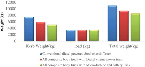
At present, the quantities of traveller transports have increased immensely and that has significantly raised the uses of fuel and therefore, puts an adverse effect on the environment by producing an enormous amount of flue gas (Cunha and Kyprianidis Citation2012). Researchers are concerned about this alarming issue and trying to develop systems, which may able to diminish the destructive ecological effect and increase fuel efficiency. Micro gas turbine system can be a substantial option, which can solve this issue due to its light weight and efficiency. Due to the use of Micro gas turbine the kerb weight and the total weight of the vehicle reduces (). Because of this weight reduction, the fuel consumption will be less than diesel and gasoline-based reciprocating system.
Figure 1. Weight comparison of MGT system with other diesel-based systems (Tan et al, Citation2017; Verstraete and Bowkett Citation2015; Duan et al. Citation2017).
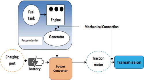
Micro gas turbines are minimal burning turbines with a power output of around 25 kW to 500 kW. They have a wide field of use including car and truck turbochargers, helper control units for planes and jet engines. Contrasted with other power generated innovations they give various potential points of interest. The powertrain of the vehicle for which different parameters are determined is exposed in . For range extender electric vehicle (REEV), the powertrain combines a thermal powertrain and an electrical powertrain. An energy converter and an electric generator are linked with the thermal powertrain called auxiliary power unit (APU). Once the battery is exhausted APU is used to boost the battery and the essential power to overcome the driving load is supplied by the electric powertrain. The APU working speed is kinematically decoupled from the vehicle velocity and the energy converter operating point is convenient to assemble its pre-eminent efficiency.
Figure 2. Power train configuration of MGT-based range extender vehicle.
Several works have been done in the last few years on MGT-based vehicles. (Tan et al. Citation2017) did an analytical and experimental investigation on MGT-based range extender for Asian cities. The authors found that the operating range of the vehicle is greatly reduced when driving in Malaysian urban drive cycle. (Verstraete and Bowkett Citation2015) examined the effect of heat transfer on MGT performance and evaluated it for different conditions. The configuration and selection of material are also discussed in that paper. A developed and instantaneous power control system for MGT is presented in (Duan et al. Citation2017). In that paper, the power compensation of MGT is evaluated for different frequency range. The correction and feasibility analysis of the proposed controlled strategy is validated by simulation results. Different parameters of Semi-Constant volume combustion for micro gas turbine are examined in (Leonard Citation2017). In that paper, for increasing the efficiency the nozzle guide vane is chocked at the first stage. From the analysis, the authors found that the combustor pressure ratio of 1.27 is possible by this system. Investigation of MGT for range extender electric vehicle is analysed in (Karvountzis – Kontakiotis et al. Citation2018). The authors mainly analysed the performance and fuel consumption of MGT-based range extender to see how competitive the system in comparison with diesel and petrol-based vehicle. In that paper, these parameters are analysed taking the small type of vehicle in mind. In research (Grimm et al. Citation2017), a liquid fuel combustor based on the FLOX MGT burner concept for range extender is discussed for next-generation cars. ANSYS 16.1software is used for the CFD simulation for two-phase flow. The combustor characterisation is performed at high-pressure optical test rig.
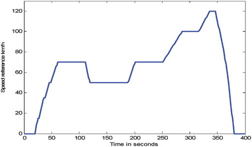
From literature, it is seen that several works have been done using micro gas turbine system, but the system is not yet well established in case of implementing in range extender medium-heavy vehicle. Several works on performance, fuel consumption, compressor, and turbine efficiency and emissions are found, but information on acceleration driving parameters, the sensitivity of battery and weight, use of cooler with turbine and compressor, etc., are not found in the literature. In present years, the uses of Micro gas turbines have increased because of the usage of more accurate systems and plan techniques. However, there are a couple of specialised and non-specialised boundaries to the usage of this technology and the market potential is one of the indispensable one (Somehsaraei and Assadi Citation2018; Pilavachi Citation2002). Besides, all of these issues, a micro gas turbine system can be a significant option which may use in the medium-heavy vehicle instead of conventional engines. In this paper, the Micro gas turbine system for a medium heavy vehicle (bus, truck) is investigated. Fuel consumption and sensitivity analysis is accomplished and compared with other conventional systems. Moreover, a custom drive cycle is simulated using Simulink software (). The simulation was done to see how the acceleration varies with time if the throttle valve remains wide open. Because of using cooler the proposed system is more efficient, extend the range of travel and more environment friendly than other systems as a result of low carbon emission, large battery capacity, and less fuel consumption. The power draw associated with electric vehicle heating and electrical accessories is predicted to lead to a decrease in range of 40% (W. J. Sweeting, Hutchinson, and Savage Citation2011). Mainly this paper focused on numerical analysis of acceleration driving parameters, the sensitivity of battery and weight, use of cooler with turbine and compressor. An investigation of emission characteristics at different humidity level are also analysed in this paper considering two demanding conditions – with turbine inlet cooler and without turbine inlet cooler and results are compared with other established systems where necessary.
Figure 3. Urban part of modified European drive cycle.
2. Mathematical modelling
The most remarkable frequency of micro-turbine system is high and mostly 50000–120000 rpm. Usually, a micro gas turbine device has an efficiency of 15–20%, however, the use of a heat recovery system with it tends to raise the efficiency around 46% in single cycle and 41% in combined cycle (Anonymous Citation2002). In the present modelling, the compressor is treated as an algebraic block, which will help to calculate the real dynamic effects of the system. The combustion chamber is modelled as an algebraic block as well (Stefano et al. Citation2017). The mass and energy balance of the combustion chamber are:
where Mf is the fuel mass flow rate, characterised by its temperature Tf at the chamber inlet and its lower heating value (LHVf) is evaluated at the Tref (reference) temperature.
The pressure drop in the chamber is given in a dimensionless form:
where λcc is a constant coefficient relation to Mx and rated conditions.
In case of turbine, the fundamental physical quantities are illustrated in (Saravanamuttoo et al. Citation2009; Hall and Dixon Citation2013; Stefano et al. Citation2017; Boyce Citation2011; Ordys et al. Citation2012; Soares Citation2011; Najjar and Al-Absi Citation2015). The discussed quantities are interrelated by the following formulas:
where T3 is the exhaust gas inlet and T4” is the outlet temperature; Bt is pressure ratio, P3 is inlet pressure; ȠT is adiabatic efficiency; Pt mechanical power; Cpeg_T is the exhaust gas specific heat.
The pressure at the turbine inlet is expressed by EquationEquation (6)(6)
(6) :
Where
Where. * Means dimensionless number (7)
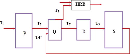
shows the temperature information diagram, which describes all the equations and concepts of temperature profile discussed above. Q represents the air and exhaust gas temperature at the recuperator outlet (T2 and T5) as a function of T4” and T4 from S. Whereas, R represents EquationEquation (2)(2)
(2) .
Figure 4. Temperature information of the system, adapted from (Stefano et al. 2017).
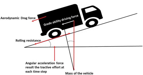
In case of modelling vehicle performance, it is necessary to calculate the tractive force. It is the force applied between the tire and the road surface to move the vehicle. In usual cases, the maximum tractive force depends on two parameters: weight of the vehicle and the adhesion coefficient between the road surface and the tire. As the weight and the adhesion coefficient increase more tractive force can be applied to the wheel without causing slip. represents the forces acting on the vehicle while the vehicle is in motion.
For calculating maximum tractive force EquationEquation (9)(9)
(9) can be used (Beith Citation2011; Lee et al. Citation2001; Karvountzis – Kontakiotis et al. Citation2018; Juarado et al., Citation2008).
The simulation for electric motor is done by the following EquationEquation (10)(10)
(10) .
Figure 5. Schematic diagram of uphill driving.
3. Materials & method
The basic properties of the MGT for which different parameters are evaluated are given in . For sensitivity and fuel consumption, the simulation has been done by Simulink platform, where the quasistatic approach is used. The simulation idea was given by Henrique E Cunha (Cunha and Kyprianidis Citation2012). This is not the best effort performance analysis method; rather it assumes that the vehicle meets the actual speed trace defined by the drive cycle. The initial simulation block is shown in and Detect overload/over speed block is represented in .
Table 1. Data sheet of the MGT.
Engine inertia parameter is very important in determining the amount of acceleration force imposed on the vehicle. The inertia is verified by the addition of an auxiliary torque that is quite proportional to the engine acceleration and inertia. In detect overload and over-speed section, some limitations are taken into consideration. Combustion engines have limitations regarding rotational speed combination/output torque. As soon as they reach their maximum value simulation is stopped. In fuel consumption block, fuel properties are given. Lights and fans are considered in the auxiliary part as they increase fuel consumption due to their power demand. Detect idle block refers to a situation when both rotational speed and torque values drop below a certain limit, the idle speed is detected. In such a case, fuel consumption is equal to a predetermined value. In detect idle section, idle fuel consumption value 0.601 g/s is input, it is activated when the output shaft torque is zero.
Figure 6. Micro-turbine block.
Figure 7. Detect overload/over speed block.
3.1. Estimated fuel consumption
It is obligatory to identify the mass of the generator to find out the fuel consumption of the vehicle (truck). The mass of the generator can be anticipated from the following EquationEquation (11)(11)
(11) (Hill tech developments LTD Citation2000; Zwyssig et al. Citation2005; Tüysüz Citation2010; Benchaim et al. Citation2015). shows various values of ɥ (specific mass) depending on efficiency and speed.
Table 2. Determination of ɥ from efficiency and speed (Pesaran Citation2002; Benchaim et al., Citation2015).
Mass of the engine is calculated from the following EquationEquation (12)(12)
(12) .
In case of hybrid vehicle, the engine efficiency is maximum at all the time (estimating). The equation (Ben Chaim, Shmerling, and Kuperman Citation2015) for hybrid vehicle fuel consumption per 100 Km is:
where Ƞemax is the maximum engine efficiency. However, shows the parameters and values used in calculating the fuel consumption.
Table 3. Parameters and values used in calculating fuel consumption (Ben Chaim, Shmerling, and Kuperman Citation2015).
3.2. Emission characteristics at different humidity level
In this section, for simulation ‘Virtual engine- gas turbine’ software is used. The software provides a facility for conducting a simulation in changing all the necessary parameters and also provides a benefit of conducting a simulation in new (fresh) and old (used) type gas turbine. First, a new turbine is taken and results are obtained for validating the software and also the results are compared with a diesel engine of the same capacity. Then, the results for an old (when system efficiency becomes half) MGT are obtained in two demanding conditions.
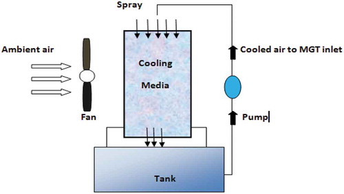
The emission characteristics of MGT are evaluated for different relative humidity. The output of the turbine and the ambient temperature are kept constant to 80 kW and 30°C. The emissions for NOx and CO are determined by varying the relative humidity from 60% to 100%. The emission characteristics are determined with turbine inlet cooling and without turbine inlet cooling. For turbine inlet cooling, the evaporative cooling technique is used and the performance of the evaporator cooler is used is 85%. The evaporative cooler is a wetted firm media, where water is disseminated throughout the header and where air passes from side to side of the wet porous face. Due to this, part of the water is evaporated, absorbing the sensible heat from the air and raising its relative humidity. Though the wet-bulb temperature is not affected, the air dry-bulb temperature is decreased (Johnson Citation1989; Dos Santos, Andrade, and Zaparoli Citation2012). It uses a wetted honeycomb-like medium to exploit the evaporative surface area and cooling effect ().
Figure 8. Architecture of the evaporative cooling system.
4. Results & discussion
4.1. Fuel consumption
Using EquationEquation (13)(13)
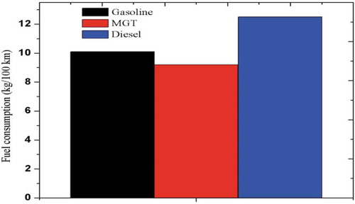
(13) , and the estimated fuel consumption is found. From , it is clear that for per 100 km, Diesel consumption is higher than gasoline and MGT-based system. Moreover, the consumption of gasoline is also higher than the working fluid required running the micro gas turbine. Energy efficiency could be obtained by different methods, among which one can mention waste heat recovery, combined cycles, using energy storage for peak shifting and load levelling (Jubeh and Najjar Citation2007) and widening the range of fuel specifications to improve thermo economics (Najjar and Al-Absi Citation2015). In Micro gas turbine, recuperated units work as a heat exchanger to recover the heat from exhaust steam and transfer heat to the incoming air before combustion. So, the inlet air is being preheated and for this reason, less fuel is needed to raise the temperature to the required at turbine inlet as shown in . So, it can be concluded that modern Micro gas turbine engine shows a better result than the diesel or gasoline engine in terms of fuel consumption. This is also occurred due to the reduction of vehicle mass after using MGT instead of internal combustion reciprocating engine.
Figure 9. Simple cycle micro gas turbine diagram, adapted from (Boukhanouf Citation2011).
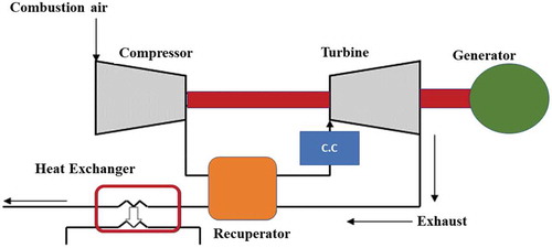
Figure 10. Estimated fuel consumption.
4.2. Acceleration driving cycle
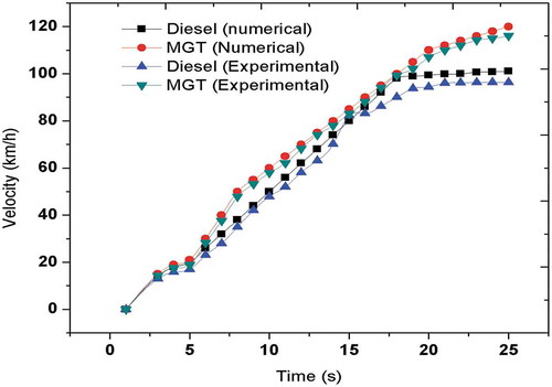
Based on trial and error method, it was possible to achieve a driving pattern capable of making the vehicle operate too close to its maximum capacity without reaching the overloading condition. The study tried to roughly access the dynamic performance of the vehicle. The simulation was done at the demanding condition. The vehicle speed vs. time graph is shown because it is estimated that the vehicle runs at its maximum capacity without reaching overload condition. The drive cycle is also affected by another parameter: The throttle response of the Micro-turbine. The proposed vehicle reaches its nominal output shaft speed within 11 sec approximately after pressing the acceleration paddle, whereas the diesel vehicle takes 16 seconds (). The examined micro gas turbine is a recuperated () one, so that as a result of constant pressure micro gas turbine gives optimal speed and as well as more efficiency than other conventional engines. It is likewise important to state that in these dynamic tests the contact between the tires and the street was not considered. The increasing speed times considered in these simulations were such that issues about the vehicle traction in the asphalt ought not to emerge. Experimental and numerical analysis value comparison is shown in . The analysis shows that in 25 seconds, diesel engine runs approximately 100 km/h, where MGT runs approximately 120 km/h. The experimental results of the diesel engine and turbine are extracted from (Hall Cesare Citation2013; Boyce Citation2011; Soares Citation2011; Ordys et al. Citation2012; Jurado, Ortega, and Cano Citation2008) and the software itself.
Figure 11. Acceleration driving cycle shows how speed varies with time.
4.3. Emission characteristics
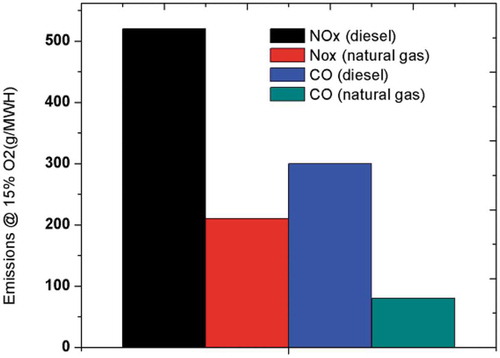
and compare emissions information between an internal combustion diesel engine and a micro gas turbine. In , the emissions of diesel engine is shown at different conditions such as without control and using selective catalytic reduction (SCR) and in , emissions of micro gas turbine is shown in two different conditions. Without a post-combustion system, such as, an exhaust system, ICE engines can have high emission levels ; Do Nascimento et al. Citation2013). Emission levels of micro-turbines are lower than the emission levels of internal combustion diesel engines, as micro-turbines combustion is a non-stop procedure which takes into account an entire burning.
Figure 12. NOX emission of internal combustion engine (new engine).
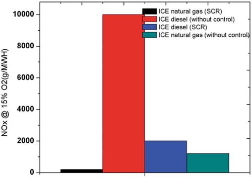
Figure 13. CO and NOX condition of micro-turbine (new engine).
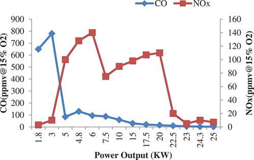
In case of new turbine, if natural gas is used as a fuel in micro-turbine then the CO and NOx emissions at different power output for a micro gas turbine is shown in . The combustion occurs in three significant different steps. The initial step is the start-up to 5 kW, then, the second step is from 5 kW to 20 kW and the final step is the rest. From analysis it is seen that in the first 2 steps, CO formation decreases and NOx formation increases and in last step, lean-premix condition occurs and NOx formation tends to reduce. Both the emissions of CO and NOx experienced a downward trend while power output crosses the value of 20 kW.
Figure 14. CO and NOx emissions of a natural gas micro-turbine (new engine).
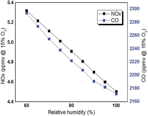
The emission characteristic is greatly affected by the relative humidity. With the increase of relative humidity, the NOx emission of the MGT is decreased, though the CO emission is rapidly increased (). When using evaporative turbine inlet cooling the emission characteristic is quite different. In case of turbine inlet cooling, due to increasing the relative humidity, both the NOx and CO formation reduces (). The system cools through humidification raising relative humidity. Comparing the results of both conditions, it is seen that due to the use of turbine cooler the formation of CO and NOx is comparatively less. In these tests, the output (80 kW) and temperature (30 OC) is kept constant. Above the output of 30 kW in MGT lean premix condition occurs and the emissions tend to reduce. So, the analysis shows that the MGT is much more environment friendly from other system while using turbine cooler.
Figure 15. Emission characteristics without turbine inlet cooling (old engine).
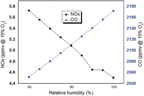
Figure 16. Emission characteristic of MGT with turbine inlet cooling (old engine).
4.4. Sensitivity analysis
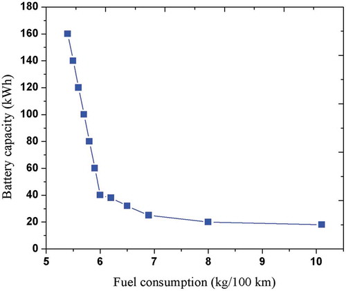
Sensitivity analysis shows how the uncertainty in the output of a system can be apportioned to several types of uncertainty in the input. The major objective of this analysis is to see the impact of vehicle mass or battery capacity on the fuel consumption and performance of the vehicle. The analysis is done taken natural gas as a fuel. From , the fuel consumption in the vehicle increases with the increase of vehicle mass is confirmed. For a vehicle of 8000 kg mass, the fuel consumption is approximately 16 kg for per 100 km; whereas, for 10000 kg, it becomes 19 kg. Here, the battery is the effective power source to run the vehicle in extra range because when the battery capacity is large then the engine will be less used and fuel consumption will significantly reduce. This potential benefit makes difference from other conventional systems. From , it is seen that for a small increase in battery capacity the fuel consumption reduces significantly and for a large battery capacity the fuel consumption reduces in a huge amount and tends to become constant.
Figure 17. Sensitivity analysis for the vehicle mass.
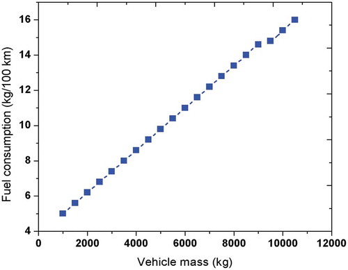
Figure 18. Sensitivity analysis for the battery capacity of the vehicle.
5. Conclusion
MGT provides several potential points of interest for range extender electric vehicles. It reduces fuel consumption by reducing vehicle mass. The major findings of the study are:
It is comparatively easy and effective to balance the unbalanced mass in MGT than other reciprocating systems. The vibration and noise production are also less than other conventional systems. The fuel consumption of MGT vehicle is almost 11.5% lower than conventional diesel vehicles.
MGT-based vehicle accelerates almost twice faster than the diesel-based vehicle at wide open throttle position.
The battery capacity in MGT must be as huge as practical to reduce fuel consumption because as the battery power is depleted the system forces the secondary energy source to provide potential power to run the vehicle. For a battery capacity of 160 kWh, the fuel consumption reduces by almost 40% compared to a 40 kWh battery.
Use of evaporative cooler improves the vehicle performance and reduces emissions and with the increase of relative humidity, the thermal efficiency increases and both CO and NOx formation decreases significantly. Due to the use of inlet cooling system, CO formation reduces by almost 7%.
In this paper, several dynamic parameters were defined and simulated to make a perfect comparison among different power generating unit for a medium-heavy vehicle. In conclusion, it is interesting to mention some future developments of the proposed and discussed method and the research work:
In the acceleration driving cycle, the contact between the tire and the road was not considered, further studies need to be done taking this parameter in consideration.
Changing the type of vehicle may change several results, which may also be a future consideration.
How the variation or improvements of battery characteristics improves the performance of the proposed system, also need to be a future consideration.
Nomenclature
| Symbol | = | Abbreviation & Unit |
| me | = | Engine mass (kg) |
| Hl | = | Calorific value of fuel (j/l) |
| mv | = | Vehicle mass (kg) |
| V1 | = | Speed before acceleration (km/h) |
| mg | = | Generator mass (kg) |
| V2 | = | Speed after acceleration (km/h) |
| ɥ | = | Specific mass (kN/kg) |
| γm | = | Mass factor of the vehicle |
| Vi(t) | = | Instantaneous vehicle speed at subinterval I (km/h) |
| ηt | = | Mechanical drive train efficiency |
| Ti | = | i-th subinterval duration (s) |
| ρf | = | Fuel density (kg/l) |
| fr | = | Rolling resistance coefficient |
| TE | = | Tractive force (N) |
| CD | = | Aerodynamic drag coefficient |
| Η | = | Overall efficiency of power train |
| ρa | = | Air density (kg/m3) |
| Ng | = | Transmission ratio |
| Af | = | Vehicle frontal area (m2) |
| Na | = | Driving axle ratio |
| G | = | Acceleration of gravity (m/s2) |
| R | = | Tire rolling radius |
| ρg | = | Average density of rotor material (g/cm3) |
| Φ | = | Adhesion coefficient between tire and road surface |
| C | = | Torque per volume constant (N.m/cm3) |
| Wr | = | Vehicle weight component on the driving wheel |
| N | = | Engine rotational speed (rpm) |
| KC | = | Copper loss coefficient(.35) |
| Ƞe | = | Engine efficiency |
| Ki | = | Iron loss coefficient (.015) |
| P | = | Engine power (W) |
| T | = | Mean brake effective torque |
| C | = | Constant loss coefficient (600) |
| HRB | = | Heat recovery base |
Subscripts
| T | = | Temperature |
| eg | = | Exhaust gas |
| f | = | Fuel |
| CC | = | Combustion chamber |
| LHV | = | Lower heating value |
Disclosure statement
Authors have no conflict of interest.
Additional information
Notes on contributors
Md Arman Arefin
Md Arman Arefin completed his B.Sc. in Mechanical Engineering from Rajshahi University of Engineering & Technology. His research Interests include biofuels, emission control, and hybrid photovoltaic thermal system. Currently, he is working on a waste to energy project.
Khodadad Mostakim
Khodadad Mostakim is currently studying at Rajshahi University of Engineering & Technology. His research Interests include diesel engine and micro gas turbine system, electric and hybrid vehicle, and energy systems. Currently, he is working on a hybrid PVT system project.
References
- Anonymous. 2002. “Gas Turbines Breaking the 60% Efficiency Barrier.” deCentralized Energy. Accessed 25 April 2017.
- Armstrong, J. L. (2017), “Investigation of Semi‐Constant Volume Combustion for Micro Gas Turbines.” Master’s thesis, University of Sydney.
- Beith, R., Ed. 2011. Small and Micro Combined Heat and Power (CHP) Systems: Advanced Design, Performance, Materials and Applications. Editors: R Beith, Hardcover ISBN: 9781845697952, eBook ISBN: 9780857092755, Imprint: Woodhead Publishing.
- Ben Chaim, M., E. Shmerling, and A. Kuperman. 2015. “A Fuel Efficiency Evaluation of Gas-Turbine-Engine-Based Hybrid Vehicles.” International Journal of Green Energy 12 (4): 328–332. doi:10.1080/15435075.2013.838959.
- Ben Chaim, M., E. Shmerling, and A. Kuperman. 2015. “A Fuel Efficiency Evaluation of Gas-Turbine-Engine-Based Hybrid Vehicles.” International Journal of Green Energy12 (4): 328–332. doi: 10.1080/15435075.2013.838959
- Boukhanouf, R. 2011. “Small Combined Heat and Power (CHP) Systems for Commercial Buildings and Institutions.” In Small and Micro Combined Heat and Power (CHP) Systems, 365–394. Woodhead Publishing Series in Energy.
- Boyce, M. P. 2011. Gas Turbine Engineering Handbook. Elsevier.
- Bracco, S., and F. Delfino. 2017. “A Mathematical Model for the Dynamic Simulation of Low Size Cogeneration Gas Turbines within Smart Microgrids.” Energy 119: 710–723. doi:10.1016/j.energy.2016.11.033.
- Bracco, S., and F. Delfino. 2017. “A Mathematical Model for the Dynamic Simulation of Low Size Cogeneration Gas Turbines within Smart Microgrids.” Energy119: 710–723. doi: 10.1016/j.energy.2016.11.033.
- Cunha, H. E., and K. G. Kyprianidis. 2012. “Investigation of the Potential of Gas Turbines for Vehicular Applications”, in ASME Turbo Expo 2012: Turbine Technical Conference and Exposition.” American Society of Mechanical Engineers: 51–64.
- Do Nascimento, M. A. R., L. de Oliveira Rodrigues, E. C. Dos Santos, E. E. B. Gomes, F. L. G. Dias, E. I. G. Velásques, and R. A. M. Carrillo. 2013. “Micro Gas Turbine Engine: A Review.” In Progress in Gas Turbine Performance. IntechOpen. doi: http://dx.doi.org/10.5772/54444.
- Dos Santos, A. P. P., C. R. Andrade, and E. L. Zaparoli. 2012. “Comparison of Different Gas Turbine Inlet Air Cooling Methods.” World Academy of Science, Engineering and Technology 61: 40–45.
- Duan, J., S. Fan, F. Wu, L. Sun, and G. Wang. 2017. “Power Balance Control of Micro Gas Turbine Generation System Based on Supercapacitor Energy Storage.” Energy 119: 442–452. doi:10.1016/j.energy.2016.12.063.
- Grimm, F., J. M. Lourier, O. Lammel, B. Noll, and M. Aigner (2017, June), “A Selective Fast Fourier Filtering Approach Applied to High Frequency Thermoacoustic Instability Analysis.” In ASME Turbo Expo 2017: Turbomachinery Technical Conference and Exposition, V04AT04A015. American Society of Mechanical Engineers, Charlotte, North Carolina, USA. doi: https://doi.org/10.1115/GT2017-63234.
- Hall, C., and S. L. Dixon. 2013. Fluid Mechanics and Thermodynamics of Turbo Machinery. Butterworth-Heinemann, Elsevier, ISBN: 978-1-85617-793-1, doi: https://doi.org/10.1016/C2009-0-20205-4.
- Hill tech developments LTD. 2000. Use of micro turbine generators in hybrid electric vehicles.
- Johnson, R. S. 1989. “The Theory and Operation of Evaporative Coolers for Industrial Gas Turbine Installations.” Journal of Engineering for Gas Turbines and Power 111 (2): 327–334. doi:10.1115/1.3240257.
- Jubeh, N., and Y. S. H. Najjar. 2007. “Comparison of Performance of a Cascaded Humidified Advanced Turbine (CHAT) with Combined Gas Turbine Engine.” International Journal of Sustainable Energy 26 (4): 209–220. doi:10.1080/14786450701679449.
- Jurado, F., M. Ortega, and A. Cano. 2008. “Predictive Control of Matrix Converter-based Micro-turbine.” Electric Power Components and Systems 36 (4): 409–431. doi:10.1080/15325000701658532.
- Karvountzis - Kontakiotis, A., A. M. Andwari, A. Pesyridis, S. Russo, R. Tuccillo, and V. Esfahanian. 2018. “Application of Micro Gas Turbine in Range-Extended Electric Vehicles.” Energy 147: 351–361. doi:10.1016/j.energy.2018.01.051.
- Lee, Y. B., H. D. Kwak, C. H. Kim, and G. H. Jang. 2001. “Analysis of Gas-lubricated Bearings with a Coupled Boundary Effect for Micro Gas Turbine.” Tribology Transactions 44 (4): 685–691. doi:10.1080/10402000108982511.
- Najjar, Y. S. H., and S. Al-Absi. 2015. “Sustainable Gas Turbine Power Generation by Adopting Green Control Technologies.” International Journal of Sustainable Engineering 8 (4–5): 250–257. doi:10.1080/19397038.2013.865812.
- Ordys, A. W., A. W. Pike, M. A. Johnson, R. M. Katebi, and M. J. Grimble. 6 December 2012. “Modelling and Simulation of Power Generation Plants.” Springer Science & Business Media,ISBN: 978-1-4471-2114-5. https://www.springer.com/gp/book/9781447121169.
- Pesaran, A. A. 2002. “Battery Thermal Models for Hybrid Vehicle Simulations.” Journal of Power Sources 110 (2): 377–382. doi:10.1016/S0378-7753(02)00200-8.
- Pilavachi, P. A. 2002. “Mini-and Micro-gas Turbines for Combined Heat and Power.” Applied Thermal Engineering 22 (No18): 2003–2014. doi:10.1016/S1359-4311(02)00132-1.
- Saravanamuttoo, H. I. H., G. F. C. Rogers, H. Cohen, and P. Straznicky. 2009. Gas Turbine Theory. 6 ed. Edinburgh Gate, England: Pearson Education Limited.
- Soares, C. 2011. Microturbines: Applications for Distributed Energy Systems. Elsevier, Butterworth-Heinemann, ISBN: 0080549489 and 9780080549484.
- Somehsaraei, H. N., and M. Assadi. 2018. “Micro-Scale Combined Heat and Power: Contributor to Sustainable Energy Solution.” Sustainable Energy Technology and Policies. Springer, Singapore. 105–130. https://doi.org/10.1007/978-981-10-8393-8_4
- Sweeting, W. J., A. R. Hutchinson, and S. D. Savage. 2011. “Factors Affecting Electric Vehicle Energy consumption.” International Journal of Sustainable Engineering 4 (3): 192–201. doi:10.1080/19397038.2011.592956.
- Tan, F. X., M. S. Chiong, S. Rajoo, A. Romagnoli, T. Palenschat, and R. F. Martinez-Botas. 2017. “Analytical and Experimental Study of Micro Gas Turbine as Range Extender for Electric Vehicles in Asian Cities.” Energy Procedia 143: 53–60. doi:10.1016/j.egypro.2017.12.647.
- Tüysüz, A., A. Looser, J. W. Kolar, and C. Zwyssig. (2010), “Novel Miniature Motors with Lateral Stator for a Wide Torque and Speed Range.” In IECON 2010-36th Annual Conference on IEEE Industrial Electronics Society, 1741–1747. doi:10.1109/IECON.2010.5675418
- Tüysüz, A., A. Looser, J. W. Kolar, and C. Zwyssig. (2010), “Novel Miniature Motors with Lateral Stator for a Wide Torque and Speed Range.” In IECON 2010-36th Annual Conference on IEEE Industrial Electronics Society, Glendale, AZ, USA. 1741–1747. doi: 10.1109/IECON.2010.5675418
- Verstraete, D., and C. Bowkett. 2015. “Impact of Heat Transfer on the Performance of Micro Gas Turbines.” Applied Energy 138: 445–449. doi:10.1016/j.apenergy.2014.10.075.
- Weston, F., N. L. Seidman, and C. James. 2001. “Model Regulations for the Output of Specified Air Emissions from Smaller-scale Electric Generation Resources.” Obtido via internet www. raponline.org
- Zwyssig, C., J. W. Kolar, W. Thaler, and M. Vohrer. (2005), “Design of a 100 W, 500000 Rpm Permanent-magnet Generator for Mesoscale Gas Turbines.” In Industry Applications Conference. Fourtieth IAS Annual Meeting. Conference Record of the 2005, Kowloon, Hong Kong, China 1, 253–260. doi: 10.1109/IAS.2005.1518318