
 ?Mathematical formulae have been encoded as MathML and are displayed in this HTML version using MathJax in order to improve their display. Uncheck the box to turn MathJax off. This feature requires Javascript. Click on a formula to zoom.
ABSTRACT
The effect of partial replacement of coarse aggregate by plastic waste on the performance of concrete under impact three-point bending loading was investigated experimentally and numerically. Specimens were prepared for 5%, 10% and 20 % replacements by volume of coarse aggregate. For each case, three beams of 100 mm wide, 50 mm deep and 400 mm long were loaded to failure in a drop-weight impact machine by subjecting it to 30 N weight from 400 mm height, while another three beams of the same size were tested under static load. The load-displacement of beams of concrete with plastic waste subjected to static and impact loads were studied. The dynamic beam behaviour was also analysed numerically using the finite-element method (FEM) based LUSAS software. In general, the experimental results reveal that the impact tup, inertial load and bending load increase with the increase in the percentage of coarse aggregate replacement by plastic waste, while the static peak bending load always decreases. The concrete with plastic waste is stronger and more energy-absorbing under impact loading, than under static loading. The predicted load against displacement behaviours of both ordinary concrete and concrete with plastic waste, are well matched with the experimental results.
1. Introduction
Disposal of waste plastic is a serious environmental issue all around the globe, on account of its health hazard and difficulty in land filling. The high cost of disposal and the requirement of large landfill area often result in random and illegal dumping of waste plastic. Hence, there is an urgent need to identify alternative solutions to reuse the plastic waste for other applications, and concrete has been identified to be one of the feasible options (Siddique, Khatib, and Kaur Citation2008; Saikia and de Brito Citation2012). This is in line with fundamental environmental strategies; prevention of waste, recycling of waste materials, escaping landfill, energy regaining from waste, and saving raw materials (Bhardwaj and Kumar Citation2017). On the other hand, the concrete has limited properties such as low tensile strength, low ductility, and low impact energy absorption (Akçaözoğlu, Atis, and Akçaözoğlu Citation2010). There are many concrete components and structures subject to impact loads, for instance, wall panels, bridge decks, hydraulic structures, and industrial floors, airport pavements, highway paving. Therefore, higher resistance to impact loads and load carrying capacity are required in this kind of applications (MoEU Citation2012). In regards to the said matter, Mohammadhosseini, Abdul Awal, and Mohd Yatim (Citation2017) reported that fibre reinforced composites have the ability to address the brittleness of concrete. Utilisation of waste metalised plastic fibres in the production of concrete has revealed possibility towards the sustainable and green construction with a benefit of the harmless alternative of waste plastics disposal. In their studies, Mohammadhosseini, Tahir, and Sam (Citation2018) worked on the reinforced concrete with waste metalised plastic fibres. They found that adding these waste fibres could have significant effects on development of strength and impact resistance of concrete composites.
Different types of plastic have been investigated these last years: polyethylene terephthalate (PET), high-density polyethylene (HDPE) and polypropylene (PP). These studies have focussed on the effect of plastic addition in the workability of the fresh composites and in the mechanical strength of the hardened mixtures (Sobhan and Mashna Citation2002).
Ismail and AL-Hashmi (Citation2008) have found that, as the percentage of waste plastic (consists of 80% polyethylene and 20% polystyrene) increases, the workability increases and the bulk density decreases. This last result is due to the low density of plastic aggregates comparing to conventional ones. Naik et al. (Citation1996) have found that post-consumer waste HDPE plastic can be successfully used in concrete as soft filler. They have shown that chemical treatment has a significant effect on performance of the plastic filler in concrete. AL-Manaseer and Dalal (Citation1997) stated that concrete containing plastic aggregates from car bumpers has more ductile behaviour than similar types of concrete made with conventional aggregates. This ductile behaviour could be very advantageous in minimising crack formation in concrete structures. Also, the compressive strength and the splitting tensile strength of the concrete decreased when the amount of plastics aggregates increased.
Al-Tayeb et al. (Citation2013) have investigated the effect of partial replacement of sand by 5%, 10% and 20 % of rubber waste on the impact resistance of the beams. The results reveal that the impact tup increase by 39% with 20% sand replacement by plastic waste, while the static peak bending load always decreases. Gholipour, Zhang, and Mousavi (Citation2018); Gholipour, Zhang, and Mousavi (Citation2019) and Zhang, Gholipour, and Mousavi (Citation2019) also have investigated the effect of dynamic load on the RC structure.
In this study the effect of replacement of coarse aggregate by 5%, 10% and 20% of plastic waste on the load-displacement and fracture energy of the beams subjected to impact load was investigated experimentally, and the results were compared with those under static load and those obtained by finite-element method (FEM) simulations using Lusas programme. The authors claim the following contributions to the present work:
Study of impact load, the resulting displacement, and fracture energy, of concrete with plastic waste.
Numerical simulation to study the load-displacement behaviour of concrete with plastic waste particles, using FEM; in fact simulation study on concrete plastic waste particles has not been reported so far.
2. Materials and methods
2.1. Materials
In this study, ordinary Portland cement (OPC) (ASTM Type I) was used. The cement chemical compositions are shown in .
Table 1. Chemical compositions of cement
Concrete with 45MPa compressive strength was prepared as the controlled mix.
The maximum coarse aggregate size was 10 mm, the bulk density and specific gravities of coarse aggregates were 1780 kg/m3 and 2.64, respectively. Normal silica sand; its bulk density and specific gravity are 1730 kg/m3 and 2.65, respectively, at ambient temperature and moisture. Polycarbonate (PW) – particles obtained from industrial waste was used in this study. The particle size distributions of coarse and plastic aggregates are given in . represents photographs of PW-aggregates. Their physical and mechanical properties are presented in .
Table 2. Particle size distribution of coarse and PC plastic aggregates
Table 3. Physical and mechanical properties of plastic aggregates
Concrete mixes were prepared with replacements of coarse aggregate volume by 5, 10, and 20% (PW 5%, PW 10%, and PW 20%) with the plastic waste of particle size 4–5 mm. The composition of the ordinary concrete and the concrete with plastic waste are presented in . shows the image of plastic waste, (relative density, 1.2), used in the present study.
Figure 1. Images of the plastic waste sample
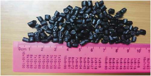
Table 4. Constituents of ordinary concrete and concrete with plastic waste
For the compression and modulus of elasticity test, three cylinders of 200 mm height and 100 mm diameter were used for each type at the age of 28 days. In the case of three-point impact flexural loading test, three beams of each type of mixtures were prepared. The testing beams were 50 mm deep, 100 mm wide and 400 mm long, with a loaded span of 300 mm. Another three beams of the same size were prepared for each case, for three-point static flexural loading test. All specimens were cured in water for 28 days in accordance with ASTM C 192/C192M (Citation2006).
2.3. Experimental set-up and procedure
The compressive stress and static modulus of elasticity were tested according to ASTM C 39 (Citation2001) and ASTM C 469 (Citation1994) respectively, and the three-point static flexural strength tests were conducted according to ASTM C78 (Citation1994). Instrumented falling-weight impact machine are used as . The machine had 4 kg hammer which could be dropped from variable heights of up to 2 m; in the present experiments, the hammer was dropped from a height of 0.6 m. The impact-force history during the test was measured using a piezo-electric load cell with 100 kN capacity, located just above the impactor tup. The specimens were supported by two steel cylinders of 20 mm diameter, fixed on movable right angled supports. The specimen accelerations during an impact were recorded by an accelerometer with a range of ±2500 g (g is gravitational acceleration) and sensitivity 2 mV/g. near the edge at the mid-span. The accelerometer was glued on the top of the beam at mid-span near the edge while the drop hammer was located at the centre. Data from the load cell and the accelerometer were recorded at intervals of 0.2 µs, using a PC-based data acquisition system.
Figure 2. The experimental impact flexural test rig. (a) impact flexural test rig [21]. (b) Cylinders supported and load cell
![Figure 2. The experimental impact flexural test rig. (a) impact flexural test rig [21]. (b) Cylinders supported and load cell](/cms/asset/7c8b142c-4b91-43b2-86a3-159edbcb54d9/tsue_a_1774820_f0002_b.gif)
The bending load (Pb) at the mid-span of the beam is given by Banthia (Citation1987) and Banthia et al. (Citation1989):
where Pt is the tup load, and Pi (EquationEquation 2(2)
(2) ) is the inertial load which is uniform along the beam, for linear distribution of accelerations.
where ρ: mass density of concrete; A: area of cross-section of the beam; a: acceleration at the centre; L: span of the test beam; and ov: length of the overhang. The displacement history d (t) at the load-point is given by Banthia (Citation1987):
where a(t) is the acceleration as function of time.
2.4 Finite element formulation
In order to simulate the behaviour of plastic concrete beams subjected to the impact load, LUSAS was used. The concrete beam was represented by eight corners of hexahedron elements () using standard shape functions as represented by EquationEquation (4)(4)
(4) (Oñate Citation2009). The corresponding shape functions for the eight nodes of the hexahedron are summarised in .
Figure 3. The 8-node hexahedron and the natural coordinates ξ, η, ζ
Table 5. The shape functions for 8-node hexahedron
The deformation was calculated by using the following expression:
where {u}: the deformation vector at any location over the element; {ui}: the deformation vector at the specified node of the element; [Ni]: the nodal shape function matrix of size (3 × 3); np: the total number of the nodes in the element.
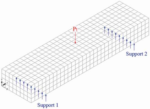
The boundary conditions () were set as: The tup load curve obtained from experiment was used to define the load at the location Pt (x = 200 mm, y = 50 mm, z = 50 mm), and the beam was supported (uniformly distributed along z-direction) from bottom at locations, x = 50 mm (support 1) and x = 350 mm (support 2). To choose the appropriate mesh size, a number of trials were made and found that, after 1024 elements there was no improvement in accuracy; hence this mesh size was selected and the simulation took about 30 minutes in a computer with dual-Core Processor i7-7500U 2.7 Ghz, 8GB DDR4 Memory, 1TB Hard Drive, USB 3.0
Figure 4. Finite element model for the beam
The nonlinear dynamic equilibrium equation (Chopra Citation2007) is given by:
where a is acceleration, v is velocity, d is distance, fe is the force and M is the mass matrix which is defined as:
where N is the element shape function array and ρ is the density matrix. C is the Rayleigh damping matrix expressed by:
where K is the structure stiffness matrix defined by:
where B is the strain displacement matrix and D is material modulus matrix; aR (EquationEquation 10(10)
(10) ) and bR (EquationEquation 11
(11)
(11) ) are the Rayleigh damping coefficient of mass and stiffness respectively.
where and
are the damping ratio of the structure for first circular frequency (
) and second circular frequency (
) respectively (LUSAS 14 Citation2006). The damping ratio for first circular and second circular frequencies is assumed as 5% (Chopra Citation2007). Explicit (central difference) nonlinear dynamic scheme was used to determine the acceleration and thus the velocity and displacement increments for each time step. Explicit scheme is used for problems which require small time steps such as shock response from explosive or impact loading (LUSAS 14 Citation2006).
The central difference algorithm implemented in LUSAS 14 (Citation2006) is as follows:
For each time step n
where a, v and d are the acceleration, velocity and displacement of any node.
For numerical stability, LUSAS itself computes the time step.
3. Results and discussion
3.1 Experimental results
The compressive stress and modulus of elasticity of the different mixes of concrete with and without the plastic waste were obtained.
shows the average compressive strength of concrete. As the coarse aggregate is replaced by plastic waste, the average compressive strength reduces by 5, 7 and 21% with 5, 10 and 20% of volumes of coarse aggregate replacement respectively. Similar is the case of elastic modulus which reduces by 6, 12 and 18%. The reduction in compressive strength and modulus of elasticity with the addition of plastic waste to the concrete as coarse aggregate replacement is also consistent with the earlier investigations AL-(AL-Manaseer and Dalal Citation1997). The reduction of compressive strength of concrete is attributed to the weak compressive strength of the plastic compared to the compressive strength of the coarse aggregate. In addition to that the weak bond between plastic particles and the cement paste and the deformability of the plastic particles, which result in the initiation of cracks around the plastic particles in a fashion similar to that, occur in normal concrete due to air voids, cause a reduction in strength.
Table 6. Compressive strength and modulus of elasticity of concrete
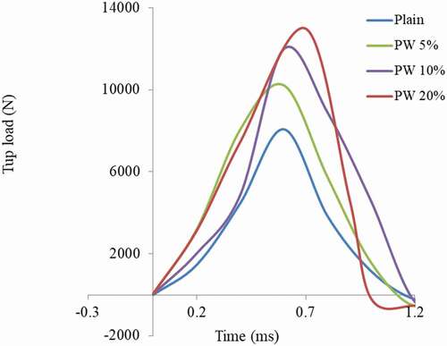
presents the tup load history, which determine by the load cell, which indicates that the peak amplitude of the tup load increases by 26%, 48%, and 60% with replacements of 5%, 10%, and 20% respectively, of coarse aggregate volume by plastic waste.
Figure 5. Tup load history
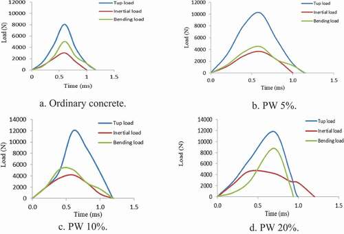
show the history of tup load, inertial load and bending load for ordinary concrete with the three types of plastic concrete specimens. The results show that both the inertial load and bending load increase with the increasing amount of coarse aggregate replaced by plastic waste.
The inertial load increases because plastic increases the flexibility of the composite mix. According to Fu, Erki, and Seckin (Citation1991) and Suaris (Citation1983) lower the static bending strength higher the relative increase in the bending strength with increase in strain rate. In addition to that Al-Tayeb et al. (Citation2017) concluded that, increase of plastic improves the ductility and the ability to absorb the impact load. These two reasons together improve the impact bending resistance. On the other hand, the increases in impact load may be because under impact loading the cracks are forced to propagate through short distance which usually has plastic with higher damping and aggregates with higher strength than concrete.
Figure 6. Histories of Tup, inertial, and bending loads. (a) Ordinary concrete. (b) PW 5%. (c) PW 10%. (d) PW 20%
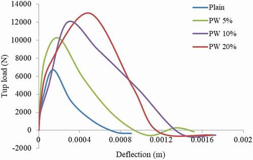
shows the calculated impact bending load against deflection for the ordinary and the three types of plastic concretes. In this article, the fracture energy is defined as the area under impact bending load vs. displacement curve (Banthia et al. Citation1989). concludes the fracture energies for the ordinary and plastic concretes. The dynamic fracture energy is higher than static fracture energy as also observed in ref. (Banthia et al. Citation1989). The fracture energy of the ordinary concrete under impact load is 1.4 Nm. Under impact load the flexural energy of concrete increase with the increase amount of coarse aggregate replaced by plastic waste, with 5% and 10% plastic waste is higher than that of the ordinary concrete under the same condition by 77% and 115%, while a drastic increase of 201% is noticed with 20% replacement.
Figure 7. Impact bending load against deflection
3.2. Comparison of dynamic and static test results
is the comparison between static and impact bending test results. Generally the static peak bending load is less than the impact peak bending load, as also reported in previous works (Banthia et al. Citation1989) that used ordinary concrete as control mix. The results show that the ratio between dynamic and static peak bending loads increases with the increase of coarse aggregate replacement by plastic waste; this is because the static bending load decreases with increase of coarse aggregate replacement by waste plastic while it is reverse for impact bending load. Addition of plastic waste to concrete decreases its strength under static load but the ability of plastic particles to absorb dynamic energy enhances the strength of concrete under impact load.
Table 7. Comparison of experimental static and impact bending test results
3.3 Comparison of experimental and simulation results
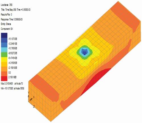
The comparison of experiment and simulation for impact load vs. displacement of ordinary and plastic waste concrete specimens are shown in which indicate good matching. shows that at the end of impact response of the ordinary concrete, the predicted and experimental displacements are 1.0 mm and 0.8 mm respectively. The respective displacements increase with the increase of coarse aggregate replacement by plastic waste and reaches to 1.5 mm and 1.6 mm as shown in . On the other hand shows the fracture FEM patterns of plastic concrete specimens which is the same experiment pattern. Thus it can be deduced that the proposed FEM model is excellent in handling the problem under investigation.
Figure 8. Experimental and predicted impact load vs. displacement. (a) Ordinary concrete. (b) PW 5%. (c) PW 10%. (d) PW 20%
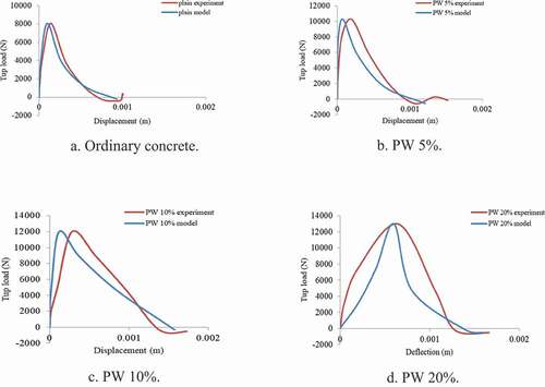
Figure 9. FEM patterns
4. Conclusion
The influence of polycarbonate at various volume fractions ranging from 5% to 20% on compressive strength and impact resistance of concrete was investigated experimentally. The following are the conclusions drawn out of the results found and the observations made in this study.
The compressive strength of the plastic concrete, in general, decreased with the increase in plastic content. As the coarse aggregate is replaced by plastic waste, the average compressive strength reduces by 21% with 20% of volume replacement.
It has been experimentally demonstrated that the impact tup, inertial load and bending load of cement concrete increased with the increase in the percentage of coarse aggregate replacement by plastic waste; however the static peak bending load always decreased. Under impact load the flexural energy of concrete with 20% plastic waste is higher than that of the ordinary concrete under the same condition by 201%.
Accelerometer could be used successfully to measure both the displacement and inertial loading effects in the instrumented impact tests.
It was also proved that the proposed finite FEM modelling and simulation by using LUSAS could excellently predict the load against displacement behaviour of both ordinary and plastic concretes. The present numerical technique would be a promising breakthrough in this area, as it solves most of the issues associated with the tedious, risky and costly experimental procedures involved, and provides realistic and accurate predictions.
Disclosure statement
No potential conflict of interest was reported by the authors.
Additional information
Notes on contributors
Mustafa M. Al-Tayeb
Abdullah M. Zeyad, Assistant Professor of structural engineering at the department of civil engineering, college of engineering, Jazan University (JU). I received PhD in structural Engineering from Universiti Sinice Malaysia (USM) in 2013. I have many research works related concrete technology, concrete structures, supplemental cementitious materials, and smart materials &structures. I am a reviewer for some international journals.
Abdullah M. Zeyad
Mustafa m. Altayeb, Associate Professor at Civil Engineering Department at Palestine University, Gaza, Palestine. Currently, I am Head of Civil Engineering Department. My research interests are in the areas of eco-friendly construction materials. I have many research works related to reuse of industrial waste product at a high replacement of cement or other contents of concrete to produce eco-friendly concrete. I have an extensive experience in both academic and practice in many fields of civil engineering; I have published many papers in international journals with high impact factors. I have presented many papers at several international conferences. I am a reviewer for many international journals.
Osama Dawoud
Osama Dawoud, an assistant professor at the Civil Engineering Department, College of Engineering, Istinye University, Turkey. I received PhD in Civil Engineering from University of Cambridge (UoC), UK in 2015. I have research interests in the field of sustainable construction materials, and cementation of granular materials. I am a reviewer for some international journals.
B. A. Tayeh
Bassam A. Tayeh, Associate Professor at Civil Engineering Department at Islamic University of Gaza (IUG), Gaza, Palestine. Currently, I am Head of Civil Engineering Department. My research interests are in the areas of UHPFC, eco-friendly construction materials. I have many research works related to reuse of industrial waste product at a high replacement of cement or other contents of concrete to produce eco-friendly concrete. I have an extensive experience in both academic and practice in many fields of civil engineering; I have published many papers in international journals with high impact factors. I have presented many papers at several international conferences. I am a reviewer for many international journals.
References
- Akçaözoğlu, S., C. D. Atis, and K. Akçaözoğlu. 2010. “An Investigation on the Use of Shredded Waste PET Bottles as Aggregate in Lightweight Concrete.” Waste Management 30 (2): 285–290. doi:https://doi.org/10.1016/j.wasman.2009.09.033.
- AL-Manaseer, A. A., and T. R. Dalal. 1997. “Concrete Containing Plastic Aggregates.” Concrete International 19 (8): 47–52.
- Al-Tayeb, M. M., B. A. Bakar, H. Ismail, and H. M. Akil. 2013. “Effect of Partial Replacement of Sand by Recycled Fine Crumb Rubber on the Performance of Hybrid Rubberized-normal Concrete under Impact Load: Experiment and Simulation.” Journal of Cleaner Production 59: 284–289. doi:https://doi.org/10.1016/j.jclepro.2013.04.026.
- Al-Tayeb, M. M., H. Ismail, O. Dawoud, S. R. Wafi, and I. Al Daoor. 2017. “Ultimate Failure Resistance of Concrete with Partial Replacements of Sand by Waste Plastic of Vehicles under Impact Load.” International Journal of Sustainable Built Environment 6 (2): 610–616. doi:https://doi.org/10.1016/j.ijsbe.2017.12.008.
- American Society for Testing and Materials (ASTM) C192/192. 2006. “Standard Practice for Making and Curing Concrete Test Specimens in the Laboratory, Vol. 4.02.” West Conshohocken, PA, USA.
- American Society for Testing and Materials (ASTM) C39/C39. 2001. “Test Method for Compressive Strength of Cylindrical Concrete Specimens.” Pennsylvania: Annual Book of ASTM Standards.
- American Society for Testing and Materials (ASTM) C469. 1994. “Standard Test Method for Static Modulus of Elasticity and Poisson’s Ratio of Concrete in Compression.” Pennsylvania: Annual Book of ASTM Standards.
- American Society for Testing and Materials (ASTM) C78. 1994. “Standard Test Method for Flexural Strength of Concrete (Using Simple Beam with Third-point Loading).” West Conshohocken, PA: ASTM International.
- Banthia, N. 1987. “Impact Resistance of Concrete.” PhD thesis, University of British Columbia, Vancouver, B.C., Canada.
- Banthia, N., S. Mindess, A. Bentur, and M. Pigeon. 1989. “Impact Testing of Concrete Using a Drop-weight Impact Machine.” Experimental Mechanics 29 (1): 63–69. doi:https://doi.org/10.1007/BF02327783.
- Bhardwaj, B., and P. Kumar. 2017. “Waste Foundry Sand in Concrete: A Review.” Construction and Building Materials 156: 661–674. doi:https://doi.org/10.1016/j.conbuildmat.2017.09.010.
- Chopra, A. K. 2007. Dynamics of Structures: Theory and Application to Earthquake Engineering. 3rd ed. Prentice-Hall.
- Fu, H., M. Erki, and M. Seckin. 1991. “Review of Effects of Loading Rate on Concrete in Compression.” Journal of Structural Engineering 117 (12): 3645. doi:https://doi.org/10.1061/(ASCE)0733-9445(1991)117:12(3645).
- Gholipour, G., C. Zhang, and A. A. Mousavi. 2018. “Effects of Axial Load on Nonlinear Response of RC Columns Subjected to Lateral Impact Load: Ship-pier Collision.” Engineering Failure Analysis 91: 397–418. doi:https://doi.org/10.1016/j.engfailanal.2018.04.055.
- Gholipour, G., C. Zhang, and A. A. Mousavi. 2019. “Loading Rate Effects on the Responses of Simply Supported RC Beams Subjected to the Combination of Impact and Blast Loads.” Engineering Structures 201: 109837. doi:https://doi.org/10.1016/j.engstruct.2019.109837.
- Ismail, Z. Z., and E. A. AL-Hashmi. 2008. “Use of Waste Plastic in Concrete Mixture as Aggregate Replacement.” Waste Management 28 (11): 2041–2047. doi:https://doi.org/10.1016/j.wasman.2007.08.023.
- LUSAS 14. 2006. “Theory Manual Volume 1.” FEA Ltd., V.14.0.3. Surrey, UK.
- MoEU. 2012. “Information Received during the Eionet Consultation of the Paper, Email of 14 November 2012 from Arzu Nuray.” Turkish Ministry of Environment and Urbanisation.
- Mohammadhosseini, H., A. S. M. Abdul Awal, and J. B. Mohd Yatim. 2017. “The Impact Resistance and Mechanical Properties of Concrete Reinforced with Waste Polypropylene Carpet Fibres.” Construction and Building Materials 143: 147–157. doi:https://doi.org/10.1016/j.conbuildmat.2017.03.109.
- Mohammadhosseini, H., M. M. Tahir, and A. R. M. Sam. 2018. “The Feasibility of Improving Impact Resistance and Strength Properties of Sustainable Concrete Composites by Adding Waste Metalized Plastic Fibres.” Construction and Building Materials 169: 223–236. doi:https://doi.org/10.1016/j.conbuildmat.2018.02.210.
- Naik, T. R., S. S. Singh, C. O. Huber, and B. S. Brodersen. 1996. “Use of Post-consumer Waste Plastics in Cement-based Composites.” Cement and Concrete Research 26 (10): 1489–1492. doi:https://doi.org/10.1016/0008-8846(96)00135-4.
- Oñate, E. 2009. Structural Analysis with the Finite Element Method. Linear Statics, Volume 1: Basis and Solids (Lecture Notes on Numerical Methods in Engineering and Sciences). Springer.
- Saikia, N., and J. de Brito. 2012. “Use of Plastic Waste as Aggregate in Cement Mortar and Concrete Preparation: A Review.” Construction and Building Materials 34: 385–401. doi:https://doi.org/10.1016/j.conbuildmat.2012.02.066.
- Siddique, R., J. Khatib, and I. Kaur. 2008. “Use of Recycled Plastic in Concrete: A Review.” Waste Management 28 (10): 1835–1852. doi:https://doi.org/10.1016/j.wasman.2007.09.011.
- Sobhan, K. H., and M. Mashna. 2002. “Tensile Strength and Toughness of Soil–Cement–Fly-Ash Composite Reinforced with Recycled High-Density Polyethylene Strips.”.Journal of Materials in Civil Engineering 14 (2): 177–184. doi:https://doi.org/10.1061/(ASCE)0899-1561(2002)14:2(177).
- Suaris, W. 1983. “Properties of Concrete Subjected to Impact.” Journal of Structural Engineering 109 (7): 1727. doi:https://doi.org/10.1061/(ASCE)0733-9445(1983)109:7(1727).
- Zhang, C., G. Gholipour, and A. A. Mousavi. 2019. “Nonlinear Dynamic Behavior of Simply-supported RC Beams Subjected to Combined Impact-blast Loading.” Engineering Structures 181: 124–142. doi:https://doi.org/10.1016/j.engstruct.2018.12.014.