
 ?Mathematical formulae have been encoded as MathML and are displayed in this HTML version using MathJax in order to improve their display. Uncheck the box to turn MathJax off. This feature requires Javascript. Click on a formula to zoom.
ABSTRACT
A biomass waste producer gas has a good potential as renewable sources fuel of either spark ignition (SI) or compression ignition (CI) engine. Several biomass wastes have been utilised as a feedstock of gasification process to produce producer gas. High heating value and low tar content producer gas should be obtained in biomass gasification. The producer gas has to be cleaned up to remove tar when it is used for the engines. The present paper aims to review a thermo-chemical conversion of a biomass into a producer gas, tar removal method and utilisation of a producer gas as fuel of internal combustion engine. Many previous published works are studied, cited and summarised in the present work. The review indicates that performance of a gasifier is affected by gasifier design and operating parameters, i.e. feedstock properties and size, gasification medium, equivalence ratio and gasification temperature. Tar removal can be approached using primary or secondary technique. Modification of the intake system of either SI or CI engine is required when the engine is fuelled with a producer gas.
1. Introduction
To overcome a shortage of crude oil based fuel, many works in searching an alternative and renewable fuel for internal combustion (IC) engine have been performed around the world. Several alternative and renewable fuels have been successfully tested on IC engine by many researchers, such as Ethanol-Gasoline blend (Chen and Nishida Citation2014; Costa and Sodré Citation2011; Doğan et al. Citation2017; Eyidogan et al. Citation2010; Schifter et al. Citation2011; Thakur et al. Citation2017; Yao, Tsai, and Wang Citation2013), Biogas (Qian et al. Citation2017; Porpatham, Ramesh, and Nagalingam Citation2018; Karagöz et al. Citation2018; Jatana et al. Citation2014; Nunes et al. Citation2017; Zhang et al. Citation2018; Reddy, Aravindhan, and Mallick Citation2016; Verma, Das, and Kaushik Citation2017), Liquid Petroleum Gas (Çinar et al. Citation2016; Gumus Citation2011; Masi Citation2012) and Methyl Ester (Pina et al. Citation2017; Anggarani et al. Citation2015). Other promising alternative and renewable fuel is a biomass producer gas. A producer gas is a combustible gas generated from biomass gasification in the reactor named gasifier.
Generally, wastes from agricultural and forestry are used as a biomass feedstock of gasifier. Fuel parameter of the producer gas like composition, heating value and tar content depend on biomass sources, gasifier design, gasification medium and operating parameter. shows a route of biomass energy conversion based on gasification. Product of gasification, raw producer gas, can be used directly as a fuel of a burner for heating purpose or as a fuel of IC engine after tar cleaning process. Many researchers around the globe have been working on investigation the use of producer gas as a fuel of IC engine. Mostly, they instigated the performance of a compression ignition (CI) engine fuelled with the producer gas. Their works evaluated the performance of the producer gas engine at various engine’s operating parameters. The performance of the engine evaluated are power output, torque output, specific fuel consumption and exhaust gas pollutant.
Figure 1. A route of gasification based biomass energy conversion system
Several review papers in the area of gasification have been published. However, none of those articles discussed gasification-IC engine system. In order to build up the system, it is important to have a comprehensive knowledge regarding gasification, producer gas properties and operating parameter of IC engine. Thus, this paper aims to report a literature review on a thermo-chemical conversion of a biomass into a producer gas, tar removal method and gasifier-IC engine system. Many previous published works in related area are studied, cited and discussed.
2. Biomass gasification
2.1. Feedstock properties
Prior to be used as a feedstock of gasification, it is important to perform proximate and ultimate analysis to obtain thermochemical properties of the biomass waste. Proximate analysis gives composition of the biomass, i.e. volatile matter (VM), fixed carbon (FC), moisture (MC) content and ash content (ASH). Whereas, ultimate analysis provides typical elemental weight fraction of carbon (C), hydrogen (H), oxygen (O) and nitrogen (N). Woody biomass or non-woody biomass can be converted into producer gas through gasification. The wastes of biomass from agricultural, forestry and wood processing industries, are potential sources of the feedstock, such as rice husk, pine sawdust, neem wood, olive bagasse, vine pruning and many others. Properties of biomass feedstock are an essential parameter in biomass gasification. Proximate and ultimate properties of the feedstock affect a characteristic of the producer gas. The important characteristics of the producer gas are gas composition, heating value and tar content. summarises the properties of several used biomasses as the feedstock of gasification.
ar = as received; adb = dry basis; wb = wet basis
Table 1. Summarise the properties of several used biomasses in gasification
No specific standard of proximate and ultimate analysis available for specific biomass waste. However, the tests can be performed using ASTM Standard for wood fuel and ASTM Standard for Refused Derived Fuel (RDF). presents the ASTM Standards that can be applied for proximate and ultimate analysis of biomass waste which is adapted from Basu (Citation2010).
Table 2. ASTM Standard for biomass fuel analysis (Basu Citation2010)
If LHV of the feedstock is required in analysis, following equation can be use to calculated the LHV of the feedstock (Basu Citation2010):
where the higher heating value of the feedstock is indicated by HHVf, the latent heat of water vapour is indicated by hw (2260 kJ/kg). Meanwhile, H and M represent the percentage of hydrogen and moisture content of the feedstock, respectively.
2.2. Type of gasifier
Basu (Citation2010) divided a reactor of gasifier into fixed bed, fluidised bed and entrained flow. Depend on relative flow direction between a feedstock and a producer gas in the reactor, the fixed bed reactor is further classified into downdraught, updraught and cross-draft (Basu Citation2010; Guangul, Sulaiman, and Ramli Citation2012; Vyarawalla et al. Citation1984). Meanwhile, there are two type of fluidised bed reactors (i.e. bubbling and circulating fluidised bed). shows classification of gasifier reactor and a schematic diagram of flow direction of a feedstock, a gasification medium (air) and a producer gas which are cited from Guangul, Sulaiman, and Ramli (Citation2012).
In the updraught gasifier, a feedstock is loaded into the reactor from the top and gasification medium is introduced from below. The producer gas exits at upper part of the reactor. The feedstock flow in opposite direction with the product gas. Meanwhile, both the feedstock and the producer gas flow descending in downdraught type and the producer gas exits the reactor below the grate. Gasification medium is supplied either from top or upper part of the reactor. Meanwhile in a cross-draft gasifier, inlet of gasification medium and outlet of producer gas are placed in opposite side of the reactor. The fluidised bed gasifier uses the concept of fluidisation, in which makes solid particles look like a fluid. Typically, fluidised medium are hot air and water vapour. The gasification process occurs when hot fluidised material contacts with the feedstock. Lastly, an entrained flow gasifier is used for gasification of very fine particles (size < 100 µm) and operated at high temperature and pressure ranges from 20 to 50 bar (Basu Citation2010). Pros and drawbacks of each reactor are summarised in .
Figure 2. Classification of gasifier reactor
Table 3. Pros and drawbacks of each reactor
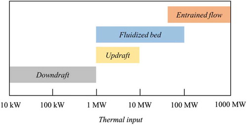
Depends on thermal input capacity, fixed bed reactor is more suitable for small capacity plant especially downdraught reactor (Gai and Dong Citation2012; Reed and Das Citation1988; Sheth and Babu Citation2009). The thermal input of downdraught reactor is in the range of 10 kW to 1 MW, updraught reactor is in the range of 1–10 MW, fluidised bed rector is in the range of 1–100 MW, and entrained flow reactor is up to 1000 MW as shown in .
Figure 3. Thermal input capacity of different gasifier
2.3. Thermo-chemical reactions of gasification
Gasification is a thermo-chemical conversion of solid fuel into a producer gas that occurs in a reactor called gasifier. Gasification is a complex thermo-chemical process involving exothermic and endothermic process. During gasification, the feedstock experiences sequence processes of drying, pyrolysis, oxidation and reduction. General reaction of biomass gasification using gasification medium of air is given by EquationEq. (2(2)
(2) )
where n is the molar number of the feedstock, x, y, z and k are the percentage of carbon, hydrogen, oxygen and nitrogen from ultimate analysis of the feedstock, m is the molar number of gasification medium (air), ø is the equivalence ratio of gasification, x1–x5 are the percentage of hydrogen, carbon monoxide, carbon dioxide, methane and nitrogen in producer gas. The composition of those gases in the producer gas is analysed using gas chromatograph.
Gasification initiates at combustion zone where partial and complete oxidation occur. Some amount of heat is released from this exothermic reaction. More heat is released by complete oxidation. 394 kJ/mol heat is generates by complete oxidation and only 111 kJ/mol heat is produced by partial oxidation. Heat from combustion is used for drying, pyrolysis and reduction (auto-thermal gasification). In drying process, moisture contents in the feedstock is driven off. The dried feedstock is then subjected to pyrolysis where biomass molecules are decomposed into condensable gases, tar and char in the absence of oxygen at temperatures about 200–700°C. The decomposition of condensable gas into non-condensable gases, liquid and char occurs through homogeneous and heterogeneous reaction. The condensable vapour is cracked into non-condensable permanent gases CO and CO2. Meanwhile, a main gasification reaction is reduction which endothermic reactions (i.e. Bouduard and Water-Gas) and exothermic reactions (Water-Gas Shift and Methane formation) occur. The endothermic reactions use 303 kJ/mol heat and the exothermic reactions release 116 kJ/mol heat (Basu Citation2010). EquationEq. (3)(3)
(3) –EquationEq. (10)
(10)
(10) are the equations of all thermo-chemical reactions involved during gasification.
Partial oxidation
Complete oxidation
Drying
Pyrolysis
Bouduard reaction
Water-gas reaction
Water-gas shift reaction
Methane reaction
2.4. Operating parameters and performance
Besides feedstock properties and gasifier design, various operating parameter such as feedstock size, gasification medium, equivalence ratio and gasification temperature affect performance of gasifier. Performance of gasifier evaluated are producer gas quality and cold gas efficiency (CGE) of the gasifier. Quality of the producer is good when its heating value is high and tar content is low.
2.4.1. Feedstock size
Beside proximate and ultimate properties, feedstock size need to be considered in gasification. Smaller biomass can produce more producer gas when compared to larger biomass for a certain gasification time. The smaller size of the biomass having a larger heat transfer surface area which able to accelerate heat transfer rate, thus increasing the rate of releasing volatiles during the pyrolysis process (Hernández, Aranda-Almansa, and Bula Citation2010). For particular air-fuel ratio, the rate of biomass consumption is higher for smaller size biomass. Reducing biomass size results in faster biomass conversion. A larger biomass tends to slow down the gasification process so less producer gas is produced (Patel, Upadhyay, and Patel Citation2014). Uniform biomass size can also affect the performance of the gasifier (Belonio and Preface Citation2005). The more uniform the size of the biomass, the higher the efficiency of the gasifier.
2.4.2. Gasification medium
Generally, gasifier uses air, steam, or oxygen as medium of gasification. These gasification medium influence calorific value of the producer gas. Gasification using oxygen produces the highest heating value gas. On the other hand, gasification using air generates producer gas with the lowest heating value. Nitrogen presents in the producer gas if air as gasification medium. The present of this inert gas reduce the composition of combustible gases per volume of the producer gas, thus low calorific value producer gas generated (Basu Citation2010). However, air is commonly used as gasification medium due to its availability. presents typical calorific value of the producer gas at different gasification medium.
Table 4. Effect of gasification medium on producer gas heating value (Basu Citation2010)
2.4.3. Equivalence ratio
Equivalence ratio is a ratio between air to fuel ratio stoichiometric and air to fuel ratio actual. Since the gasification is a thermochemical process with very less amount of oxidiser, the equivalence ratio should be more than unity (rich mixture). The equivalence ratio is calculated using EquationEq. (11(11)
(11) )
where ø is the equivalence ratio, [A/F]st and [A/F]act are the air to fuel ratio stoichiometric and the air to fuel ratio actual.
For biomass with ultimate properties of x%C, y%H, z%O, k%N, the [A/F]st can be calculated using EquationEq. (12(12)
(12) )
where x, y, z and k are the mass fraction of C, H, O, N of the feedstock, MWa is the molecular weight of atmospheric air, and MWf is the molecular weight of the feedstock. Mass fraction of x, y, z and k can be obtained from ultimate analysis of the feedstock. Meanwhile, molecular weight of the air and feedstock can be calculated using EquationEq. (13)(13)
(13) and EquationEq. (14
(14)
(14) ), respectively.
When gasifier is operated in batch operation, mass and volume flow rate of gasification air can be obtained using EquationEq. (15)(15)
(15) and EquationEq. (16)
(16)
(16) , accordingly.
where and
are the mass and volume flow rate of the air (kg/s) and (m3/s), mf is the mass of the feedstock (kg), t is operational time (s) and ρa is the air density (kg/m3). Meanwhile, the term of
is defined as the feedstock consumption rate (kg/s).
2.4.4. Temperature of gasification
Temperature of gasification is influenced by equivalence ratio. Temperature of gasification enhances as equivalence ratio decrease. From EquationEq. (11)(11)
(11) it can be shown that more air is used in the gasification with reducing equivalence ratio. More air used means that oxygen availability increases, results in enhancing oxidation process and releasing more heat. At elevated gasification temperature, quality of the producer gas improves. The heating value of producer gas increases with rising gasification temperature is due to percentages of gas H2 and CO in producer gas improve with increasing gasification temperature (Wang et al. Citation2015) and enhancing tar cracking process (Liu et al. Citation2012).
2.4.5. Gasifier performance
Commonly, gasifier performance evaluated are combustible gas composition, LHV, CGE and tar content. The higher percentage of CO, H2 and CH4 in the producer gas, the higher the calorific value of the producer gas. Percentage of CO, H2 and CH4 can be obtained from gas analysis using Gas Chromatograph. The molar fractions of these combustible gas are used to calculate the LHV (Guo et al. Citation2014).
Since LHV is obtained, the CGE is calculated using EquationEq. (18(18)
(18) ) (Guo et al. Citation2014).
where vg is the gas yields (Nm3) and LHVf is the lower heating value of the feedstock
Other indication for performance of gasifier is tar content. Tar amount presents in good quality gas is very less. Typically, downdraught gasifier generates producer gas with low tar content.
3. Tar removal method
3.1. Tar definition
Tar is a blend of condensable hydrocarbons as well as aromatic compounds up to five rings and Polycyclic Aromatic Hydrocarbons (PAHs) (Anis and Zainal Citation2011; Woolcock and Brown Citation2013; Lucia et al. Citation2018). Meanwhile, during the meeting between the International Energy Agency (IEA), the Directorate General for Energy of the European Commission (DG XVII) and the Energy Department of the United States in Brussels 1998, tar has been declared as all hydrocarbons with molecular weight higher than benzene (Lucia et al. Citation2018). Tar formation is due complex thermochemical reactions, like chemolysis, depolymerisation, oxidation, polymerisation and cycloaddition. Tar generation is afected by various factors, such as reaction conditions, reactor configurations and feedstock type (Yu et al. Citation2014). Tar is undesirable in the producer gas, especially in gasifier-engine system. Tar is toxic, carcinogenic and corrosive. Producer is disallowed direct utilisation in internal combustion engine due to corrosive property of the tar (Pallozzi et al. Citation2018). Blocking and contaminating of a fuel line, a filter, and an engine may occurs by the tar (Zhai et al. Citation2015). Thus, tar removal is very important task in gasifier-engine system. Milne, Evans, and Abatzaglou (Citation1998) recommended that maximum tar content in producer gas for internal combustion engine was 100 mg/Nm3.
3.2. Classification of tar removal method
Tar cleanup technique was broadly categorised as primary and secondary techniques (Anis and Zainal Citation2011; Paethanom et al. Citation2012). Primary technique removes tar inside the gasifier’s reactor (in-situ) and secondary one removes tar downstream the reactor. Primary cleanup approaches are limited to thermal and catalytic cracking (Woolcock and Brown Citation2013). Thermal cracking tar inside the reactor can be achieved with high gasification temperature. Meanwhile, secondary method can be approached by hot and wet gas treatment (Anis and Zainal Citation2011). These approaches clean producer gas mechanically prior to be used as intended fuel. Gas cleanup method can be aprroached at low temperature so called cod gas cleanup method and at high temperature so called hot gas cleanup method (Abdoulmoumine et al. Citation2015). Cold gas method uses either wet techniques or dry techniques, such as scrubbing technique (i.e. impinging, spraying and bubbling) and wet electrostatic precipitators or cyclones at room temperature or below. Due to its simplicity in construction and operation, has low pressure-drop, and low cost investment, the scrubber is widely used in gasifier-engine system.
3.3. Tar removal scrubber
The producer gas is passed through the scrubbing material. Depending on scrubbing material, scrubber can be categorised as wet and dry scrubber as shown in . In wet scrubber, liquids is used as scrubbing material. On the other hand, solid material is used as scrubbing material in dry scrubber. Further, wet scrubber can be approached with impinging, spray, and venturi scrubber. shows schematic diagram of flow configuration between producer gas and liquid in impinging, spray, and venturi scrubber. Producer gas is impinged to the scrubbing liquid in the vessel. Tar condenses when contact with the liquid and adsorbed by the liquid. In spray scrubber, producer gas flows upward and liquid is spread in an opposite direction. The spray scrubber requires pump to generate the spray. Meanwhile, producer gas is injected into the scrubbing liquid stream in venturi scrubber. In other to enhance adsorption surface area, microbubble venturi scrubber has been developed and tested (Unyaphan et al. Citation2017a, Citation2017b). The scrubbing liquids have been use are water (Phuphuakrat, Namioka, and Yoshikawa Citation2011; Bhave, Vyas, and Patel Citation2008), waste palm oil (Ahmad and Zainal Citation2016), vegetable oil (Unyaphan et al. Citation2017a; Phuphuakrat, Namioka, and Yoshikawa Citation2011), diesel fuel, biodiesel fuel and engine oil (Unyaphan et al. Citation2017a). The type of scrubbing material has a significant effect on adsorption efficiency. According to Phuphuakrat, Namioka, and Yoshikawa (Citation2011), the adsorption efficiency can be ranked from the highest to the lowest such that diesel fuel, vegetable oil, biodiesel fuel, engine oil and water. Meanwhile, various solid materials have been used as adsorbent of dry scrubber, such as chestnut wood char (Paethanom et al. Citation2013) and bio-char (Shen et al. Citation2016).
Figure 4. Classification of tar removal scrubber
Figure 5. Schematic diagram of flow arrangement between producer gas and liquid
3.4. Gravimetric tar measurement
Gravimetric tar measurement aims to figure out mass of tar per unit volume of producer gas (g/Nm3) neglecting tar component. Tar measurement system basically consists of sampling probe, an impingement bottle, and sampling line as given in a schematic diagram in . The diagram shows a gas preconditioning module from CEN’s Technical Report (Good et al. Citation2005), the impingement bottle equipment, and the sampling line from Son et al. (Citation2011). The sampling probe is inserted in mainstream of the producer gas. Tar sampling method is classified as isokinetic method and non-isokinetic method. The isokinetic method is more complex and requires calculation to obtain proper diameter of nozzle probe. The velocity of producer gas entering the nozzle has to be equal to mainstream velocity. Meanwhile, a non-isokinetic method can be adopted for rough measurement. The non-isokinetic method is more freely in selection of nozzle probe diameter. The nozzle probe is inserted in opposite direction to producer gas mainstream.
The impingement bottle has a function of collecting the tar by means of condensation and absorption. The equipment consists of a train of bottles filled with Isopropanol, ice-water container, a salt-dry ice container. The producer gas is by-passed from mainstream line to the sampling line. The sampling line consists of tube, gas metre, and vacuum pump. Tar in the producer gas condenses when contacting with Isopropanol. The sampling line should be made as short as possible. The gas metre measures producer gas flow rate. After tar sampling, the Isopropanol is then heated up in an electrical oven till 50°C. The Isopropanol evaporates and any substances remaining is defined as tar. The tar is then weighted to obtain tar content in producer gas.
Figure 6. Gravimetric tar measurement equipment
4. Gasifier-engine system
Because a producer gas is a product of biomass waste gasification, the producer gas is got more attention as fuel of Internal Combustion (IC) engine nowadays. The gas has been explored as a fuel of either SI engine (Indrawan et al. Citation2017; Nadaleti and Przybyla, Citation2018; Tsiakmakis et al. Citation2014) or CI engine (Singh, Singh, and Pathak Citation2017; Ramadhas, Jayaraj, and Muraleedharan Citation2008; Yaliwal et al. Citation2016). Energy content in a blend of producer gas-air is about 30% lower than energy of gasoline-air blend, thus producer gas engine losses at minimum power loss at any given engine’s speed since power output of the engines is directly related to fuel-air mixture energy. The use of 30% producer gas as secondary fuel in 62.5 kW gen-set diesel engine, thermal efficiency of the engine decreased about 8% (Dhole et al. Citation2014). Peak cylinder pressure after the combustion phase lower on the producer additional than that on diesel alone. The heat release rate in the first phase of combustion was observed decrease when the use of additional producer gas (Dhole, Lata, and Yarasu Citation2016). Average reduction of 63.62% in HC emission was achieved in CI engine fuelled with producer gas (Lal and Mohapatra Citation2017). SI engine has higher thermal efficiency than HCCI engine about 3.5% (Przybyla et al. Citation2016). Combustion duration in HCCI engine on average was four times shorter than the combustion duration of the SI engine. Overall efficiency of 75 kWe Genset-CI engine using producer gas was 21% at 85% load (Raman and Ram Citation2013). The efficiency of the producer gas engine is affected by adiabatic flame temperature of the fuel-air mixture. The highest temperature of the mixture about 1800 K. Whereas, heating value of the gas was 5.6 MJ/Nm3 at stoichiometric air-fuel ratio of 1.2 and 6.0 MJ/Nm3 at air-fuel ratio of 1.3 (Raman and Ram Citation2013). Better engine performance and exhaust emission (except NOx) was achieved when H2 content in the producer gas was high, especially under leaner condition (Roy et al. Citation2009).
Modification of the intake system of either SI or CI engine is required when the engine is fuelled with a producer gas. Reed and Das (Citation1988) used the gas mixer to replace the liquid-fuel carburettor. The gas mixer behaves like liquid-fuel carburettor in which the producer gas and atmospheric air mix in correct ratio. Venturi type gas mixer with throat diameter of 25 mm was used to supply proper mixture of producer gas and air required for the engine (Homdoung, Tippayawong, and Dussadee Citation2015). The producer gas mixer must mix a proper ratio of air with the producer gas, approximately a 1:1 ratio of fuel to air by volume (Reed and Das Citation1988). Since the composition of a producer gas fluctuates during the process, the combustion properties of the producer gas also alter that affect performance of the engine. In order to an effective operation of the engine. Babu, Clement, and Rajan (Citation2019) proposed the air-gas regulator (AGR) for a 2.2 kW engine. This regulator aimed to regulate the amount of fuel flow according to engine load. The regulator was attached before the carburettor. To support required engine load, an adequate port diameter has to be appropriate selected for ensuring sufficient fuel flow. The required air-fuel ratio is set in carburettor. Many gasifier- IC engine systems have been successfully developed worldwide. Roy, Datta, and Chakraborty (Citation2013) and Zainal et al. (Citation2002) reported their work in developing gasifier-engine system fed by furniture waste and wood chip, respectively. Meanwhile, a small-scale rice husk gasifier-IC engine system has been reported by Yoon et al. (Citation2012).
5. Conclusion
Many previous published works in the area of biomass gasification are studied, cited, and discussed, it can be concluded that:
Biomass gasification is a promising renewable energy conversion technology to utilise biomass energy into useful producer gas for internal combustion engine.
Besides gasifier design, performance of a gasifier is affected by various operating parameters, i.e. feedstock size and properties, gasification medium, equivalence ratio, and gasification temperature. Performance of a gasifier can be evaluated in terms of combustible and heating value of a producer gas, tar content in a producer gas and cold gas efficiency of a gasifier.
Typically, a downdraught gasifier produces a low tar content producer gas. However, tar removal is still required when a producer gas is used as a fuel of internal combustion engine. Tar content in a producer gas must less than 100 mg/Nm3 when a producer gas is used for fuelling an internal combustion engine
Tar removal of a producer gas can be done by primary method or secondary method. Primary method removes a tar inside the gasifier’s reactor (in-situ) and secondary method removes a tar downstream the reactor.
Modification of an intake system of either a Spark Ignition or a Compression Ignition engine is required when the engine is fuelled with a producer gas. In order to get proper mixing between a producer gas and an atmospheric air, a liquid-fuel carburettor is replaced by a gas mixer or by attaching air-gas regulator before the carburettor.
Acknowledgements
The authors sincerely thank to DRPM-RISTEK/BRIN, Kementerian Riset dan Teknologi/Badan Riset dan Inovasi Nasional (Ministry of Research and Technology/Board of National Research and Innovation) of Republic of Indonesia for the funding support under the program of Penelitian Dasar Unggulan Perguruan Tinggi (PDUPT) year of 2020.
Disclosure statement
No potential conflict of interest was reported by the authors.
Additional information
Funding
Notes on contributors
A. A. P. Susastriawan
A.A.P. Susastriawan is an Assistant Professor in Department of Mechanical Engineering Institut Sains & Teknologi AKPRIND Yogyakarta. He completed his doctoral study from Department of Mechanical & Industrial Engineering Universitas Gadjah Mada in 2018. His doctoral research relates with biomass waste gasification. His research areas are biomass gasification & combustion, renewable energy, and alternative fuel for Internal combustion engine.
Yuli Purwanto
Yuli Purwanto is a Lecturer in Department of Mechanical Engineering Institut Sains & Teknologi AKPRIND Yogyakarta. His research areas are energy conversion and fluid mechanic.
Purnomo
Purnomo is an Associate Professor in Department of Mechanical Engineering Institut Sains & Teknologi AKPRIND Yogyakarta since 2018. Previously, he was an Associate Professor in Department of Mechanical & Industrial Engineering Universitas Gadjah Mada. His research interests are combustion, internal combustion engine, and energy conversion.
References
- Abdoulmoumine, N., S. Adhikari, A. Kulkarni, and S. Chattanathan. 2015. “A Review on Biomass Gasification Syngas Cleanup.” Applied Energy 155: 294–307. doi:https://doi.org/10.1016/j.apenergy.2015.05.095.
- Ahmad, N. A., and Z. A. Zainal. 2016. “Performance and Chemical Composition of Waste Palm Cooking Oil as Scrubbing Medium for Tar Removal from Biomass Producer Gas.” Journal of Natural Gas Science and Engineering 32: 256–261. doi:https://doi.org/10.1016/j.jngse.2016.03.015.
- Almeida, A., P. Neto, I. Pereira, A. Ribeiro, and R. Pilão. 2017. “Effect of Temperature on the Gasification of Olive Bagasse Particles.” J. Energy Inst 92(01): 1–8.
- Anggarani, R., C. S. Wibowo, R. Sukaraharja, and R. Sukaraharja. 2015. “Performance and Emission Characteristics of Dimethyl Ether (DME) Mixed Liquefied Gas for Vehicle (LGV) as Alternative Fuel for Spark Ignition Engine.” Energy Procedia 65: 274–281. doi:https://doi.org/10.1016/j.egypro.2015.01.048.
- Anis, S., and Z. A. Zainal. 2011. “Tar Reduction in Biomass Producer Gas via Mechanical, Catalytic and Thermal Methods: A Review.” Renewable and Sustainable Energy Reviews 15 (5): 2355–2377. doi:https://doi.org/10.1016/j.rser.2011.02.018.
- Ayyadurai, S., L. Schoenmakers, and J. J. Hernández. 2017. “Mass and Energy Analysis of a 60 kWth Updraft Gasifier Using Large Size Biomass.” Fuel 187: 356–366. doi:https://doi.org/10.1016/j.fuel.2016.09.080.
- Babu, M. S., S. Clement, and N. K. S. Rajan. 2019. “Adaptation of Air-Gas Regulator for Small Capacity Producer Gas Engine.” Energy Procedia 156: 435–441. doi:https://doi.org/10.1016/j.egypro.2018.11.091.
- Basu, P. 2010. Biomass Gasification and Pyrolysis Handbook. USA: Elsevier .
- Belonio, A. T., and W. Preface. 2005. Rice Husk Gas Stove Handbook. Iloilo City, Philippines: Central Philippine University.
- Bhave, A. G. A., D. K. Vyas, and J. B. Patel. 2008. “A Wet Packed Bed Scrubber-based Producer Gas Cooling – Cleaning System.” Renewable Energy 33: 1716–1720. doi:https://doi.org/10.1016/j.renene.2007.08.014.
- Bhoi, P. R., R. L. Huhnke, A. Kumar, S. Thapa, and N. Indrawan. 2018. “Scale-up of a Downdraft Gasifier System for Commercial Scale Mobile Power Generation.” Renewable Energy 118: 25–33.
- Biagini, E., F. Barontini, and L. Tognotti. 2016. “Development of a Bi-equilibrium Model for Biomass Gasification in a Downdraft Bed Reactor.” Bioresource Technology 201: 156–165. doi:https://doi.org/10.1016/j.biortech.2015.11.057.
- Chen, R., and K. Nishida. 2014. “Spray Evaporation of Ethanol-gasoline-like Blend and Combustion of Ethanol-gasoline Blend Injected by Hole-type Nozzle for Direct-injection Spark Ignition Engines..” Fuel 134: 263–273. doi:https://doi.org/10.1016/j.fuel.2014.05.082.
- Çinar, C., S. Fatih, Ö. Can, and A. Uyumaz. 2016. “A Comparison of Performance and Exhaust Emissions with Different Valve Lift Profiles between Gasoline and LPG Fuels in A SI Engine.” Appl. Therm. Eng 107: 1261–1268. doi:https://doi.org/10.1016/j.applthermaleng.2016.07.031.
- Costa, R. C., and J. R. Sodré. 2011. “Compression Ratio Effects on an Ethanol/gasoline Fuelled Engine Performance.” Applied Thermal Engineering 31: 278–283. doi:https://doi.org/10.1016/j.applthermaleng.2010.09.007.
- Couto, N. D., V. B. Silva, E. Monteiro, A. Rouboa, and P. Brito. 2017. “An Experimental and Numerical Study on the Miscanthus Gasification by Using a Pilot Scale Gasifier.” Renewable Energy 109: 248–261. doi:https://doi.org/10.1016/j.renene.2017.03.028.
- Dhole, A. E., D. B. Lata, and R. B. Yarasu. 2016. “Effect of Hydrogen and Producer Gas as Secondary Fuels on Combustion Parameters of a Dual Fuel Diesel Engine.” Applied Thermal Engineering 108: 764–773. doi:https://doi.org/10.1016/j.applthermaleng.2016.07.157.
- Dhole, A. E., R. B. Yarasu, D. B. Lata, and A. Priyam. 2014. “Effecton Performance and Emissions of a Dual Fuel Diesel Engine Using Hydrogen and Producer Gas as Secondary Fuels.” International Journal of Hydrogen Energy 39: 8087–8097.
- Doğan, B., D. Erol, H. Yaman, and E. Kodanli. 2017. “The Effect of Ethanol-gasoline Blends on Performance and Exhaust Emissions of a Spark Ignition Engine through Exergy Analysis.” Applied Thermal Engineering 120: 433–443. doi:https://doi.org/10.1016/j.applthermaleng.2017.04.012.
- Eyidogan, M., A. N. Ozsezen, M. Canakci, and A. Turkcan. 2010. “Impact of Alcohol – Gasoline Fuel Blends on the Performance and Combustion Characteristics of an SI Engine.” Fuel 89: 2713–2720. doi:https://doi.org/10.1016/j.fuel.2010.01.032.
- Gai, C., and Y. Dong. 2012. “Experimental Study on Non-woody Biomass Gasification in a Downdraft Gasifier.” International Journal of Hydrogen Energy 37 (6): 4935–4944. doi:https://doi.org/10.1016/j.ijhydene.2011.12.031.
- Good, J., L. Ventress, H. Knoef, U. Zielke, P. L. Hansen, W. van de Kamp, P. de Wild, et al. 2005. “Sampling and Analysis of Tar and Particles in Biomass Producer Gases.” Technical Report CEN BT/TF 143:1–44.
- Guangul, F. M., S. A. Sulaiman, and A. Ramli. 2012. “Gasifier Selection, Design and Gasification of Oil Palm Fronds with Preheated and Unheated Gasifying Air.” Bioresource Technology 126: 224–232. doi:https://doi.org/10.1016/j.biortech.2012.09.018.
- Gumus, M. 2011. “Effects of Volumetric Efficiency on the Performance and Emissions Characteristics of a Dual Fueled (Gasoline and LPG) Spark Ignition Engine.” Fuel Processing Technology 92: 1862–1867. doi:https://doi.org/10.1016/j.fuproc.2011.05.001.
- Guo, F., Y. Dong, L. Dong, and C. Guo. 2014. “Effect of Design and Operating Parameters on the Gasification Process of Biomass in a Downdraft Fixed Bed: An Experimental Study.” International Journal of Hydrogen Energy 39 (11): 5625–5633. doi:https://doi.org/10.1016/j.ijhydene.2014.01.130.
- Hernández, J. J., G. Aranda-Almansa, and A. Bula. 2010. “Gasification of Biomass Wastes in an Entrained Flow Gasifier: Effect of the Particle Size and the Residence Time.” Fuel Processing Technology 91 (6): 681–692. doi:https://doi.org/10.1016/j.fuproc.2010.01.018.
- Homdoung, N., N. Tippayawong, and N. Dussadee. 2015. “Performance and Emissions of a Modified Small Engine Operated on Producer Gas.” Energy Conversion and Management 94: 286–292. doi:https://doi.org/10.1016/j.enconman.2015.01.078.
- Indrawan, N., S. Thapa, P. R. Bhoi, R. L. Huhnke, and A. Kumar. 2017. “Engine Power Generation and Emission Performance of Syngas Generated from Low-density Biomass.” Energy Conversion and Management 148: 593–603. doi:https://doi.org/10.1016/j.enconman.2017.05.066.
- Jatana, G. S., M. Himabindu, H. S. Thakur, and R. V. Ravikrishna. 2014. “Strategies for High Efficiency and Stability in Biogas-fuelled Small Engines.” Experimental Thermal and Fluid Science 54: 189–195. doi:https://doi.org/10.1016/j.expthermflusci.2013.12.008.
- Karagöz, M., S. Sar, E. Deniz, and B. Çiftçi. 2018. “The Effect of the CO2 Ratio in Biogas on the Vibration and Performance of a Spark Ignited Engine.” Fuel 214: 634–639. doi:https://doi.org/10.1016/j.fuel.2017.11.058.
- Lal, S., and S. K. Mohapatra. 2017. “The Effect of Compression Ratio on the Performance and Emission Characteristics of a Dual Fuel Diesel Engine Using Biomass Derived Producer Gas.”.” Applied Thermal Engineering 119: 63–72. doi:https://doi.org/10.1016/j.applthermaleng.2017.03.038.
- Lin, K. S., H. P. Wang, C. J. Lin, and C. I. Juch. 1998. “A Process Development for Gasification of Rice Husk.” Fuel Processing Technology 55 (3): 185–192. doi:https://doi.org/10.1016/S0378-3820(98)00049-6.
- Liu, H., J. Hu, H. Wang, C. Wang, and J. Li. 2012. “Experimental Studies of Biomass Gasification with Air.” Journal of Natural Gas Chemistry 21 (4): 374–380. doi:https://doi.org/10.1016/S1003-9953(11)60379-4.
- Lucia, M., V. Rios, A. M. González, E. Eduardo, S. Lora, and O. Agustin. 2018. “Reduction of Tar Generated during Biomass Gasification : A Review.” Biomass & Bioenergy 108: 345–370. doi:https://doi.org/10.1016/j.biombioe.2017.12.002.
- Masi, M. 2012. “Experimental Analysis on a Spark Ignition Petrol Engine Fuelled with LPG (Liquefied Petroleum Gas).” Energy 41 (1): 252–260. doi:https://doi.org/10.1016/j.energy.2011.05.029.
- Milne, T. A., R. J. Evans, and N. Abatzaglou. 1998. Biomass Gasifier ‘“tars”’: Their Nature, Formation, and Conversion, A national laboratory of the U.S. Department of Energy.
- Mubashar, M., A. Munir, M. Ahmad, and A. Tanveer. 2017. “Downdraft Gasifier Structure and Process Improvement for High Quality and Quantity Producer Gas Production.” In J. Energy Inst, 1–11.
- Nadaleti, W. C., and G. Przybyla. 2018. “SI Engine Assessment Using Biogas, Natural Gas and Syngas with Different Content of Hydrogen for Application in Brazilian Rice Industries: Efficiency and Pollutant Emissions.” International Journal of Hydrogen Energy 43: 10141–10154. doi:https://doi.org/10.1016/j.ijhydene.2018.04.073.
- Nunes, M. M., D. Faria, J. P. Vargas, M. Bueno, S. M. M. Elmassalami, and C. R. Pereira. 2017. “Thermodynamic Simulation Model for Predicting the Performance of Spark Ignition Engines Using Biogas as Fuel.” Energy Conversion and Management 149: 1096–1108. doi:https://doi.org/10.1016/j.enconman.2017.06.045.
- Paethanom, A., S. Nakahara, M. Kobayashi, P. Prawisudha, and K. Yoshikawa. 2012. “Performance of Tar Removal by Absorption and Adsorption for Biomass Gasification.” Fuel Processing Technology 104: 144–154. doi:https://doi.org/10.1016/j.fuproc.2012.05.006.
- Paethanom, A. P., B. B. D’ Alessandro, K. Yoshikawa, K. Yoshikawa, K. Yoshikawa, K. Yoshikawa, F. Fantozzi, K. Yoshikawa, and F. Fantozzi. 2013. “A Low-cost Pyrogas Cleaning System for Power Generation : Scaling up from Lab to Pilot.” Applied Energy 111: 1080–1088. doi:https://doi.org/10.1016/j.apenergy.2013.06.044.
- Pallozzi, V., A. Di Carlo, E. Bocci, and M. Carlini. 2018. “Combined Gas Conditioning and Cleaning for Reduction of Tars in Biomass Gasification.” Biomass & Bioenergy 109: 85–90. doi:https://doi.org/10.1016/j.biombioe.2017.12.023.
- Patel, V. R., D. S. Upadhyay, and R. N. Patel. 2014. “Gasification of Lignite in a Fixed Bed Reactor: Influence of Particle Size on Performance of Downdraft Gasifier.” Energy 78: 323–332. doi:https://doi.org/10.1016/j.energy.2014.10.017.
- Phuphuakrat, T., T. Namioka, and K. Yoshikawa. 2011. “Absorptive Removal of Biomass Tar Using Water and Oily Materials.” Bioresource Technology 102: 543–549. doi:https://doi.org/10.1016/j.biortech.2010.07.073.
- Pina, A., P. Ferrão, J. Fournier, B. Lacarrière, and O. Le Corre. 2017. “Engine Performance of Dual Fuel Operation with In-cylinder Injected Diesel Fuels and In-Port Injected DME Assessing the Feasibility of Using the Temperature Function for a Long-term District Heat Demand Forecast.” Energy Procedia 142: 461–467.
- Pinto, F., R. André, M. Miranda, D. Neves, F. Varela, and J. Santos. 2016. “Effect of Gasification Agent on Co-gasification of Rice Production Wastes Mixtures.” Fuel 180: 407–416. doi:https://doi.org/10.1016/j.fuel.2016.04.048.
- Porpatham, E., A. Ramesh, and B. Nagalingam. 2018. “Experimental Studies on the Effects of Enhancing the Concentration of Oxygen in the Inducted Charge of a Biogas Fuelled Spark Ignition Engine.” Energy 142: 303–312. doi:https://doi.org/10.1016/j.energy.2017.10.025.
- Przybyla, G., A. Szlek, D. Haggith, and A. Sobiesiak. 2016. “Fuelling of Spark Ignition and Homogenous Charge Compression Ignition Engines with Low Calorific Value Producer Gas.” Energy 116: 1464–1478. doi:https://doi.org/10.1016/j.energy.2016.06.036.
- Qian, Y., S. Sun, D. Ju, X. Shan, and X. Lu. 2017. “Review of the State-of-the-art of Biogas Combustion Mechanisms and Applications in Internal Combustion Engines.” Renewable and Sustainable Energy Reviews 69: 50–58. doi:https://doi.org/10.1016/j.rser.2016.11.059.
- Ramadhas, A. S., S. Jayaraj, and C. Muraleedharan. 2008. “Dual Fuel Mode Operation in Diesel Engines Using Renewable Fuels: Rubber Seed Oil and Coir-pith Producer Gas.”.” Renewable Energy 33: 2077–2083. doi:https://doi.org/10.1016/j.renene.2007.11.013.
- Raman, P., and N. K. Ram. 2013. “Performance Analysis of an Internal Combustion Engine Operated on Producer Gas, in Comparison with the Performance of the Natural Gas and Diesel Engines.” Energy 63: 317–333. doi:https://doi.org/10.1016/j.energy.2013.10.033.
- Reddy, K. S., S. Aravindhan, and T. K. Mallick. 2016. “Investigation of Performance and Emission Characteristics of a Biogas Fuelled Electric Generator Integrated with Solar Concentrated Photovoltaic System.” Renewable Energy 92: 233–243. doi:https://doi.org/10.1016/j.renene.2016.02.008.
- Reed, T. B., and A. Das. 1988. Handbook of Biomass Downdraft Gasifier Engine Systems. Golden, Colorado: Solar Energy Research Institute, Golden, Colorado.
- Roy, M. M., E. Tomita, N. Kawahara, Y. Harada, and A. Sakane. 2009. “Performance and Emission Comparison of a Supercharged Dual-fuel Engine Fueled by Producer Gases with Varying Hydrogen Content.”.” International Journal of Hydrogen Energy 34: 7811–7822. doi:https://doi.org/10.1016/j.ijhydene.2009.09.016.
- Roy, P. C., A. Datta, and N. Chakraborty. 2013. “An Assessment of Different Biomass Feedstocks in a Downdraft Gasifier for Engine Application.”.” Fuel 106: 864–868. doi:https://doi.org/10.1016/j.fuel.2012.12.053.
- Schifter, I., L. Diaz, R. Rodriguez, J. P. Gómez, and U. Gonzalez. 2011. “Combustion and Emissions Behavior for Ethanol – Gasoline Blends in a Single Cylinder Engine.” Fuel 90: 3586–3592. doi:https://doi.org/10.1016/j.fuel.2011.01.034.
- Shen, Y., J. Wang, X. Ge, and M. Chen. 2016. “By-products Recycling for Syngas Cleanup in Biomass Pyrolysis – An Overview.” Renewable and Sustainable Energy Reviews 59: 1246–1268. doi:https://doi.org/10.1016/j.rser.2016.01.077.
- Sheth, P. N., and B. V. Babu. 2009. “Experimental Studies on Producer Gas Generation from Wood Waste in a Downdraft Biomass Gasifier.” Bioresource Technology 100 (12): 3127–3133. doi:https://doi.org/10.1016/j.biortech.2009.01.024.
- Singh, R. N., S. P. Singh, and B. S. Pathak. 2017. “Investigations on Operation of CI Engine Using Producer Gas and Rice Bran Oil in Mixed Fuel Mode.”.” Renewable Energy 32: 1565–1580. doi:https://doi.org/10.1016/j.renene.2006.06.013.
- Singh, V. C. J., and S. J. Sekhar. 2016. “Performance Studies on a Downdraft Biomass Gasifier with Blends of Coconut Shell and Rubber Seed Shell as Feedstock.” Applied Thermal Engineering 97: 22–27. doi:https://doi.org/10.1016/j.applthermaleng.2015.09.099.
- Son, Y., S. J. Yoon, Y. K. Kim, and J. Lee. 2011. “Gasification and Power Generation Characteristics of Woody Biomass Utilizing a Downdraft Gasifier.” Biomass & Bioenergy 35 (10): 4215–4220. doi:https://doi.org/10.1016/j.biombioe.2011.07.008.
- Sulaiman, S. A., R. Roslan, M. Inayat, and M. Yasin Naz. 2017. “Effect of Blending Ratio and Catalyst Loading on Co-gasification of Wood Chips and Coconut Waste.” J. Energy Inst., 91(05): 1–7.
- Susastriawan, A. A. P., H. Saptoadi, and Purnomo. 2017. “Design and Experimental Study of Pilot Scale Throat-less Downdraft Gasifier Fed by Rice Husk and Wood Sawdust.” International Journal of Sustainable Energy 6451: 1–13.
- Thakur, A. K., A. K. Kaviti, R. Mehra, and K. K. S. Mer. 2017. “Progress in Performance Analysis of Ethanol-gasoline Blends on SI Engine.” Renewable and Sustainable Energy Reviews 69: 324–340. doi:https://doi.org/10.1016/j.rser.2016.11.056.
- Tsiakmakis, S., D. Mertzis, A. Dimaratos, Z. Toumasatos, and Z. Samaras. 2014. “Experimental Study of Combustion in a Spark Ignition Engine Operating with Producer Gas from Various Biomass Feedstocks.” Fuel 122: 126–139. doi:https://doi.org/10.1016/j.fuel.2014.01.013.
- Unyaphan, S., T. Tarnpradab, F. Takahashi, and K. Yoshikawa. 2017a. “An Investigation of Low Cost and Effective Tar Removal Techniques by Venturi Scrubber Producing Syngas Microbubbles and Absorbent Regeneration for Biomass Gasification.” Energy Procedia 105: 406–412. doi:https://doi.org/10.1016/j.egypro.2017.03.333.
- Unyaphan, S., T. Tarnpradab, F. Takahashi, and K. Yoshikawa. 2017b. “Improvement of Tar Removal Performance of Oil Scrubber by Producing Syngas Microbubbles.” Applied Energy 205: 802–812. doi:https://doi.org/10.1016/j.apenergy.2017.08.071.
- Verma, S., L. M. Das, and S. C. Kaushik. 2017. “Effects of Varying Composition of Biogas on Performance and Emission Characteristics of Compression Ignition Engine Using Exergy Analysis.” Energy Conversion and Management 138: 346–359. doi:https://doi.org/10.1016/j.enconman.2017.01.066.
- Vyarawalla, F., P. P. Parikh, H. C. Dak, and B. C. Jain. 1984. “Utilisation of Biomass for Motive Power Generation - Gasifier Engine System.” Biomass 5: 227–242. doi:https://doi.org/10.1016/0144-4565(84)90024-6.
- Wander, P. R., C. R. Altafini, and R. M. Barreto. 2004. “Assessment of a Small Sawdust Gasification Unit.” Biomass & Bioenergy 27 (5): 467–476. doi:https://doi.org/10.1016/j.biombioe.2004.04.003.
- Wang, Z., T. He, J. Qin, J. Wu, J. Li, Z. Zi, G. Liu, J. Wu, and L. Sun. 2015. “Gasification of Biomass with Oxygen-enriched Air in a Pilot Scale Two-stage Gasifier.” Fuel 150: 386–393. doi:https://doi.org/10.1016/j.fuel.2015.02.056.
- Woolcock, P. J., and R. C. Brown. 2013. “A Review of Cleaning Technologies for Biomass-derived Syngas.” Biomass & Bioenergy 52: 54–84. doi:https://doi.org/10.1016/j.biombioe.2013.02.036.
- Yaliwal, V. S., N. R. Banapurmath, R. S. Hosmath, S. V. Khandal, and W. M. Budzianowski. 2016. “Utilization of Hydrogen in Low Calorific Value Producer Gas Derived from Municipal Solid Waste and Biodiesel for Diesel Engine Power Generation Application.” Renewable Energy 99: 1253–1261. doi:https://doi.org/10.1016/j.renene.2016.08.002.
- Yao, Y. C., J. H. Tsai, and I. T. Wang. 2013. “Emissions of Gaseous Pollutant from Motorcycle Powered by Ethanol-gasoline Blend.” Applied Energy 102: 93–100. doi:https://doi.org/10.1016/j.apenergy.2012.07.041.
- Yoon, S. J., Y.-I. Son, Y.-K. Kim, and J.-G. Lee. 2012. “Gasification and Power Generation Characteristics of Rice Husk and Rice Husk Pellet Using a Downdraft Fixed-bed Gasifier.” Renewable Energy 42: 163–167. doi:https://doi.org/10.1016/j.renene.2011.08.028.
- Yu, H., Z. Zhang, Z. Li, and D. Chen. 2014. “Characteristics of Tar Formation during Cellulose, Hemicellulose and Lignin Gasification.” Fuel 118: 250–256. doi:https://doi.org/10.1016/j.fuel.2013.10.080.
- Zainal, Z. A., A. Rifau, G. A. Quadir, and K. N. Seetharamu. 2002. “Experimental Investigation of a Downdraft Biomass Gasfier.” Biomass & Bioenergy 23: 283–289. doi:https://doi.org/10.1016/S0961-9534(02)00059-4.
- Zhai, M., X. Wang, Y. Zhang, P. Dong, G. Qi, and Y. Huang. 2015. “Characteristics of Rice Husk Tar Secondary Thermal Cracking.” Energy 93: 1321–1327. doi:https://doi.org/10.1016/j.energy.2015.10.029.
- Zhang, Y., M. Zhu, Z. Zhang, Y. Leng, and D. Zhang. 2018. “Combustion and Emission Characteristics of Simulated Biogas from Two-Phase Anaerobic Digestion (T-PAD) in a Spark Ignition Engine.” Applied Thermal Engineering 129: 927–933. doi:https://doi.org/10.1016/j.applthermaleng.2017.10.045.
