
 ?Mathematical formulae have been encoded as MathML and are displayed in this HTML version using MathJax in order to improve their display. Uncheck the box to turn MathJax off. This feature requires Javascript. Click on a formula to zoom.
ABSTRACT
A novel energy harvester inspired by a winding mechanism which utilises the loading deflection because of vehicle mobility, when it crosses speed breaker is designed and fabricated. The method of energy harvesting using deflection produced by vehicle weight moving on the road can provide a relatively larger and continuous power to the connected load. The developed system in accordance with mechanical motion rectifier has used a method for converting deflection produced by the weight of the vehicle passing over the speed breaker to electrical energy, which resolves the issue of regeneration of lost energy from impulsive vibration. The design approach, power calculation and working mechanism of energy harvester are presented. The dead load application in the lab gives a peak output of 4.6 W and a steady state output of 3.25 W. A sedan vehicle is considered for the realisation of the developed system, which ultimately gives peak output of 18.4 W and a steady-state output of 13 W, which can be utilised to power the typical traffic lights of 12 W along with the street lights. This method of decentralised energy harvesting can lead to a grid-independent traffic signal and control.
1. Introduction
In a worldwide scenario, one of the major energy bills drive towards street lighting and consequently, this domain requires major consideration. The current fuel required, and associated problems can be fulfilled through alternate sources of energy. The continuous ignition of fossil fuel not only exhausts the petroleum level but also destroys environmental stability (Mukhopadhyay et al. Citation2020; Schwanitz et al. Citation2014). Several renewable energy resources are available with the limitation of energy losses in the transmission and distribution (T&D) system. Every year around 18.93% of total-generated power is lost in the form of AT&C losses in India (Kaushik Citation2018). Therefore, the above situation embarks the need of some load centric power generation alternatives such as electrostatic, piezoelectric (Kim et al. Citation2015; Park et al. Citation2016), electromagnetic (Gholikhani et al. Citation2019; Hyunchul; Park and Kim Citation2016)and mechanical energy harvesters. The energy harvesters have been intensively studied for the last two decades. A wide range of investigations has been conducted to improve performance in a variety of aspects (Li et al. Citation2019; Thein, Foong, and Shu Citation2018).
In mechanical energy harvesting the vibrations, kinetic energy, or deformation energy is transformed into electrical energy. Generally, if there is any moving mechanism in the process of extracting energy from electromagnetic, electrostatic, piezoelectric or any other means, then a mechanical system is required. The mechanical energy harvester corresponds to the movement of mechanical parts associated with the system (Cui, Yoon, and Youn Citation2018; Firestone Citation1933). The helical gear patterns designed for regenerative absorber along with tapered roller clutch operates at 52% peak efficiency and 40% average efficiency and this system can extract the suspension vibration produced due to road roughness (Salman et al. Citation2018). However, the system can alter the ease of the rider by opposing the motion of the suspension pod (Churchill and Noble Citation1971). The work on paver of mechanical energy harvesting also lacks the power output in the range of average 3.6 W and a peak of 12 W (Liu et al. Citation2018). The mechanical pendulum oscillation energy harvesting has also been explored that can be used to power commercial lighting (Lee et al. Citation2013). The vibratory energy harvesters come to rescue which is well enough to power up various low power electronic devices and their circuits. The technology can be integrated with the roadway infrastructure network and feed intelligent transportation systems to operate traffic monitoring systems, pavement health-monitoring systems, and infrastructure utilities such as signage, lighting (Ding et al. Citation2018). Other advantages of using energy harvesting technologies include dissipating heat and controlling pavement distresses (Chiarelli et al. Citation2017), mitigating urban heat islands (UHIs), and melting snow in winter seasons (Gao et al. Citation2010). Roadway pavements are promising candidates for energy harvesting resources due to their continuous exposure to various sources of energy (Yang et al. Citation2017) including traffic loading induced, solar radiation (Xiang et al. Citation2018), and heat (Dawson et al. Citation2014).
This research aims to design a sustainable solution to fulfil the power demand required for the street light system by energy harvesting from the road through a smart motion mechanism (Santhosh, Kumar, and Yuvaraja Citation2017). The energy harvester proposed is compact along with high energy density. This energy harvester is designed to be installed under the road surface. The design of the proposed system is done in such a way that it may be as alternate energy harvester which will not affect the vehicular motion during the energy harvesting from the running vehicles. The deployment of these energy harvesters on the highway system has also led towards the elimination of grid power or deployed at a limited location (Pei, Zhou, and Lyu Citation2019). The modular breaker system can also be useful component in the smart road concept (Toh et al. Citation2020). This results in the reduction of time and cost which is being used for replacement of battery and grid power installation for the highway system. Theoretical modelling and tests were performed for the proposed energy harvester. The obtained experimental data had shown better efficacy.
2. Theory of operation
The theory of operation covers the various mathematical equations governing the system, design aspects of the system, and working methodology of the proposed system of the energy harvester. This section is used to formulate the system.
2.1. Governing equations
In a three dimensional space, the torsion between cross-sectional slices of the spring used in the prototype can be defined by Equationequation 1(1)
(1) .
Where, the symbols (S, t) indicates the torsion. The parameters s and t are independent variable representing arc length and time, respectively. The variables P(s, t) and R(s, t) are pitch angle and radius of the circular arc.
The deflection and bending stress on application of the force on the spring can also be found by using EquationEquation (2)(2)
(2) .
The spring force is represented by F, d is the diameter of spring wire, r is the spring length, and is bending stress.
The rebounding of spring system after the vehicle passes over the speed bump must be quick enough so that the rear wheel again crosses the speed bump not the flat or semi erected bump. The rebound to its original position can be estimated by a quarter period of time as per the natural frequency. The frequency can be defined as shown in EquationEquation (3)(3)
(3) .
Where fn is the natural frequency, kb is spring stiffness, mb is the mass of the speed bump, and me is the equivalent mass of energy harvester.
The assumption of time taken by the rear wheel axel and front-wheel axel through the speed breaker is Tv. A relation can be established between natural frequency and Tv as expressed in EquationEquation (4)(4)
(4) .
In the above equation, fn is natural frequency of the spring, fv is the frequency of vehicle and Tv is the time lag of front and rear wheel axel to pass through the speed breaker. The equivalent mass of harvester determines the stiffness, as they are linearly proportional.
In case of the generator, as per Faraday’s Law, Emf is directly proportional to rate of change of flux and is always in a direction so as to oppose the increasing flux (as per Lenz Law).
in above equation,
Which results in,
, putting this in above equation; and calculating zero to peak amplitude of
=
(7)
Thus, Emf depends on vibration frequency, highest at resonant frequency with its magnitude counting on the damping ratio .
At resonant frequency () Emf equation (7) simplifies to –
=
(8)
For energy harvesters, max power output is delivered from the generator when the internal resistance of the generator is equal to the external resistance of the generator.
For sinusoidal voltage wave, power output is given by –
R is load resistance that is matched to energy harvester’s source resistance.
The above calculations for various parameters such as torsion in the spring, spring force, spring stiffness, Emf generated, and power output defines the methodology to validate the proposed system technology.
2.2. System design
The governing equation defined in section 2.1 is being utilised to design the efficient system of the energy harvester. The process of component integration is performed for the system setup. As per , the system consists of helical spring, coil spring, flywheel and a connecting shaft.
Table 1. System parameters for designed damped vibratory energy harvester
The dimension of spring is selected to meet the criteria of road safety regulation. The general specifications for rounded hump type of speed breaker for general traffic at the preferred crossing of 25 kmph should be 3.7 m wide and up to 10 cm high. The arc of the humped breaker should be of radius around 17 metres (Citation2017). The need of speed breaker is to slow down the speed (Delhom, White-Ghoorahoo, and Pang Citation2010; Nigam et al. Citation2004) of the vehicle passing on the road for the safety of non-vehicular mobility. There might be a possibility of the intersection of vehicle movement with non-vehicular mobility. At the point of intersection, it must be assured that the vehicle slows down and in case of any colliding situation the vehicle may be controlled as desired (Bocchio, Wittemberg, and Quagliano Citation2017).The spring constant of the arrangement is so selected and adjusted that it does not lose its elastic property after applying the weight of a motor vehicle of the range from medium to heavy load. The spring constant for the used spring is calculated and is found to be 6000 N/m.
The fabricated project is inspired by the mechanical watches which uses mechanical power for its functioning by utilising stored mechanical energy. The electromechanical conversion devices suffer heavy conversion loss results in the decrease of the final output and hence efficiency. This device stores mechanical energy as well as electrical energy for its functioning by utilising the vibration produced due to the weight of the vehicle passing on the road. During daytime, the energy generated will be stored in the battery if it exceeds a predetermined value of storing the energy, in the form of mechanical energy. During night time the power generated by the system will be directly fed to the load connected to the system like street lights, traffic lights, etc.
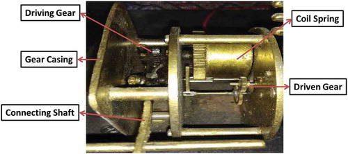
In , the gear pattern utilised in the fabrication process gives an output of 3000 rotation per minute (RPM) to the dynamo shaft. The system converts the linear vertical motion of spring compression to the angular motion of the driving gear. There are five gears which are installed there in the gearbox, followed by a coil spring to store the mechanical power. The fabricated gear pattern and coil spring arrangement is shown in .
Figure 1. Side, top and sectional view of gear arrangement in sketch diagram
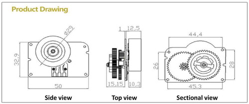
Figure 2. Top view of the fabricated gear pattern and coil spring placement
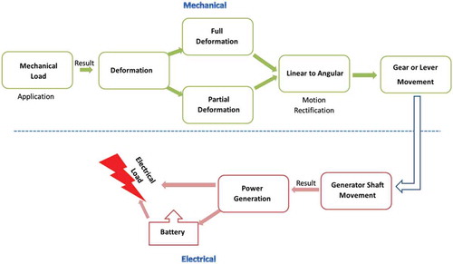
2.3. Mechanical rectification
The conversion of mechanical energy to electrical energy was utilised in the proposed system using gear and shaft arrangement. The loss during electromechanical conversion was minimised by storing maximum mechanical power in the coil spring. The hump of speed breaker design is the first part of the system that attains load; therefore, the material of the hump must be strong enough to bear the passing load. Acrylonitrile Butadiene Styrene (ABS) material was used here and well-validated by numerical simulations (details in section 3) before implemented in the system. ABS proposes excessive endure capability to tolerate dead load and higher resistance to severe impacts. Hump deflects axial spring that is made up of stainless steel to regain the initial position of hump after compression. The gear arrangement and generator plays an important role in the rectification of generated mechanical energy into electrical energy. shows the general mechanical rectification system.
Figure 3. General working principle of mechanical rectification
2.4. System working
As described in , after the vehicle passes over the bump, the spring placed under the bump gets compressed. The shaft connected to the bump performs an angular motion which is then converter to linear motion by the help of the flywheel. The flywheel shaft is connected to the driving gear, which rotates with the compression of spring. The driving gear is connected to coil spring which stores the torsion. After cut-off torsion of coil spring, it releases the stored mechanical energy and gives the rotation to the driven springs.
Figure 4. Schematics of implemented energy harvester which depicts complete system arrangement and process flow of the developed system
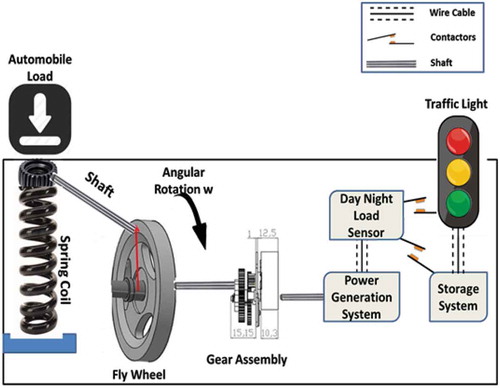
The driven springs yield an output of approximately 3000 RPM at the generator shaft. As the generator shaft rotates, it results in the power generation at the output terminal of the generator. The produced power is rectified and fed to either directly to the load or storage device depending upon the feedback of light detector. The fabricated model of energy harvester is shown in . shows the list of components used in the present system.
Figure 5. Prototype of energy harvester
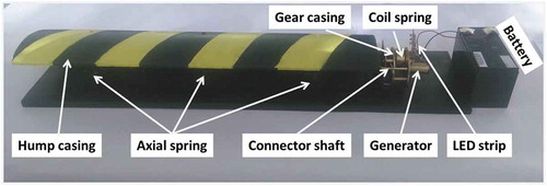
Table 2. Component wise description and their functions
3. Finite element modelling to validate material and its properties
In this part, a sectional part of the model has been simulated using Finite Element tool like ANSYS to predict parameters associated with deflection of breaker structure. Finite Element Modelling plays an important role here to predict the reliability and strength of speed breaker material proposed to use here. Speed breaker structure made up of ABS has been simulated using three different dead loads i.e. 100 Kg, 400 Kg and 800 Kg uniformly distributed over the entire structure. These three loads are considered to observe the behaviour of material via plotting load versus deflection curve and calculating maximum stress. Further, these calculations can be compared with standard mechanical properties of ABS material i.e. ultimate and yield tensile strength to forecast maximum load which we can apply on the structure. shows the dimensions of the computational model.
Figure 6. Dimension of model having plate area of 520 mm x 370 mm and hump of 100 mm
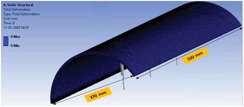
In , a hump of 100 mm has been created and three springs are placed in series to validate it with the real scenario. Plate area of 520 mm x 370 mm has been taken and area calculated via semi-cylindrical approach. Here we are taking the sectional length of 520 mm as we want to predict deflection and stress response only. shows maximum deflection depicted on applying 100 Kg (i.e. 980.67 N) of uniformly distributed load. Deflection of approximately 2.38 mm has been observed giving maximum stress produced by the structure as 0.0035 MPa.
Figure 7. Finite Element Modelling representing deflection contour having uniform distributed loading of 980.67 N
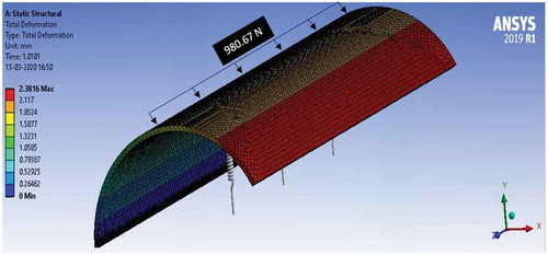
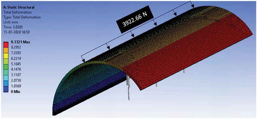
It can be estimated via simulation result that 100 Kg dead load or 980.67 N of the uniform-distributed load is giving very less deflection. Further, we can increase our loading capacity, so dead load of 400 Kg i.e. 3922.66 N of the uniform-distributed load is applied on the structure. Deflection of approximately 9.3321 mm has been observed giving maximum stress produced by the structure as 0.0142 MPa as shown in .
Figure 8. Finite Element Modelling representing deflection contour having uniform distributed loading of 3922.66 N
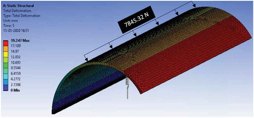
Final simulation is performed here assuming 800 Kg dead load or 7845.32 N of uniform distribution loading. This value is considered to check graphical curve behaviour of load v/s deflection as we are not cleared yet. Deflection of approximately 19.247 mm has been observed giving maximum stress produced by the structure as 0.0285 MPa as shown in .
Figure 9. Finite Element Modelling representing deflection contour having uniform distributed loading of 7845.32 N
These simulations are mainly performed to check proposed structure material reliability and stability. Comparing ABS mechanical properties with resulted stresses, we can consider ABS as a good option. It is efficient and economical as we compare it with other available options. shows some of the standard mechanical properties of ABS.
Table 3. Properties of Acrylonitrile Butadiene Styrene (ABS) (MatWeb)
Comparing the resulted stress values with some standard mechanical properties, it is estimated that ABS is a stable material choice. Further loading predictions can be estimated by plotting graphs between load, deflection and stress as shown in .
Figure 10. Load vs Deflection curve
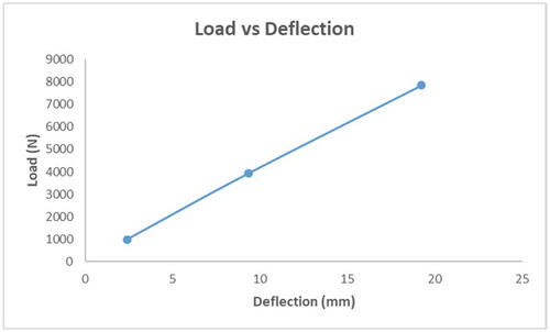
Figure 11. Stress vs Load curve
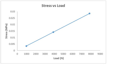
The computational model is considered having the sectional length as of realistic model. Validating mechanical properties of ABS, we can further arrange two similar models in series for estimating full-length behaviour. It can be predicted from that stress and deflection are having linear growth with respect to the applied load, so we can arrange this structure in multiple series for our desired result.
4. Results and discussion
The developed prototype was tested under laboratory conditions. The applied dead load was by manual compression. The various parameters obtained as a result of the testing module are listed in . The tested prototype was having a single unit.
Table 4. Values of various parameters obtained from the laboratory testing due to manual compression
The dimension of the real model is 1.040 m x 0.370 m x 0.10 m. The peak power output of the system is noted as 4.6 W. The steady-state output is 3.25 W. The minimum weight to counter full compression of the spring is 60 kg and it corresponds the maximum power generation. The marked output depicts the power generation on full compression and elongation. The weight lying between 0 to less than 60 kg will result in partial compression and elongation of the helical spring and corresponding rotation of gears. The followed mechanism stores power in the mechanical form in the coil spring. The dead load exceeding 60 kg will be encountered by the speed breaker hump. There are two load terminals connected to the output of the generator which is fulfiling the two different purposes of direct power supply to the load and storing the electrical energy in the battery, respectively. The spring which is installed under the road breaker is getting twice compression of 7 cm each time it is compressed. The coil spring results to vertical motion of connecting shaft for both compression and elongation. The spring constant is 6000 N/m. With each passing vehicle on the speed breaker, the system generates power which is designed to be fed to the storage unit or direct load depending upon the lightening condition. The generated power varies with vehicle movement on the speed breaker and the same is shown in .
Figure 12. Power Vs time for each sedan crossing over the speed breaker
On each compression, the device will produce 6.5 W output. The storage device that is used here is UPS battery having a voltage level of 12 V and current level of 7A.
Figure 13. Synchronous mechanism of alternator at various speeds including synchronous speed
From it can be depicted that the torque of the alternator is maximum at 3000 RPM. Increasing the speed above 3000 RPM does not change the output much. Thus, the saturation is achieved at 3000 RPM. If such a system is installed on the real speed breaker then there will be such four breaker system will be required to create a single lane road speed breaker. Every breaker system is equipped with two generating stations hence the net power output of the system will be 8*3.25 W = 26 W of steady state power. From a single lane single hump speed breaker. The series of humps will generate integral power output as that of the single breaker output. For a road having four humps and working on double lane road, the net power output will be 208 W. The generated power will be sufficient enough to power the street lights and traffic signals.
5. Conclusion
The presented energy harvesting system is compact, efficient, durable, and also eco-friendly harvester. The power generated was 3.25 W and 4.6 W for steady-state and peak state, respectively, of the energy harvester converting the deflection. The speed breaker structure material is well validated via computational modelling and linear cure obtained between stress, deflection and load graphs. On the movement of a sedan which crosses such two proposed systems twice on the road as the front and rear axle passes over, the peak power output observed was about 18 W. The obtained high power levels can be utilised for street lights, traffic lights, road diversion indicators and many more applications. The test results have shown a great prospect of new energy conversion idea in harvesting the vibration energy and obtaining an adequate power output.
Acknowledgements
Authors are grateful for the support received from Department of Science and Technology, Government of India (Project No: SP-YO-058-2017).
Disclosure statement
No potential conflict of interest was reported by the authors.
Additional information
Notes on contributors
Nikhil Raj
Mr. Nikhil Raj completed his B. Tech in Power System Engineering from the University of Petroleum and Energy Studies, Dehradun in 2017 and currently pursuing MBA in Power Management. He holds a professional experience of 3+ years in the field of solar PV project management and R&D in the field of electromagnetic wave trapping. He has a proven record of R&D since his bachelor's study and has 3 filed patents. Currently working as Project Associate in a DST funded project on wireless power transmission.
Ankit Dasgotra
Mr. Ankit Dasgotra obtained his Bachelors in Mechanical Engineering from Himachal Pradesh Technical University, Hamirpur and Masters in Mechanical Engineering (specification in thermal) from IIT Roorkee. He is having Industrial/Research experience of 3 years and now associated as Doctoral Research Fellow in University of Petroleum and Energy Studies (UPES). He is having several journal/conference publications and awarded scholarships from the government of India.
Surajit Mondal
Dr. Surajit Mondal obtained his Bachelors in Electrical Engineering from Asansol Engineering College and Masters in Energy Systems from UPES, Dehradun. He did his PhD in the area of Solar Thermal Applications on June 2020. He is having Research and teaching experience of 6 years and now associated as Assistant Professor at University of Petroleum and Energy Studies (UPES). He is having several journal/conference publications and awarded the Young Scientist award from the government of India and sanctioned a research grant of INR 33.67 Lakhs.
Suresh Kumar
Dr. Suresh Kumar is both academician and researcher with more than 24 years of professional experience having academic and administrative leadership skills. Handled successfully different roles like Head of Department, Associate Dean, Dean (Engineering), Dean (Academics) and Director. Achieved academic excellence at Institute/department level by developing industry based curriculum, implementing OBE, improving teaching-learning process, conceptualizing student leadership, building industry partners for curriculum delivery, project based learning, faculty development, attracting external research grants and building alumni network. Published research articles having TIF 80 in reputed journals published by Elsevier, Taylor & Francis and Springer, and in proceedings of ASME/ISES conferences. Fetched research grant worth INR 42 Lakhs from DST. Experienced in operation and maintenance of high pressure steam boilers, turbines, sugar mills, pumps. Chaired Board of Studies of UPES Dehradun and Uttarakhand Technical University.
Ravi Kumar Patel
Dr. Ravi Kumar Patel completed his Doctorate in the areas of 3D printing, materials engineering, and water treatment from the University of Petroleum and Energy Studies, Dehradun, India. He has also worked in the domain of robotics and automation during his masters (M. Tech). He visited the University of Poitiers and the University of Rennes in France as a research trainee under the scholarship received by the Indo-French Centre for the Promotion of Advanced Research (IFCPAR). In total, he has published/communicated around 11+ research/review articles in the international journals, filed 04 patents under the Indian Patent Act, and received 02 UPES-SEED funded projects. He has also worked for various projects funded by the Department of Science and Technology, Govt. of India.
References
- Bocchio, J., V. Wittemberg, and J. Quagliano. 2017. “Synthesis and Characterization of Polyurethane/bentonite Nanoclay Based Nanocomposites Using Different Diisocyanates: Relation between Mechanical and Thermal Properties.” 3rd. International Conference on Structural Nanocomposites (Nanostruc 2016), United Kingdom - Aberdeen, IOP Publishing.
- Chiarelli, A., A. Al-Mohammedawi, A. Dawson, and A. Garcia. 2017. “Construction and Configuration of Convection-powered Asphalt Solar Collectors for the Reduction of Urban Temperatures.” International Journal of Thermal Sciences 112: 242–251. doi:https://doi.org/10.1016/j.ijthermalsci.2016.10.012.
- Churchill, E., and J. Noble. 1971. “A Demonstration of Lenz’law?” American Journal of Physics 39 (3): 285–287. doi:https://doi.org/10.1119/1.1986123.
- Cui, J., H. Yoon, and B. D. Youn. 2018. “An Omnidirectional Biomechanical Energy Harvesting (Obeh) Sidewalk Block for a Self-generative Power Grid in a Smart City.” International Journal of Precision Engineering and Manufacturing-Green Technology 5 (4): 507–517.
- Dawson, A., R. Mallick, A. G. Hernandez, and P. K. Dehdezi. 2014. “Energy Harvesting from Pavements.” In Climate Change, Energy, Sustainability and Pavements, edited by Kasthurirangan G., W. JvdM Steyn, and J. Harvey, 481–517. Springer.
- Delhom, C., L. White-Ghoorahoo, and S. Pang. 2010. “Development and Characterization of Cellulose/clay Nanocomposites.” Composites Part B: Engineering 41 (6): 475–481. doi:https://doi.org/10.1016/j.compositesb.2009.10.007.
- Ding, G., X. Zhao, F. Sun, and J. Wang. 2018. “Effect of Subgrade on Piezoelectric Energy Harvesting under Traffic Loads.” International Journal of Pavement Engineering 19 (no 8): 661–674. doi:https://doi.org/10.1080/10298436.2017.1413241.
- Firestone, F. A. 1933. “A New Analogy between Mechanical and Electrical Systems.” The Journal of the Acoustical Society of America 4 (3): 249–267. doi:https://doi.org/10.1121/1.1915605.
- Gao, Q., Y. Huang, M. Li, Y. Liu, and Y. Yan. 2010. “Experimental Study of Slab Solar Collection on the Hydronic System of Road.” Solar Energy 84 (12): 2096–2102. doi:https://doi.org/10.1016/j.solener.2010.09.008.
- Gholikhani, M., M. Sharzehee, S. A. Tahami, F. Martinez, S. Dessouky, and L. F. Walubita. 2019. “Effect of Electromagnetic Energy Harvesting Technology on Safety and Low Power Generation in Sustainable Transportation: A Feasibility Study.” International Journal of Sustainable Engineering 13(5): 1–14.
- Kaushik, A. 2018. “Analysis of At&c Loss Reduction Techniques in 11 Kv Electrical Distribution System (Bses Yamuna Power Ltd., Delhi).” Indian Journal Of Applied Research 7 (5): 46–49.
- Kim, J. E., H. Kim, H. Yoon, Y. Y. Kim, and B. D. Youn. 2015. “An Energy Conversion Model for Cantilevered Piezoelectric Vibration Energy Harvesters Using Only Measurable Parameters.” International Journal of Precision Engineering and Manufacturing-Green Technology 2 (1): 51–57. doi:https://doi.org/10.1007/s40684-015-0007-x.
- Lee, S., Y. Lee, D. Kim, Y. Yang, L. Lin, Z.-H. Lin, W. Hwang, and Z. L. Wang. 2013. “Triboelectric Nanogenerator for Harvesting Pendulum Oscillation Energy.” Nano Energy 2 (6): 1113–1120. doi:https://doi.org/10.1016/j.nanoen.2013.08.007.
- Li, Z., Z. Yan, J. Luo, and Z. Yang. 2019. “Performance Comparison of Electromagnetic Energy Harvesters Based on Magnet Arrays of Alternating Polarity and Configuration.” Energy Conversion and Management 179: 132–140. doi:https://doi.org/10.1016/j.enconman.2018.10.060.
- Liu, M., R. Lin, S. Zhou, Y. Yu, A. Ishida, M. Mcgrath, B. Kennedy, M. Hajj, and L. Zuo. 2018. “Design, Simulation and Experiment of a Novel High Efficiency Energy Harvesting Paver.” Applied Energy 212: 966–975. doi:https://doi.org/10.1016/j.apenergy.2017.12.123.
- Matweb. “Material Property Data.” http://www.matweb.com/search/DataSheet.aspx?MatGUID=3a8afcddac864d4b8f58d40570d2e5aa&ckck=1.
- Mukhopadhyay, A., D. N. Basu, S. Mondal, and S. Sen. 2020. “Dynamic Behaviour, Identification and Control of Energy Systems.” In Dynamics and Control of Energy Systems, edited by Achintya M., S. Sen, D. Narayan Basu, and S. Mondal, 3–7. Springer.
- National Rural Roads Development Agency and Ministry of Rural Development, GOI. 2017. New Delhi: Govt of India.
- Nigam, V., D. Setua, G. Mathur, and K. K. Kar. 2004. “Epoxy‐montmorillonite Clay Nanocomposites: Synthesis and Characterization.” Journal of Applied Polymer Science 93 (5): 2201–2210. doi:https://doi.org/10.1002/app.20736.
- Park, H., and J. Kim. 2016. “Electromagnetic Induction Energy Harvester for High-speed Railroad Applications.” International Journal of Precision Engineering and Manufacturing-Green Technology 3 (no 1): 41–48. doi:https://doi.org/10.1007/s40684-016-0006-6.
- Park, J.-H., T.-W. Lim, S.-D. Kim, and S.-H. Park. 2016. “Design and Experimental Verification of Flexible Plate-type Piezoelectric Vibrator for Energy Harvesting System.” International Journal of Precision Engineering and Manufacturing-Green Technology 3 (3): 253–259. doi:https://doi.org/10.1007/s40684-016-0033-3.
- Pei, J., B. Zhou, and L. Lyu. 2019. “E-road: The Largest Energy Supply of the Future?” Applied Energy 241: 174–183. doi:https://doi.org/10.1016/j.apenergy.2019.03.033.
- Salman, W., L. Qi, X. Zhu, H. Pan, X. Zhang, S. Bano, Z. Zhang, and Y. Yuan. 2018. “A High-efficiency Energy Regenerative Shock Absorber Using Helical Gears for Powering Low-wattage Electrical Device of Electric Vehicles.” Energy 159: 361–372. doi:https://doi.org/10.1016/j.energy.2018.06.152.
- Santhosh, M., B. S. Kumar, and T. Yuvaraja. 2017. Energy Harvesting Using Speed Breaker Mechanism. In 2017 International Conference on Electrical, Electronics, Communication, Computer, and Optimization Techniques (ICEECCOT), 201–204. Mysuru: IEEE.
- Schwanitz, V. J., F. Piontek, C. Bertram, and G. Luderer. 2014. “Long-term Climate Policy Implications of Phasing Out Fossil Fuel Subsidies.” Energy Policy 67: 882–894. doi:https://doi.org/10.1016/j.enpol.2013.12.015.
- Thein, C. K., F. M. Foong, and Y.-C. Shu. 2018. “Damping Ratio and Power Output Prediction of an Electromagnetic Energy Harvester Designed through Finite Element Analysis.” Sensors and Actuators A: Physical 286: 220–231.
- Toh, C. K., J. A. Sanguesa, J. C. Cano, and F. J. Martinez. 2020. “Advances in Smart Roads for Future Smart Cities.” Proceedings of the Royal Society A 476 (2233): 20190439. doi:https://doi.org/10.1098/rspa.2019.0439.
- Xiang, B., X. Cao, Y. Yuan, L. Sun, H. Wu, and F. Haghighat. 2018. “A Novel Hybrid Energy System Combined with Solar-road and Soil-regenerator: Dynamic Model and Operational Performance.” Energy Conversion and Management 156: 376–387. doi:https://doi.org/10.1016/j.enconman.2017.11.066.
- Yang, C. H., Y. Song, M. S. Woo, J. H. Eom, G. J. Song, J. H. Kim, J. Kim, T. H. Lee, J. Y. Choi, and T. H. Sung. 2017. “Feasibility Study of Impact-based Piezoelectric Road Energy Harvester for Wireless Sensor Networks in Smart Highways.” Sensors and Actuators A: Physical 261: 317–324. doi:https://doi.org/10.1016/j.sna.2017.04.025.