
 ?Mathematical formulae have been encoded as MathML and are displayed in this HTML version using MathJax in order to improve their display. Uncheck the box to turn MathJax off. This feature requires Javascript. Click on a formula to zoom.
ABSTRACT
The effect of Aspect ration on melting process of PCM (polyethylene glycol 1500 (PEG 1500)) in a rectangular encloser was investigated using CFD modelling. The CFD model was validated by experimental measurement performed for one case of aspect ratio of 2.31 with height = 155 mm, width = 67 and depth = 200 mm. The study was conducted in two phases: i) constant height enclosure, ii) constant volume enclosure. The main conclusions from this study are: i) the conduction heat transfer is the only mode of heat transfer in the first 250 secs from the start of heating of PCM. Then, the evolution of natural circulation starts at the hot wall and developed to a complete steady cycle after 2000 secs. ii) the results indicate a clear effect of the aspect ratio (AR) on melting percentage with peak at AR = 2,31 for both cases of constant heght and constant volume. iii) the results also show that there is a limiting width of the encloser where the circulation velocity reduced to low values (<0.3 mm/s) regardless of the enclosure heht.
| Nomenclature | = | |
| Cp | = | specific heat (J/kg K) |
| H | = | specific enthalpy (J/kg) |
| ΔH | = | modified latent heat (J/kg) |
| T | = | Temperature (K) |
| Ti | = | initial temperature (K) |
| Tm | = | melting temperature (K) |
| Tsol | = | solidus temperature (K) |
| Tlid | = | liquidus temperature (K) |
| t | = | time (s) |
| k | = | thermal conductivity (W/m K) |
| V | = | velocity (m/s) |
| ∆Tp | = | the temperature difference between phases, |
| Greek letters | = | |
| µ | = | dynamic viscosity (kg/ms) |
| β | = | liquid fraction, dimensionless |
| ρ | = | density (kg/m3) |
| Abbreviations | = | |
| PCMs | = | Phase change materials |
| TES | = | Thermal energy storage |
| LHTES | = | Latent heat thermal energy storage |
| PEG | = | Polyethylene glycol |
| AR | = | Aspect Ratio |
1. Introduction
Energy demand around the world is rising and continually increasing energy production to meet this demand is not sustainable. Use of traditional fossil fuels to supply this energy demand will accelerate the detrimental effects such as global warming and pollution on the environment whilst depleting these reserves at an increasing rate. Production of energy using renewables can offset some of the increase in demand without the detrimental effects associated with fossil fuels but will have its own negative effects. Therefore, it is necessary to address the energy shortage by making a more efficient use of the useable energy already being produced. Thermal energy storage (TES) can effectively be used to deal with this energy shortage by minimising the energy requirement.
The use of TES systems is an emerging technology for thermal management where the system stores energy as sensible heat, latent heat and thermochemical processes or a combination of all three. Sensible heat storage systems store heat through the material’s heat capacity over a large temperature difference while latent heat storage systems incorporate material’s phase changes in addition to the heat capacity, to store thermal energy [2].
Latent heat thermal energy storage (LHTES) by phase change materials (PCMs) is a popular option due to their high energy density and their capacity to store energy at a constant temperature (or over a limited range of temperatures), at the temperature that corresponds to the phase transition temperature of the material (Al-Abidi et al. (Citation2013)). This makes latent heat storage more attractive.
One area of interest for this type of energy storage is for insulation and temperature control of subsea oil transmission pipelines, where the task is to prevent heat loss and maintain a stable temperature for a long time. It therefore has different requirements of a PCM than most latent heat thermal energy storage applications. In this case, a slow heat transfer rate is beneficial. Polyethylene glycol 1500 (PEG 1500) has been considered as a potential material for this application due to its desirable characteristics such as appropriate melting temperature and low thermal conductivity (Hamad et al. (Citation2017)).
What is now needed is an understanding of the melting characteristics of PEG1500 under a fixed applied temperature difference. Here are a number of papers published on classification of phase change materials, the melting/solidification in various geometries and the heat transfer mechanisms. The published papers related to melting/solidification in rectangular enclosures can be classified in two categories:
i) Category 1: The rectangular enclosures is heated from one side and insulated from all others sides. This gives a case where the applied temperature difference is changing with time as the PCM heats up, which reduces the driving force for heat transfer with time. The temperature difference will reach zero when the PCM has melted completely and its temperature is the same as the hot plate temperature. A summary of some experimental and numerical/simulation work published in the literature is given below.
Ho and Viskanta (Citation2017) studied experimentally and numerically the basic heat transfer behaviour during melting of n-octadecane from a constant temperature vertical wall of a rectangular cavity with AR = 2.6 (height = 130 mm, width = 50 mm). A numerical simulation of the corresponding two-dimensional melting process was performed, and the numerical prediction was compared with the experimental data. One of the main findings was the effect of the density-induced motion becomes more significant as indicated by the greater discrepancy between the measured and predicted melting front position.
Zhang et al. (Citation1993) study experimentally the possibility of using melting process of n-octadecane (C18H38) in a rectangular enclosure with AR = 1.5 (height = 90 mm, width = 60 mm) for periodic cooling of electronic components. Their results indicated that natural convection has a significant effect on the shape of the solid–liquid interface that becomes more pronounced as temperature difference increases.
Pal and Joshi (Citation2001) studied the melting of an organic phase change material, that is, n-triacontane (C30H62) in a tall enclosure with an aspect ratio of 10 (height = 130, width 13 mm). They found that natural convection played a dominant role during the final stage of melting.
Faraji and El Qarnia (Citation2010) studied numerically the melting of n-eicosane (C20H42) in a rectangular enclosure with AR = 1.5 (height = 90 mm, width = 60 cm) heated with three protruding heat sources with a constant and uniform volumetric heat generation equal to that generated within the actual Pentium microprocessor (CPU) Centrino Duo 4 (2.8 GHz). The results indicated that conduction was predominant at the bottom part of the PCM at early stage of the melting process. During the second stage, natural convection developed and the streamlines became relatively packed next to the active wall and the melting front, which leads to a relatively fast-moving flow next to those boundaries. The third stage started when the location of the intersection of the melting front and non-active vertical wall moved downward. Consequently, the heat flux transmitted to the liquid–solid interface decreased with time, which explains the decay of the rate of change in the liquid fraction.
El Qarnia, Draoui, and Lakhal (Citation2013) examine the impact of several key parameters of the PCM-based heat sink on its cooling capacity. They found that decreasing the aspect ratio from their reference values would result in a rise in the wall surface temperature of the heaters, reduction in operating time, and therefore, a decrease in the melted liquid fraction.
Joulin et al (Citation2011) studied the effect of Aspect ratio of rectangular thermal storage enclosure on natural convection numerically. The rectangular enclose heated from one side and all other walls are assumed adiabatic. They suggested the use of convective enhancement factor which is the ratio of convective heat flux to conductive heat flux for the same melt fraction. They found that increasing the height of the enclosure at constant width will reduce the heat transfer. However, increasing the width for constant height will enhance the heat transfer by convection. They also noticed that, for very small width (5 mm), the heat transfer take place only by conduction.
Behbahan et al. (Citation2019) studied the influence of aspect ratio and metal foam porosity on thermal performance of metal foam/PCM composite are investigated numerically.
The enclosure for all the cases has a constant volume with various aspect ratios. The left side of the enclosure is exposed to a thermal source having a constant heat flux, while the other three surfaces are kept thermally insulated. The results indicated that for higher porosities, enclosures with bigger aspect ratios proved to lead to optimal melting time. There results showed that the best enclosure aspect ratio and foam porosity to give the shortest melting time are 2.1 and 91.66%, respectively.
ii) Category 2: The rectangular enclosure heated from one side and the opposite side is kept at a constant temperature (heat source and sink) and adiabatic conditions on other walls. In this case heat transfer take place simultaneously from both the hot and cold plates. Due to the fixed temperature difference, the heat transfer will reach steady state when the heat added to the system is equal to heat loss from the cold side. A summary of the some experimental and numerical/simulation work published are given below.
Gadgil and Gobin (Citation1984) simulated numerically two-dimensional melting of a solid phase change material in a rectangular enclosure heated from one side. They found that the shape of the melting front is sensitive to the variation of the local heat transfer rate to the solid and is used as a test for the numerical simulation procedure. The results show that the aspect ratio (AR) has a strong influence on the melting curve. For example, an increase in AR from 1.13 to 5.25 reduces the time required to melt 80% of the PCM more than sixteen times.
Gau and Viskanta (Citation1986) and studied the effect of free convection on the shape and motion of the melting front of gallium in a rectangular test cell with AR = 1.4 (height = 88.9 mm, width = 63.5 mm, depth = 38.1). At very early times, before the buoyancy-driven flow was initiated, the interface shape was flat and parallel to the heated wall of the test cell. Heat transfer was dominated by conduction. As the heating progressed the buoyancy-driven convection in the melting zone started to develop and continued to intensify. This is evidenced by the appearance of a non-uniform melt layer receding from the top to the bottom of the test cell. They reported that for larger aspect ratio, melting of the solid near the top may be greatly promoted, and melting near the bottom of the test cell may be completely terminated, due to free convection in the melting zone.
Mbaye and Bilgen (Citation2005) carried out a more recent study on gallium, in a rectangular enclosure subjected to a constant heat flux on its left vertical wall and a constant temperature on its right wall. The enthalpy formulation with the finite difference-control volume method found that the heat transfer and melting velocity were controlled by heat flux and further that the heat transfer attained a maximum value at an aspect ratio of about one.
Wang, Amiri, and Vafai (Citation1999) studied the thermal characteristics of the melting process of PEG 900 in a rectangular enclosure of AR = 0.67 (height = 103 mm, width = 153 mm) heated from a vertical side. The temperature distributions in the PCM along the top wall, mid-plane and the bottom wall were presented. The increase in hot wall temperature enhanced the convection heat transfer and more solid PCM melted over the same time period. It was shown that the temporal variation of the Nusselt number distinguishes three different heat transfer regimes during the melting process (conduction-dominated regime, a transition regime, and convection-dominated regime). A similar conclusion was found by Shokouhmand and Kamkari (Citation2013) on evolution of heat transfer with time in their investigation of melting heat transfer characteristics of lauric acid in a rectangular enclosure.
Joulin et al. (Citation2011) studied the energy storage and the energy recovery by comparison of experimental data and numerical modelling for AR = 5.6 (height = 140, width = 25, depth = 210). A hydrated salts, mineral, containing potassium and calcium chlorides was used as PCM. A 1-D finite difference method (FDM) incorporated in an in-house FORTRAN code as well as 2-D CFD model using FLUENT were applied for the computation of the thermal behaviour of the PCM. Predictions based on both methods exhibited a very good agreement with the experimental observations for the melting process with a deviation of less than 5%.
Bouteldja, Mezaache, and Aouer (Citation2019) investigated the influence of the aspect ratio and Grashof number on the convection diffusion phenomena during PCM solidification within a rectangular cavity. Water was used as phase change material, for an aspect ratio range 0.5 to 4. The left and right walls of the cavity were maintained at constant hot and cold temperatures, respectively, while the upper and lower surfaces are considered adiabatic. The results showed that the solidification phase change process depends considerably on the thermal and geometrical parameters of the system.
Müslüm, Tütüncü, and Campo (Citation2018) investigated the melting of paraffin wax dispersed with CuO nanoparticles inside a square enclosure numerically using the enthalpy-porosity technique. A cosinesoidally varying temperature was imposed on a hot wall, while the facing cold wall was kept at a constant temperature. The effect of volume fraction of nanoparticles in conjunction with the orientation of the heated wall (heating from a side wall or heating from the bottom) on the melting process were examined. Calculations demonstrated that the melting rate and the stored energy for the case of heating from below is considerably higher than the case of heating from the side. With the dispersion of nanoparticles in the paraffin wax, the melting rate and the stored energy are increased significantly. A higher enlargement is attained for the nanoparticle volume fraction of 1% as compared to that of 3 vol%.
The above review indicates that a number of papers have been published on melting processes of different aspect ratios for thermal storage applications. Most of these publication aims to enhance heat transfer process using various methods such as fins, metal foam and nanofluid. However, there is a lack of a comprehensive study on the effects of aspect ratio on melting processes for the applications of heating from one side while there is heat loss from the opposite side of the enclosure.
The main aim of present work is to study in detail the effect of aspect ratio on melting process in a rectangular enclosure heated from one side while cooled from the other side. The polyethylene glycol 1500 (PEG 1500) is used in this research as it is suitable for energy storage-insulation application for oil pipelines. Two geometrical cases are studied in this paper: A) The heating wall area was held constant and the width of the enclosure changed to give the desired change in aspect ratio; B) The volume of the enclosure was held constant and the aspect ratio changed by varying the height and width (keeping depth constant). To achieve the main aim of this study, the following objectives are considered: i) Development of a CFD model with the dimensions of (155 mm x 67 m x 200 m) to mimic the experiment rectangular enclose used by Hamad et al. (Citation2017) which is used to validate the model, ii) To produce melting contours to visualise the evolution of the melting process data for aspect ratios in the range of 0.5 to 20, iii) The model was used to produce profiles for the natural circulation velocity at different times to understand the transition of heat transfer from conduction to convection.
2. Methodology
2.1 The computational domain
The computational domain (see in a) is that of a simple modelled system. The rectangular enclosure is represented by the two-dimensional (2D) computational domain that is bounded by the hot and cold walls. This enclosure is filled with PEG 1500. The model is simulated over set periods of time, namely: 100, 500, 1000, 2500, 5000, 7500, 10,000, 12,500, 15,000, 17,500, 20,000 and 22,500 secs. This is done to give snapshots of how the melt front moves with time for the given temperature difference.
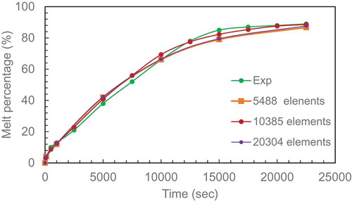
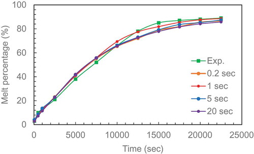
Figure 1 (a) Computational domain of the rectangular enclosure. (b) Grid independence study. Experimental data from .Hamad et al. (Citation2017). (c) Time step independence study. Experimental data from .Hamad et al. (Citation2017)
Two scenarios were considered. Scenario 1 involved keeping the height and depth constant hence the area available for heat transfer is constant. Only the distance between the hot and cold plates (width) is varied to give the desired aspect ratios (AR = 0.5, 1.0, 2.31, 3.875, 5.17, 7.75, 15.9 and 20).
Scenario 2 involved keeping the volume of the PCM constant and hence the mass of PCM, or energy storage capacity constant. This was achieved by keeping the depth constant and changing the height and width simultaneously.
2.2 Governing equations
The continuity Equation (Fluent, Citation2020):
The melting process is solved using the enthalpy-porosity method. The energy equations is given as (ANSYS Fluent user guide (Citation2020):
where is the density (kg/m3);
is the fluid velocity, (m/s); S is the volumetric heat source term (set to zero in the present work), in J/m3; H is the enthalpy of the PEG 1500 (J/kg); K stands for the thermal conductivity (W/mK); and T is the temperature (K).
The total enthalpy (H) of a system, is computed as the sum of the sensible enthalpy (h) and the latent specific enthalpy (∆H) at any point as:
where h, the sensible enthalpy at a point and at a given instant of time is represented as:
and href (J/kg) is the reference enthalpy at the reference temperature Tref, (K). Cp is the specific heat at constant pressure (J/kg); and ∆H is the latent heat content that may change between the solid state and the liquid state (J/kg).
The content of the latent heat can vary between zero (when the material is solid, β = 0) and L (when the material is liquid, β = 1). The liquid fraction (β) which occurs during the phase change between the solid state and the liquid state is calculated as:
β is the liquid fraction and L is the Latent heat and;
represent the solidus and liquidus temperature. Solidus is the maximum temperature at which the material is at solid state and liquidus is the minimum temperature at which the material is at liquid state.
The momentum Equation is given as:
The following assumptions are made to simplify the problem:
Melting process is transient.
The specific heat capacity, viscosity and thermal conductivity of the PCM vary as piecewise linear.
PEG 1500 is pure and when in its liquid phase, it is incompressible
Thermal radiation and viscous dissipation are negligible
There is no heat generation within the PCM
Buoyancy is considered in the momentum equations through the Boussinesq approximation.
As the temperature increases, the density decreases (ρ ~ 1/T) and thus the low-density PEG rises to the top and the high-density PEG sinks to the bottom of the container. Therefore, natural convection was taken into account by firstly including the gravity term in the Y-direction and then using the Boussinesq approximation as the gravity force term with an operating temperature equal to the solidification/melting temperature.
The Boussinesq approximation was given by:
Where α is the thermal expansion, taken as 0.001 to be assumed negligible (Goyal et al. Citation2013)
2.3 Solution set up
The transient melting/solidification model was chosen for all cases. The material properties such as specific heat capacity, thermal conductivity and viscosity were included and considered as functions of temperature. The boundary conditions were set at 353 K for the hot side and 292 K for the opposite cold side. The rest of the sides were modelled as being adiabatic by setting the heat flux at the wall equal to zero.
The simulations were performed using the pressure-based model which is suitable for the melting and solidification model in ANSYS Fluent user guide (Citation2020)]. Based on the series of schemes used in PCM applications, a QUICK spatial discretisation scheme is used to solve the momentum and energy equations; the PRESTO scheme is selected for the pressure correction equation; and the semi-implicit method for pressure-linked equations (SIMPLE) algorithm is used for the pressure-velocity coupling. Convergence is obtained with the residuals of the continuity, energy and momentum equation set to be 10−5. The solidification/melting model with a constant of 106 is applied in order to model the mushy zone.
The thermos-physical properties of PEG 1500 are detailed in the . (Sundararajan, Samui, and Kulkarni Citation2017)
2.4 Mesh generation
A simple two-dimensional model is used because experimental observation confirmed that no significant temperature variation occurs in the depth direction. Meshing and solving of the 2D model is carried out using ANSYS Fluent. To ensure independence of solution, different time step values using the same grid size and different grid sizes using the same time step value, have been studied.
A mesh independent study was performed with a coarse mesh and solved before repeating with finer meshes to check the change in melting percentage with time. The data from the three cases of 5488, 10,385, 20,304 elements and experimental data (hamad[4] for aspect ratio 2.31 are plotted in . The results show that 10,385 elements can be used with a recallable accuracy. This number of mesh can now be used as a reference point to calculate the mesh for other ARs based on area ratio between them and the AR = 2.31.
The effect of time step was also checked by running four cases for 0.2, 1, 5 and 20 second and comparing with experimental data 9Hamad et al. (Citation2017)
(Hamad et al. (Citation2017)) in . The results show that a 1 second time step produces reasonable agreement with the experimental data. This time step was applied for all the aspect ratios used in this study.
3. Results and discussion
This section presents the detailed analysis of the evolution of the solid–liquid interface, melt fraction, effect of AR on melting percentage, natural circulation, heat balance of the melting process. The results of the simulation were recorded at regular intervals (100, 500, 1000, 2500, 5000, 7500, 10,000, 12,500, 15,000, 17,500, 20,000 and 22,500 secs) for a melting cycle of 22,500 secs (375 minutes).
3.1 Interaction of heat transfer, melting progress and natural circulation
shows a sample of melting and velocity contours at the early stage and the end of the experimental time used in this study. The heat transfer graph is also added to this Figure to show the interaction between the three variables. The melting process is initiated by starting the flow of hot water which raises the hot plate temperature to steady state at 80°C. The PCM begins to melt and the three variables are recorded at specific times when a significant change is observed.
Figure 2 (a) Melting contour and velocity contour at 500 and 22,500 se. The graph for heat transfer is added to this Figure to complete the picture of the interaction between the three variables. (b) Evolution of the natural circulation velocity distribution with time at three lines plotted at 10 mm from the bottom (LL), 10 mm from the top (UL) and mid-height (ML) of the PCM rectangular enclosure (constant height case,155 x 67, AR = 2.31). (c) Variation of maximum velocity with time at three lines plotted. (d) Variation of temperature difference and maximum velocity with time for melted PCM in enclose (AR = 2.31)
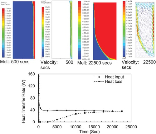
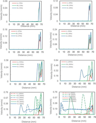
Figure 2 Continued
Figure 2 Continued
From the heat transfer graphs in , we can observe: i) The heat input reduces steeply in the first 500 secs due to the high temperature gradient between the hot plate and the PCM and then becomes almost constant for the rest of the time, ii) The heat loss from cold wall increased gradually with time until it matches the heat input from hot wall at around 20,000 s. The heat transfer reached steady state conditions and no more PCM melted.
The increase in heat losses can be explained as follows: As the melting process evolves, the temperature of the box walls and PCM surface start increasing with time. The increase in temperature is very slow in the early stages of the melting process as most of the heat is used to melt the PCM at its melting temperature. After a certain time, the melting rate starts to decrease due the increase in overall temperature of the PCM box which reduces the heat input from the hot wall given the local temperature gradient has decreased . a second factor is that more of the heat is lost from the other walls and PCM surface due to the increased temperature gradients between these points and the surroundings. This is leading to a steady state condition where the melting rate approaches zero and the heat input equals the heat losses.
From the melting contours in , it can be observed that melting started with a homogeneous thin layer adjacent to the heated wall and completed with concave liquid-solid interface. Initially, the layer is very thin and the viscous drag forces are too high to be overcome by buoyancy effects induced in the liquid layer due to the temperature difference and heat transfer is governed by conduction. As the layer becomes thicker than the viscous drag from the walls are reduced. The buoyancy effect is now able to create instability in the liquid layer and this non-equilibrium state generates movement of the liquid to the top of the enclosure at the early stage of melting as shown in (125 s case).
The development of the natural circulation is investigated in more detail by tracking velocities three levels, that is, the bottom, middle and top of the enclosure to record and plot the velocity distribution. shows the velocity distribution in the liquid zone within the enclosure at the three locations (LL: lower line, Ml: middle line an UL: upper line) at 10 different times.
The first set of data was collected at 125 s. A peak is seen very close to the hot wall indicating the onset of liquid motion upward close to the hot wall. This is an indication of the start of the formation of the boundary layer. The velocity distribution from the three locations are very similar and have same values with a maximum value of 0.055 mm/s.
For time = 250 secs, the three velocity distributions are very similar and have same values but two maxima and one minimum between them are visible. The maximum value is increased to 0.092 mm/s. The appearance of the two maxima is an indication of the completed circulation of the fluid the first peak within the boundary layer (at 66 mm from the cold wall) indicates upward flow due to the buoyancy effect as the PCM is heated and density drops. The second one at the liquid-solid interface (64 mm from cold face) indicates flow downward due to increased density of the PCM as it cools as heat is lost to the solid. A reduction in flow is indicated by the trough between the two peaks suggesting the horizontal flow across the chamber is slower than the two vertical flows given it is an induced flow between the hot and melt interface This on set of circulation motion coincides with the additional contribution to heat transfer by convection in heat transfer process.
The natural circulation contribution increased with elapsed time as the maximum velocity increased to a maximum after 2500 secs. The increase in the gap between the two maximums is proportional to the distance between the hot plate and the solid–liquid interface. The maximum velocities from each line are plotted with the time in . The graphs show that velocity increased and becomes almost constant after 2000 seconds. It can also be observed from data produced from the model prediction that the velocity of the middle line is almost twice that of the upper and lower lines. The highest velocity of the middle line may be attributed to the transition from one-dimensional flow at mid-height of the enclosure compared to two-dimensional flow near the top and bottom of the enclosure when the flow change it direction and the area for flow increased (continuity equation). This velocity gradient may be attributed to the maximum difference in temperature (density) between the middle line and both upper and lower lines which affect the buoyancy force. Accordingly, the flow is accelerated from the lower line to the middle line as the temperature difference/buoyancy force increases
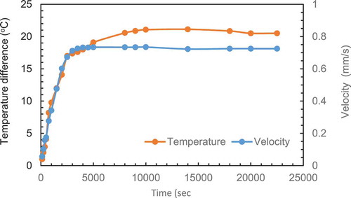
As described the natural circulation is generated by the density difference (buoyancy force) induced by the temperature difference between the top and bottom of the PCM box. The temperature difference between the top and bottom of the enclosure is recorded simultaneously with the velocity distribution.
The liquid zone was examined carefully for all the cases to select the appropriate location to record the temperature within the boundary layer. A distance of 3 mm from the heated plate was chosen. This distance was selected based on observation of the experimental cell as the median of the observed stagnant zone adjacent to the wall. The explanation of the choice of this location will follow in section. presents the evolution temperature difference and maximum velocity with time. The results show a clear correlation between the two variables.
3.1.1 Comparing CFD with the experimental studies
An initial experimental investigation as published by Hamad et al. (Citation2017) has been used to validate the prediction from CFD model. shows the position of the melt front predicted by simulation. The blue colour represents the condition at which the material is completely solid (β = 0) while the red colour represents the condition at which the material is completely liquid (β = 1). The overall liquid fraction domain is represented by the area weighted averages of liquid fraction for all cells. The mushy zone which represents the melt front interface separates the liquid region from the solid region. presents the corresponding position of the melt front at the same time of the experimental results in photographic form. gives a direct comparison of the melt front movement with time between the simulation and experimental results. A good agreement can be observed between the predicted evolution of melt front from simulation and the photos from experiments (Hamad et al. (Citation2017)). Deviation between the two data sets is less than 5% with the CFD consistently predicting a slightly faster melt rate. Overall, the discrepancy of 5% is small and within measurement accuracy hence the model can be used with high confidence in the predicting the data.
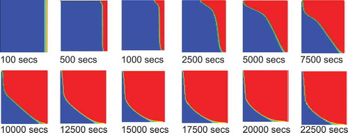
Figure 3 (a) The melt fraction contours for CFD set up for AR of 2.31. (b) The melt fraction contours of the experimental set up for AR of 2.31. (c) Overlay of CFD (dotted lines) and experimental (blocked lines) results. (d) Comparison of present data with previous work
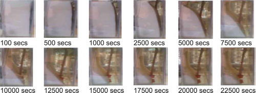
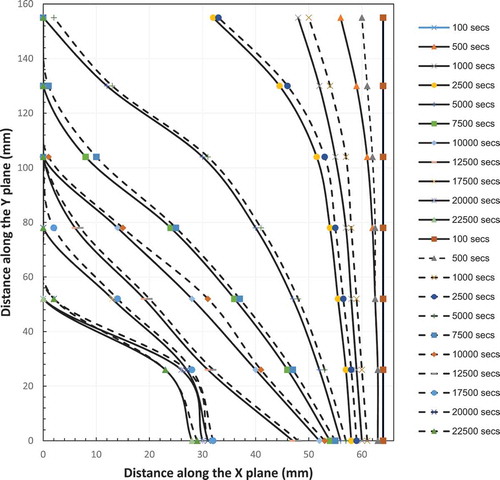
Figure 3 Continued
3.1.2 Comparing present data with previous work from literature
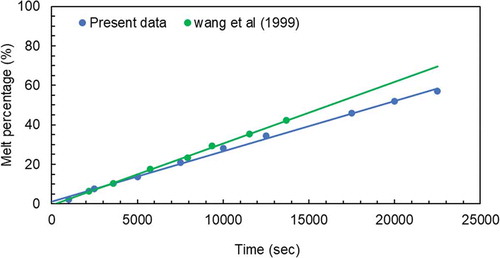
To the best of the authors’ knowledge, there is no extant data on this melting process for PEG 1500 in an open rectangular container. The nearest match of extant data was published by Wang, Amiri, and Vafai (Citation1999) for Peg 900. shows the melting percentage for the test cell used by Wang, Amiri, and Vafai (Citation1999) and the present work. The results show a linear trend of an increase in melting percentage for the aspect ratio around 0.7 but there is a difference in values. The difference in values may be attributed to the different latent heats of the PCM used and the difference in hot wall temperatures. A summary of these parameters is given below:
The enclosure of a rectangular cross-section with inside dimensions of 153 mm in width, 103 mm in height and 103 mm in depth was used by Wang, Amiri, and Vafai (Citation1999) which equates to an aspect ratio of 0.67. The data used from this study took an average of the data calculated for the two enclosures with aspect ratios of 0.5 and 1.
The average melting temperature of PEG 1500 is 46°C while it is 34°C for PEG 900.
The data collected by Wang, Amiri, and Vafai (Citation1999) observed a difference of 26°C between the hot wall temperature (60°C) and the melting temperature for PEG 900. The present data were collected for a hot wall temperature of 80°C which gave 34 oC temperature difference. The higher wall temperature results in higher heat losses from the box and reduces the melting percentage.
The Latent heat for Peg 1500 is 170 kJ/kgoC compared to 150 kJ/kg oC for PEG 900. The higher values of melting percentage can be achieved with lower latent heat of PCM.
3.2 Contours of liquid fraction for different aspect ratios
3.2.1 Constant height (constant heating area) enclosures
The aspect ratios (AR = 0.5, 1.0, 2.31, 3.875, 5.17, 7.75, 15.5 and 20) were simulated using the model. The melting contours evolution are given in . The plots of melting percentage with time for all aspect ratios are given in . For large aspect ratios the width of the PCM section is small in comparison to its depth and the melting front is fairly uniform and vertical. This is due to the insulating layer of the PCM being thin and the temperature gradient is steep therefore conductive heat transfer dominates and the PCM melts evenly. At high aspect ratios the melting front becomes curved with the solid portion of PCM being much thicker at the bottom of the enclosure. The temperature gradient across the box is much smaller and therefore conduction is less dominant. The shape is due to the high circulation at the top of the box as the PCM melts. The heat from lower in the box is carried up to the top of the box by convection and is lost at the top melting more of the PCM. Once the excess heat is lost the cooler liquid PCM drops to the bottom of the box along the melting interface where there is less temperature difference to drive the heat transfer. Equally, as the curvature develops it is accentuated by the thick layer of PCM at the bottom which acts as insulation preventing heat transmission by reducing the temperature gradient in this part of the box.
Figure 4 (a) The contours of melting fraction at constant height. (b) The contours of melting fraction for the case of constant volume
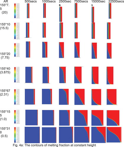
Figure 4 Continued
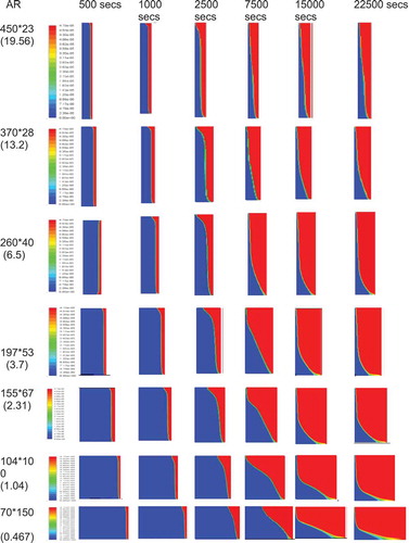
Figure 5 (a) The evolution of melt fraction with time for constant height case. (b) The evolution of melt fraction with time for constant volume case
shows the heat input rate from the hot water and heat loss rate to the cold water. For small aspect ratios (eg AR = 1) there is an imbalance between the heat input and heat lost. The heat input is much greater than the heat lost with the gap only reducing towards the end of the melt period. Indeed, AR1 for most of the time period, none of the heat input is lost from the system. This is because the PCM is absorbing all of the heat and melting. The remaining PCM acts as an insulating layer preventing heat loss. Only when the PCM Layer becomes thin does the heat loss rate increase.
Figure 6 (a) Evolution of heat transfer from hot water to PCM (heat input) and heat loss from PCM to cold water (heat loss) with time (constant height cases). (b) Evolution of heat transfer from hot water to PCM (heat input) and heat loss from PCM to cold water (heat loss) with time (constant volume cases)
Figure 6 Continued
Where the aspect ratios become high, the PCM layer is thin and it melts very quickly so that the impedance to heat transfer is reduced to a point that the heat input matches the heat loss rate and no further melting takes place
3.2.2 Constant volume (variable heating area) enclosure
For the case of constant volume, constant volume simulations were made for a number of aspect ratios in the range of 0.5–20 (AR = 0.467, 1.04, 2.31, 3.72, 5.11, 6.5, 13.21 and 19.57). The constant volume is equal to the volume of the rectangular enclosure used in the experimental case (AR = 2.31). The melting contours evolution are given in . The evolution of the melting percentage for these aspect ratio are plotted in .
Very similar behaviour was observed for the constant volume and height cases. It can be observed from the graphs in that the reduction in height for the cases of small aspect ratios (AR = 0.467 & 1.04) reduces the surface area available for heat input which lead to a slower melting rate compared to the higher ARs. However, the plots in indicate that melting rate starts off with linear relationship for all aspect ratios due to the conduction mode of heat transfer. The plot for the AR = 2.31 indicates that the optimum height for maximum heat can be absorbed by PCM is reached. Considering higher aspect ratios, AR = 5.11–19.57, the steady state heat transfer is reached faster.
The heat transfer balance can be summarised as:
where:
qadd: Heat added to the system from heated surface
qlat: Latent heat absorbed by PCM during melting
qsen: Heat absorbed by solid PCM below melting point
qsup: Heat absorbed by melted PCM at temperature higher than melting point
qloss: Heat transfer from cold surface
3.2.3 Comparing the effect of both approaches on melting collecting data at same times
To try to determine the optimum aspect ratio for melting, the melt percentages were plotted as a function of aspect ratio at different set times and are presented in and b. the peak in the melt percentage curve is an indication of the maximum melting efficiency and hence the optimum aspect ratio for melting.
Figure 7 Continued
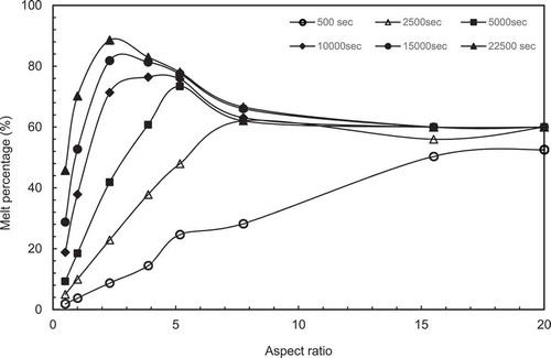
Figure 7 (a) Variation of melt percentage with aspect ratio (constant height case). (b) Variation of melt percentage with aspect ratio (constant volume case). (c) Variation of melt percentage with aspect ratio for both CH and CV cases. (d) Variation of heating surface area/PCM volume with aspect ratio for both constant height case (CH) and constant volume case (CV)
Figure 7 Continued
In , It is observed that the peak melting percentage is moved towards lower ARs with increased melting time. For example, the peak at AR = 20 for 500 secs, 7.75 for 2500 secs, 5.17 for 5000 & 10,000 and 2,31 for higher melting time.
In , it can be observed that the behaviour is different from the constant height cases. In these cases the peak melt percentages are not clearly defined for the long melt time
presents a comparison of melting percentage with AR between the constant height and constant volume cases at the longest melt time of 22,500 secs. It can be observed that the peak melting percentage is take place at AR = 2.31 for both cases. This behaviour can be explained by plotting the ratio of heating area/PCM volume with aspect ratio as given in . It can be observed that the surface area per unit volume for constant height is increased with aspect ratio and it becomes around 3 times the constant volume case at AR = 20.
To have a better understand of the interaction between the melting percentage, heat transfer and natural circulation, the maximum velocity for each AR were recorded simultaneously with melting percentage and heat transfer rate. The velocities were then plotted as a function of aspect ratio in and for the constant height case and constant volume case, respectively.
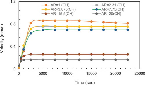
Figure 8 (a) Variation of maximum velocity with time for different aspect ratios (Constant height case). (b) Variation of maximum velocity with time for different aspect. Ratios (Constant volume case). (c) Variation of maximum circulation velocity time for 10 mm thickness and 2 different heights
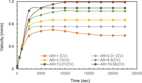
Figure 8 Continued
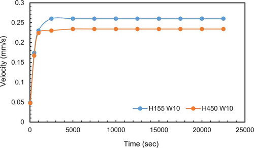
It can be observed from the maximum velocity reduced significantly for PCM (AR15.5 and above) which corresponds to a width less than 10 mm. This suggests the width is too small for boundary layers to form and therefore no significant circulation takes place. To confirm this width limitation of velocity, a second case of same width (10 mm) but with 450 mm height was simulated. The extra height would increase heat input and should increase the circulation velocity. compares the results from both cases. There is no significant increase in velocity confirming the limitation of due the PCM width. This is in line with the observations of the stagnant zone for the experimental work and confirms the choice of 3 mm as an appropriate distance for the boundary layer temperature measurement.
For the constant volume in , the velocity increased with height (higher AR) due to the increase in buoyancy effect but start decreasing for AR = 19.56 which corresponds to a thickness of 23 mm the reduction in velocity may also be attributed to the smaller width of the PCM enclosure.
4. Conclusion
In this work, a CFD model has been developed to investigate the effect of aspect ratio on melting process of the PCM materials. Simulation work has been carried out to investigate the effect of aspect ratio on melt rate of PEG 1500 for a fixed temperature difference of 60°C (80°C for hot surface, 20°C for cold surface). Simulations were performed for enclosures with different aspect ratio values whilst considering the case of constant height (AR = 20, 15.5, 7.75, 5.17, 3.875, 2.31, 1.0, and 0.5) and constant volume (AR = 19.57, 13.21, 6.5, 5.11, 3.72, 2.31, 1.04, and 0.467). The main conclusions can be summarised as:
The detailed investigation of the physics of the interaction between melting process, heat transfer and circulation highlighted the domination of conduction heat transfer in the first 250 secs. With the heat concentration at the upper part of the enclosure, the melting progressed due to convection heat transfer leading to gradual increase in melt percentage. The increase in melting is more pronounced when there is room for circulation to develop. This was predominant in the enclosures with lower aspect ratio which had constant height for enclosure and much wider width (low aspect ratio). It was also found that with high aspect ratio values, there is a steep increase in melting percentage at the initial stage of the heating process until steady state is reached. With this constant height in place, an increase in width of the PEG 1500 chamber, melting increases until steady state is attained.
An overlay of the predicted melting front with the experimental measurements shows that there is a good agreement in the result.
The interface shape changed from flat profiles at high aspect ratios (small PCM width) to concave shape at low Aspect Ratio (large PCM width) due to the change in heat transfer mechanism from conduction domination mode at small width to a signification contribution from natural circulation for large width (more than 10 mm) .
The melting percentage increased exponentially at the early stage of heating for aspect ratios greater than 2.31 before reduced to smaller melting rate. On the other hand, for aspect ratios less than 2.31, the melting percentage increase almost linearly as the melting progressed with time.
The results show that the heat transfer reached quasi-steady state condition in a shorter time for the cases with smaller enclosure width (large aspect ratio) compared to large enclosure width (small aspect ratio).
The results show that the maximum melting percentage is a function of time and aspect ratio. The maximum melting percentage moves from high aspect ratios at the initial stage of melting process to 2.31 for the maximum heating time of 22,500 sec used in this study
The results also show that there is a limiting width of the enclosure where the circulation velocity reduced to low values (<0.3 mm/s) regardless of the enclosure height.
5. Future work
The following works may be carried out in the future.:
The temperature distributions will need more experimental work to fully understand the evolution of the melting process and heat losses.
In order to model the energy balance across the enclosure, more thermocouples are needed on the heating plate.
The present study only examined the melting process of the PCM. This should be extended to the solidification process.
Manufacturing of the chambers needs to be improved to account for the expansion of the PCM and the expansion of the Perspex walls.
Disclosure statement
No potential conflict of interest was reported by the author(s).
Additional information
Notes on contributors
F. A. Hamad
Dr F.A.Hamad is Associate Professor in Engineering department, Teesside University. He studied BSc Mechanical Engineering and MSc Thermal Engineering at the University of Technology, Baghdad, Iraq. He worked for 10 years as a lecturer at Basrah University before he started his PhD study at Bradford University, UK on multiphase flow in vertical pipe. Dr Hamad has worked as a research Engineer for two years which extended for two years as a Teaching Fellow at the school of Engineering, Aberdeen University before he joined Teesside university as lecturer in 2011. Dr Hamad has published more than 60 papers in multiphase flow and heat transfer areas
E. Egelle
Dr E.Egelle is an Agile Project Manager and lecturer in Petroleum Engineering Department, Federal University of Technology Owerri. He studied Chemical Engineering at the Federal University of Technology Owerri Nigeria and masters in Oil and Gas Engineering at the Robert Gordon University Aberdeen. He did his PhD research on Heat Transfer in Chemical Engineering at Teesside University, Middlesbrough. He has worked for more than 9 years as a lecturer and have published more than 15 research papers.
S. Gooneratne
DrS.Gooneratne is a Principal Lecturer (Staffing & Resources: Engineering) at Teesside University. She completed her undergraduate studies at Churchill College, University of Cambridge, obtaining an MEng (Hons) degree in Chemical Engineering, and remailed there as a Cambridge Commonwealth Trust scholar to complete her PhD. She joined Teesside University in 2011 as a lecturer in Chemical Engineering. Samantha’s teaching and engineering research activities focus on reaction engineering and process simulation. She also has a significant interest in pedagogic research, and is passionate about the development of learning and teaching (L&T) pedagogy in engineering.
P. Russell
Dr P.Russell is a senior lecturer in Chemical Engineering at Teesside University. He completed his undergraduate studies and PhD at Aston University in 1998. Dr Russell spent a period of 18 months working in industry for BIP chemicals and Albright and Wilson. He then moved on to Loughborough University where he worked as a research fellow for 10 years on a series of EPSRC funded projects in the area of Flux Response Technology. Dr Russell moved to Teesside University in 2006 as a senior lecturer and became a chartered engineer in 2008. In 2015 he became an accreditation assessor for the Institution of Chemical Engineers. Dr Russell’s research interests are wide most recently he has been working in the area of three phase separation, heat transfer and hydrogen technologies. He is academic lead for phase two of an ERDF funded project to develop a hydrogen economy on Teesside.
References
- Al-Abidi, A. A., S. Mat, K. Sopian, M. Y. Sulaiman, and A. T. Mohammad. 2013. “Numerical Study of PCM Solidification in a Triplex Tube Heat Exchanger with Internal and External Fins.” International Journal of Heat and Mass Transfer 61 (1): 684–695. doi:https://doi.org/10.1016/j.ijheatmasstransfer.2013.02.030.
- ANSYS Fluent user guide, 2020, [Online]. Available: http://www.ansys.com/Industries/Academic/Tools/Citations
- Behbahan, A. S., A. Noghrehabadi, C. P. Wong, I. Pop, and M. Behbahani-Nejad. 2019. “Investigation of Enclosure Aspect Ratio Effects on Melting Heat Transfer Characteristics of Metal Foam/phase Change Material Composites.” International Journal of Numerical Methods for Heat & Fluid Flow 29: 2994–3011.
- Bouteldja, M., E. H. Mezaache, and A. Aouer. 2019. “Numerical Study of the Solidification of Phase Change Materials in a Rectangular Cavity: Effects of Convection and Aspect Ratio.” Annales de Chimie: Science des Materiaux 43 (1): 1–9. doi:https://doi.org/10.18280/acsm.430101.
- El Qarnia, H., A. Draoui, and E. K. Lakhal. 2013. “Computation of Melting with Natural Convection inside a Rectangular Enclosure Heated by Discrete Protruding Heat Sources.” Appl Math Modell 37 (6): 3968–3981. doi:https://doi.org/10.1016/j.apm.2012.08.021.
- Faraji, M., and H. El Qarnia. 2010. “Numerical Study of Melting in an Enclosure with Discrete Protruding Heat Sources.” Appl Math Modell 34 (5): 1258–1275. doi:https://doi.org/10.1016/j.apm.2009.08.012.
- Gadgil, A., and D. Gobin. 1984. “Analysis of Two-dimensional Melting in Rectangular Enclosures in Presence of Convection.” ASME J. Heat Transf 106 (1): 20–26. doi:https://doi.org/10.1115/1.3246636.
- Gau, C., and R. Viskanta. 1986. “Melting and Solidification of a Pure Metal on Vertical Wall.” ASME J. Heat Transf 108 (1): 174–181. doi:https://doi.org/10.1115/1.3246884.
- Goyal, P., V. Dutta, I. Verma, and T. Singh. 2013. Enthalpy Porosity Method for CFD Simulation of Natural Convection Phenomenon for Phase Change Problems in the Molten Pool and Its Importance during Melting of Solids, Trombay. Mumbai: Bhabha Atomic Research Centre.
- Hamad, F. A., E. Egelle, K. Cummings, and P. Russell. 2017. “Investigation of the Melting Process of Polyethylene Glycol 1500 (PEG 1500) in a Rectagular Enclosure.” International Journal of Heat and Mass Transfer 114: 1234–1247. doi:https://doi.org/10.1016/j.ijheatmasstransfer.2017.07.014.
- Ho, C. J., and R. Viskanta. 1984. “Heat Transfer during Melting from an Isothermal Vertical Wall, ASME J.” Heat Transf 106 (1): 12–19. doi:https://doi.org/10.1115/1.3246624.
- Joulin, A., Z. Younsi, L. Zalewski, S. Lassue, D. R. Rousse, and J. P. Cavrot. 2011. “Experimental and Numerical Investigation of a Phase Change Material: Thermal-energy Storage and Release.” Applied Energy 88 (7): 2454–2462. doi:https://doi.org/10.1016/j.apenergy.2011.01.036.
- Mbaye, M., and E. Bilgen. 2001. “Phase Change Process by Natural Convection-diffusion in Rectangular Enclosures.” Heat Mass Transfer 37 (1): 35–42. doi:https://doi.org/10.1007/s002310000095.
- Müslüm, A., E. Tütüncü, and A. Campo. 2018. “Numerical Investigation of Melting of Paraffin Wax Dispersed with CuO Nanoparticles 1 inside a Square Enclosure.” Heat Transfer Research 847–863. doi:https://doi.org/10.1615/HeatTransRes.2018019748.
- Pal, D., and Y. K. Joshi. 2001. “Melting in a Side Heated Tall Enclosure by a Uniformly Dissipating Heat Source.” Int J Heat Mass Transfer 44 (2): 375–387. doi:https://doi.org/10.1016/S0017-9310(00)00116-2.
- Shokouhmand, H., and B. Kamkari. 2013. “Experimental Investigation on Melting Heat Transfer Characteristics of Lauric Acid in a Rectangular Thermal Storage Unit.” Experimental Thermal and Fluid Science 50: 201–222. doi:https://doi.org/10.1016/j.expthermflusci.2013.06.010.
- Sridharan, P., 2013, “Aspect Ratio Effect on Melting and Solidification during Thermal Energy Storage.”
- Sundararajan, S., A. B. Samui, and P. S. Kulkarni. 2017. “Versatility of Polyethylene Glycol (PEG) in Designing Solid-solid Phase Change Materials (Pcms) for Thermal Management and Their Application to Innovative Technologies.” J. Mater. Chem. A 5 (35): 18379–18396. doi:https://doi.org/10.1039/C7TA04968D.
- Wang, Y., A. Amiri, and K. Vafai. 1999. “An Experimental Investigation of the Melting Process in a Rectangular Enclosure.” Int J Heat Mass Transfer 42 (19): 3659–3672. doi:https://doi.org/10.1016/S0017-9310(99)00024-1.
- Zhang, Y., Z. Chen, Q. Wang, and Q. Wu. 1993. “Melting in an Enclosure with Discrete Heating at a Constant Rate.” Exp Fluid Therm Sci 6 (2): 196–201. doi:https://doi.org/10.1016/0894-1777(93)90029-I.