
 ?Mathematical formulae have been encoded as MathML and are displayed in this HTML version using MathJax in order to improve their display. Uncheck the box to turn MathJax off. This feature requires Javascript. Click on a formula to zoom.
ABSTRACT
This research investigates the effects of snail shell-based hydroxyapatite (HAp) reinforcements on the mechanical, wear, and selected physical properties of epoxy-based composites. The exploitation of these properties was aimed at assessing the suitability and efficiency of the developed bio-composites for adhesive biomedical applications. Snail shell wastes were sourced and processed to obtain (HAp) particles of ˂20 μm. The bio-derived hydroxyapatite-based epoxy composites were produced using the stir-cast method by mixing the hydroxyapatite with the epoxy resin and hardener before pouring into the moulds where they are allowed to cure. Scanning Electron Microscope (SEM) and X-ray Diffraction (XRD) of the snail shell hydroxyapatite particles were carried out while mechanical, wear, and physical properties of the developed composites were evaluated. SEM images of the fracture surfaces were also examined. The results showed that enhancements occurred from the addition of snail shell-derived HAp to epoxy resin in the developed composites. The results revealed that most of the properties gave their optimum values when 15 wt.% reinforcement was used. At this weight fraction, optimum values were obtained which include 43 MPa for maximum flexural strength, 40HS for hardness, 40 J for impact, 0.35 W/mK for thermal conductivity, and 0.07 for wear index.
Introduction
Biomaterials are synthetic materials used as devices for the replacement of a living system and to function in intimate contact with living tissue. Orthopaedic implants are classified as biomaterials that are used for the replacement of damaged bones in the human body. Bones which include the femur, tibia, and fibula bone are replaced with materials that have high stiffness, biodegradability, high tensile and compressive strength, high yield and fatigue strength, biocompatibility, and high corrosive resistance (Ranter and Zhang Citation2020; Zhang et al. Citation2021). The attempt to replace damaged or amputated human bones has been birthed in the employment of several materials for biomedical implantation, some were effective while some had trial failure (Iftikhar et al. Citation2021).
Biomaterials in order to be biodegradable and biocompatible must display suitable properties for their applications in terms of strength, durability, and biological influence (Elakkiya et al. Citation2021). Metals and their alloys such as titanium, stainless steel, and cobalt-based alloys have been widely investigated for implant-device applications due to their excellent mechanical properties (Wang, Zhang, and Yao Citation2021). However, these metallic-based materials may also manifest biological issues such as toxicity, poor tissue adhesion, and stress shielding effect due to their high elastic modulus.
Polymer-based composite materials have been reported to be a potential material for the fabrication of biomedical implants because of their high stiffness, corrosion resistance, biodegradability, and biocompatibility (Luo et al. Citation2021; Jesuarockiam et al. Citation2019). Hydroxyapatite particles are considered a promising reinforcement material in the fabrication of bio-composites due to their effective use as a bone-graft material for creating strong chemical bonding between the biomedical implants and the host bone tissues (Wan et al. Citation2021; Oladele et al., Citation2019a). Also, due to the similar chemical structure of hydroxyapatite to natural bone, along with its bioactivity, osteoconductivity, and osteoinductivity, hydroxyapatite has been successfully applied in biodegradable polymer-based composites and metallic biomaterials (Agbabiaka et al. Citation2020; Andrew et al., Citation2018; Lin et al. Citation2011).
The dire need for improved biomedical materials at low cost cannot be overemphasised. Due to this fact, a growing need to develop biomaterials by utilising available agricultural wastes has been a research focus for many researchers (Agbeboh et al. Citation2020; Nayak et al. Citation2020). Though fewer research has been carried out for the conversion of agro-wastes to biocompatible and biodegradable products, the emergent agro-wastes that are employed for the production of hydroxyapatite serves as an alternative inorganic source for bones and tooth replacements and grafting due to their similar bio-mineral constituents and are expected to continue to stimulate the interest of researchers worldwide (Oladele et al. Citation2018).
Adhesive biomaterials have had a wide range of applications in all medical fields due to the extensive variety of biomaterials with different adhesion properties (Zaokari, Persaud, and Ibrahim Citation2020). The field of orthopaedics has enjoyed many benefits from using adhesives that can provide superior biocompatibility, resorbability, and low immunogenicity. The areas of applications of adhesive biomaterials in orthopaedics are as filler materials to treat bone defects, as carrier materials to deposit other bioactive materials to a site, and as scaffolds. The need for adhesive biomaterials has been on the rise as they can be applied to virtually any application. Methods like sutures, staples, and clips are often used to close wounds but these methods had several limitations over which adhesive materials can offer some benefits (Lauto, Mawad, and Foster Citation2008). Other non-adhesive biomaterials can be difficult to use due to the possibility of causing damage to surrounding tissue when applied and can be time-consuming. Adhesives were not studied extensively until the 1900s when adhesive sealants used for haemostasis were developed (Kazemzadeh-Narbat, Annabi, and Khademhosseini Citation2015). One of the initial documented studies was done with naturally derived adhesives (Zaokari, Persaud, and Ibrahim Citation2020). Since then, more research is being carried out in this field of study because adhesive biomaterials can offer an effective alternative to current methods being used in all clinical fields. This research was carried out to develop a bio-derived hydroxyapatite-based composite for adhesive biomedical applications using epoxy resins as matrix and snail shell-based HAp as reinforcements. This was done in order to develop sustainable adhesive biomaterials with ease of use without impairing the function of the surrounding tissue.
Materials and methods
Materials
The materials used for the research include the following: Epoxy Resin and Hardener that were supplied from Malachy Enterprise, Lagos State, Nigeria. Snail shell from white shelled snail (Archatina Manginatta) sourced from farmland in Akure, Ondo State, Nigeria. Distilled water and Orthophosphoric acid from Pascal Scientific, Akure.
Methods
Preparation of the snail shell hydroxyapatite
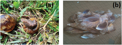
The sourced snail shell wastes were thoroughly washed and dried to remove impurities. They were then crushed and ground before being sieved to obtain ˂50 μm snail shell particles. showed the image of snail and snail shells.
Plate 1: (a) White-shelled snail (archatina manginatta) and (b) Snail shell.
The conversion of the 50 μm grounded snail shells to CaO followed the steps reported by Agbabiaka et al. (Citation2020). In the first stage of the calcination process, a heating rate of 7°C/min was used to heat the snail shells from room temperature to 550°C and held for 2 hours. In the second stage, a heating rate of 5°C/min was used to heat-treat up to 700°C with a holding time of 2 hours while in the third stage, a heating rate of 4°C/min was used to heat the shells to 1000°C and was held for 1 hour at 1000°C. At this stage, the snail shells were now transformed into calcium oxide () by evolving carbon dioxide (
). The
was formed through the following equation:
The produced from the calcined snail shell was further converted into hydroxyapatite in an orthophosphoric acid (H3PO4).
A stoichiometric amount of the calcined sample was dispersed in a beaker containing 100 ml of distilled water placed on a hot plate maintained at 90°C for 2 hours. A 20 ml of analytical grease of orthophosphoric acid was added to the beaker and stirred at 120 rpm. Initially, a suspension was observed following which the solution became clear after about 30 minutes of mixing. The PH value of the solution was kept below 2 by adding drops of sodium hydroxide solution as required. The solution was aged for 7 days, filtered and the residue was dried at 105°C for 1 hour in an oven. Thereafter, the dried residue was heated to 1000°C in a furnace at 150°C/min for 1 hour. Finally, the lumped hydroxyapatite solids formed were manually ground into powders and sieved to obtain ˂20 μm particle sizes. The equation of reaction is shown in Equationequation (2)(2)
(2)
The synthesised snail shell-derived hydroxyapatite was as shown in .
Plate 2: Synthesised snail shell derived hydroxyapatite.
Fabrication of snail shell derived hydroxyapatite composites
The snail shell-derived hydroxyapatite reinforced epoxy composite samples were fabricated by the stir cast moulding process. The bio-derived HAp/epoxy composites were produced by randomly dispersing 3, 6, 9, 12, and 15 wt.% hydroxyapatite particles in epoxy resin (in ratio 2:1 with its hardener). A total of 350 g was used to determine the mass of the matrix and reinforcement in the production of the composites with the formulation shown in . Unreinforced epoxy-based sample, designated as the control was first produced for the basis of comparison and the development of the composites.
Table 1. Mass ratio of the developed epoxy bio-composites
Characterisation and evaluation of snail shell and developed composites
XRD Analysis
X-Ray diffraction (XRD) pattern of the snail shell particles was carried out to determine the phases present in the particles by taking measurements within the range of using a Shimadzu XDS 2400 H diffractometer with 40 mA, 45 VA and 240 mm with a copper Kα radiation source. The machine was operated at generator settings of 30 kV and 20 mA at a temperature of 25°C and the patterns were analysed using PANalytical (v3.0e) X’pert High score software.
Tensile test
Tensile testing on the samples was conducted on a universal testing machine (UTM, FS 300–1023, USA) at a crosshead speed of 5 mm/min. The test was carried out at room temperature and in accordance with ASTM D-638-14 (Citation2014) standard. Specimen dimension is based on Type IV specification with an overall length of 115 mm with a thickness of 3 mm. Three replicates of each tensile sample were fabricated for the tensile test. An average value was calculated from the results to aid the plotting of the tensile graphs.
Flexural test
Flexural test on the sample was examined on a universal testing machine (UTM FS 300–1023, USA) according to ASTM D-790-15 (Citation2015) standard. Three samples from each lot were tested in accordance with the standard. The test specimen had a dimension of 150 × 50 x 3 mm and was hooked on the grip of the machine. The test speed was 5 mm/min over a span of 65 mm and the obtained results were analysed afterwards. Three replicates of each flexural sample were fabricated for the flexural test from where the average value was further calculated to aid the plotting of the flexure graphs.
Hardness test
A digital Shore Hardness Tester was used to perform the hardness test. The hardness of each material was measured and determined by the hardness tester instrument and expressed as HRC. For each hardness measurement, six indentations were made and each indentation was implemented at different points on each specimen. The average value was determined to provide the mean value hardness for each selected material. A load of 15 kg was applied to each specimen with 15s dwell time. The samples were indented in five different locations from where the average values were further calculated to aid the plotting of the graph.
Impact test
The notched Izod impact test was conducted in accordance with ASTM D256-10 (Citation2018) standardised test method for determining the Izod Pendulum impact resistance of plastics. The test was carried out using a Hounsfield balanced impact testing machine, serial number 3915, model number h10-3. Impact test samples with a dimension of 64 × 11 x 3 mm were notched at the centre. Samples were placed horizontally on the machine, maintaining a distance of 60 mm between lines of supports. The test samples were placed on a cantilever position clamped upright with a V-notch at the level of the top of the clamp. The machine pendulum hit the test piece and was allowed to fall freely to a fixed height. Also, three replicates of each impact sample were fabricated for the impact test from where the average values were calculated to aid the plotting of the graph.
Wear test
The wear resistance of the samples was examined using a Taber abrasion tester (TABER Rotary Platform Abrasion Tester – Model 5135, USA) in accordance with ASTM D4060-10 standard. A centre hole of 10 mm was made on the sample to fix the test piece on the machine. The sample was secured to the instrument platform that is a motor driven at 500 rpm. Each specimen was a flat round disc of approximately 100 mm in diameter and a standard thickness of approximately 6.35 mm. ASTM D4060-10 standard was used to calculate the wear resistance as loss in weight at a specified number of abrasion cycles (500). A set of two rotating abrasive wheel of thickness (12.6 mm) and diameter (50 mm) was run against the test samples and were subjected to a contact load of 1000 g. The rotational speed of operation was set at 500 rpm for about 1000 cycles. The wear indices were calculated based on the sample weight loss as shown in Equationequation (3)(3)
(3) .
where Wi, Wf and C are initial weight, final weight, and number of test cycles, respectively.
Thermal conductivity test
Thermal conductivity test was carried out using the Lee’s disk apparatus to determine the thermal conductivity of the developed composite in accordance with ASTM E1530-19 (Citation2019). The thermal conductivity analysis was carried out at a temperature range of 50°C–80°C and at such, no temperature or thermal degradation was noticeable as the material developed was not tested at a temperature close to the activation of degradation. To determine the thermal conductivity of the samples, EquationEquation 4(4)
(4) was used.
where K is the thermal conductivity, M is the mass of the disk, 0.0078 kg, Cp is the specific heat capacity of the disk, 0.91 kJ/kg K, Φ1 and Φ2 are the initial and final temperature of the disk B, D is the diameter of the sample (0.04 m), X is the thickness of the sample, 0.003 m, T1 and T2 are the temperature of disk A and B in Kelvin and, t is the final time taken to reach a steady temperature.
Water absorption test
Water absorption tests were carried out in accordance with ASTM D5229M-12 (Citation2012). To carry out the test, 250 cl of water media was poured into clean plastic containers. The initial weight of each of the samples was taken using chemical weighing and readings were taken every day for 30 days. To take the readings, the samples were brought out, cleaned with clean cloth before weighing. The data collected were used to determine the weight gained using the formula in EquationEquation (5)(5)
(5) .
where W (g) is weight gain per day, Wo is the oven-dry weight and Wt is the weight of the sample after time (t).
Microscopy characterisation
The SEM micrograph characterisation for the fracture surfaces of the samples were carried out using EVO MA 15, Carl Zeiss SMT. Samples were gold sputtered to improve electrical conductivity.
RESULTS AND DISCUSSION
XRD Analysis and SEM images of snail shell derived HAp particles
The XRD analysis of the snail shell powder was carried out using a Shimadzu XDS 2400 H diffractometer with 40 mA, 45 VA, and 240 mm tube current, voltage rating, and goniometer radius, respectively, attached to a digitised computer along with graphical assembly on uncompressed powders to collect the maximum of the diffraction lines and better identification of the phases. The powdered sample was prepared using the sample preparation block and compressed in the flat sample holder to create a flat, smooth surface. The sample was later mounted on the sample stage in the XRD cabinet. The X-ray of Cu Kα radiations was collimated and directed onto the sample. Then, the powdered sample was analysed using the reflection-transmission spinner stage and Theta–Theta settings scanning range of 4 to 75.000 degrees with a two-theta step of 0.026 at 13.7700 seconds per step. The intensity of the diffracted X-rays is continuously recorded automatically on a chart and the appropriate θ and (d) values were then obtained as the sample and detector were rotated through their respective angles.
Fixed anti-scatter and divergence slits of ¼o were used together with a beam mask of 10 mm. All scans were carried out in continuous mode using a detector. The d (111) spacing (Ǻ) was determined using the Bragg’s law shown in Equationequation 6(6)
(6) .
where λ is the Kα wavelength and 2θ is the peak value at the 2θ o axis.
The diffractogram for the samples were obtained. The background and peak-positions were identified and based on the peak positions and intensities; a search-match routine was performed.
The obtained experimental patterns were compared to standards compiled by Joint Committee on Powder Diffraction and Standards (JCDPS), while the 2-theta angles, d-spacing, and relative intensities are shown in . XRD spectra of the sample specimen are shown in the diffractogram (Plate 4). As it is seen from the diffractogram in Plate 4 that there are no crystalline peaks at the lower region in this graph which confirms the amorphous nature of the samples and exhibited a typical crystalline glass phase pattern with a glass hump. The SEM micrographs of the snail shell-derived hydroxyapatite particles is as shown in Plate 5.
Plate 3: XRD diffraction pattern of snail shell derived HAp particles.
Plate 3: SEM Image of snail shell derived HAp particles.
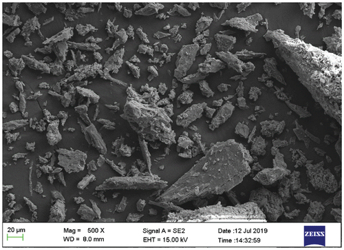
Table 2. XRD diffraction peaks of snail shell-derived HAp particles
Tensile properties
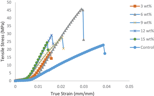
The tensile stress–strain curves for samples are as shown in , where it was noticed that the control sample possess the highest strain properties compared to the developed bio-composites. Hence, unreinforced epoxy demonstrated the highest plasticity potential compared to the developed bio-composites. However, the bio-composites possess improved tensile strength than the unreinforced epoxy. Thus, the bio-composites have the potential to withstand higher stress than the unreinforced epoxy that serves as control in the research. The bio-composite with 6 wt.% HAp was the best among the composites with a value of 46 MPa and 0.029 mm/mm ultimate tensile strength and strain, respectively, compared to the control with 22 MPa and 0.038 mm/mm. It was noticed that 6 wt.% HAp reinforced epoxy bio-composite displayed a good combination of stress-strain properties compared to both the control and other bio-composites. This revealed that, the influence of reinforcement content on developed composites is vital in composite development since optimum properties are noticed to be strongly determined by the amount of reinforcement added in addition to other salient factors. Hence, more attention should be given to the influence of reinforcement content on the desired properties from the developed composites.
Figure 1. Influence of snail shell-based HAp particles on the tensile stress–strain curve of the developed bio-composites and the control.
shows the variation of the addition of HAp reinforcements on the tensile properties. It was observed that there was an enhancement in the maximum tensile strength and Young’s Modulus of the developed samples with the addition of snail shell-derived HAp reinforcement when compared to the control sample as noticed in . The 6 wt.% HAp reinforced composite possesses the highest tensile strength with a value of 46 MPa while 12 wt.% HAp reinforced composite possessed the highest Young’s Modulus with a value of about 1031 MPa. These optimum values are due to the reasons stated in . The 6 wt.% reinforced composite sample achieved 103.8% enhancement when compared to the control sample with a value of 22 MPa while about 136% increase was attained for 12 wt.% reinforced composites in terms of Young’s Modulus when compared to the control sample that possesses a value of 451 MPa. These enhancements indicated in the reinforced composites might have occurred due to the presence of CaCO3 in the snail shell-based HAp. Oladele et al. (Citation2019b) in their study reported that enhancement in tensile strength was highly supported by the presence of particulate CaCO3 in the developed hybrid composites which agreed with the findings of this work. Padmanabhan et al. (Citation2015) in their study on synthesis and characterisation of collagen scaffolds reinforced by snail shell-derived hydroxyapatite also confirmed that the increase in density (weight fraction) of epoxy composites decreases the tensile strength. Therefore, the reduction in tensile properties observed between 6 wt.% and 12 wt.% may be due to the increase in weight fractions. Several research outputs (Oladele et al., Citation2019b; Padmanabhan et al. Citation2015) has shown that weight fraction has a strong influence on the properties of composites and, hence, the reason several research is still being carried out to determine the reinforcement content with optimum value (Oladele et al. Citation2021). Tensile Modulus tends to increase as the HAp content increases from 3 to 15 wt.% HAp addition. There was no significant enhancement when 3 wt.% was added until 6 wt.% (974 MPa) which supports the reason why 6 wt.% HAp addition gave the optimum tensile strength as observed in . It is also evident from that the stiffness trend agreed with these results. Hence, the addition of snail shell-derived HAp into epoxy bio-composites improves the tensile properties.
Figure 2. Effect of the addition of snail shell-based HAp particles on the tensile properties of epoxy bio-composites.
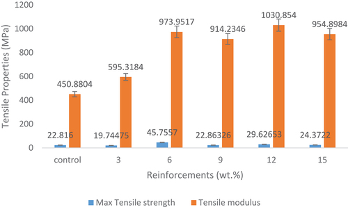
Figure 3. Tensile strain at maximum tensile strength of the control and snail shell-based HAp reinforced samples.
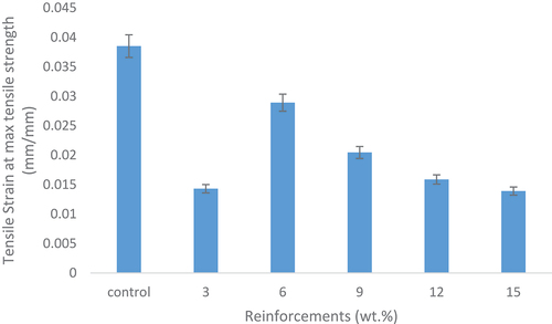
reveals the variation of the tensile strain at maximum tensile strength with respect to the reinforcement content and the control. The control sample has the longest strain at maximum tensile strength; thus, enhancements did not occur. The control sample when compared to the reinforced sample has a relatively high strain rate with an optimum value of 0.038 mm/mm. It was discovered that the strain rate decreased as the reinforcement content increase which showed that the addition of the HAp increases the strength and stiffness of the materials. The absence of enhancements in the strain rate of the developed composites may have occurred due to the presence of strong and stiff hydroxyapatite particles (CaCO3) within the matrix. The 6 wt.% reinforced composite possessed the highest tensile strain rate when compared to the other reinforced composites with a value of 0.029 mm/mm as shown in .
Flexural properties
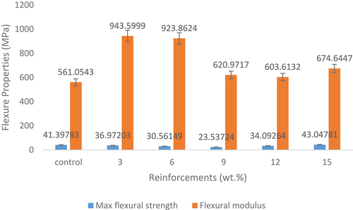
shows the effects of snail shell-based HAp on the flexural properties of the composites. There was a decrease in the flexural strength as the HAp content increased from 3 to 9 wt.% prior to an increase from 12 to 15 wt.% HAp addition. It was noticed from the results that there was a slight enhancement in the maximum flexural strength with the addition of 15 wt.% HAp as reinforcement in the composite. The 15 wt.% reinforced composite experienced the optimum maximum flexural strength property with a value of 43 MPa indicating about a 4% increase when compared to the control sample that has a value of 41 MPa. These observed trends still confirm the influence of reinforcement content on the properties of composites. It also follows that the addition of 15 wt.% HAp meets the required quantity needed for improved flexural strength in addition to other factors that are common to all the developed samples. It was discovered that there is a limited enhancement in the bending strength of the materials that showed that the addition of this HAp did not improve the bending strength of the developed composites. However, for the flexural modulus, high enhancements occurred. The initial increment from 3 to 6 wt.% was followed by a sharp decrease from 9 to 15 wt.% HAp addition. HAp reinforced epoxy bio-composite with 3 wt. % possessed the optimum flexural modulus with a value of about 944 MPa indicating a 68% increase when compared to the control sample. By obtaining the optimum flexural modulus at the lowest HAp content and slight increase in maximum flexural strength at 15 wt.% HAp addition implies that small quantity of the HAp is needed for improved flexural properties. Other reasons for the results obtained might be due to what was explained in .
Figure 4. Effect of the addition of snail shell-based HAp particles on flexural properties.
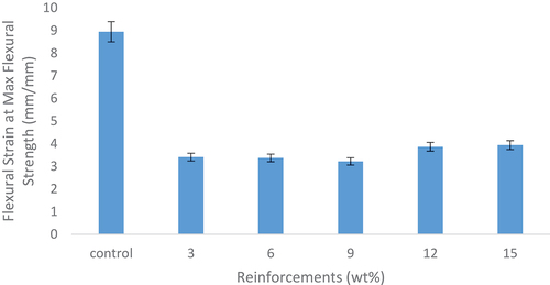
shows the effects of snail shell-derived HAp on flexural strain at maximum flexural strength of the developed composites. There was no enhancement on the reinforced composites when compared to the control sample and this indicates that the reinforced composites possess lower strain rate as compared to the control sample. The developed bio-composites have low flexural strain tendencies compared to the control. The reason for this occurrence is similar to what is observed in .
Figure 5. Flexural strain at maximum flexural strength of the control and snail shell-based HAp reinforced samples.
Hardness properties
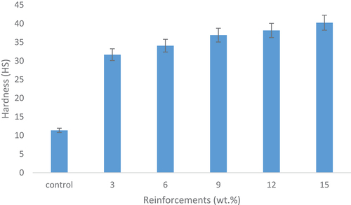
shows the effects of snail shell-derived HAp on the hardness of the developed samples. It can be clearly observed that the hardness increases simultaneously with the weight fraction. The 15 wt.% showed the best enhanced hardness properties with an optimum value of 40 HS revealing a 254% increase from the control sample. The increase in hardness can be traced to the increase in density of the composite caused by the increase in the weight fraction of the snail shell-derived HAp. Thus, the hardness property of snail shell-derived HAp reinforced epoxy composites increases with an increase in weight fraction and this statement agrees with the findings of Oladele and Isola (Citation2016) in which they confirmed that high density enhances higher material hardness.
Figure 6. Effects of the addition of snail shell-based HAp particles on hardness property of the samples.
Impact energy
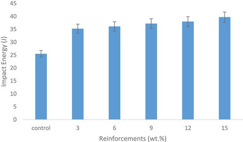
The effects of snail shell-derived HAp on impact energy are shown in . It was observed that the impact energy increases as the weight fraction increased from the 3–15 wt.% HAp content. This increase in impact energy with simultaneous increase in weight fraction occurred due to the increase in density. The 15 wt.% HAp reinforced epoxy bio-composite emerged as the weight fraction with the most enhanced impact energy having a value of about 40 J indicating a 35% increase from the control sample. The control sample possessed the lowest amount of impact energy with a value of about 26 J. Teboho et al. (Citation2018) in their study confirmed that the increase in the weight fraction improves impact energy.
Figure 7. Effect of the addition of snail shell-based HAp particles on the impact energy of the developed bio-composites and the control.
Wear property
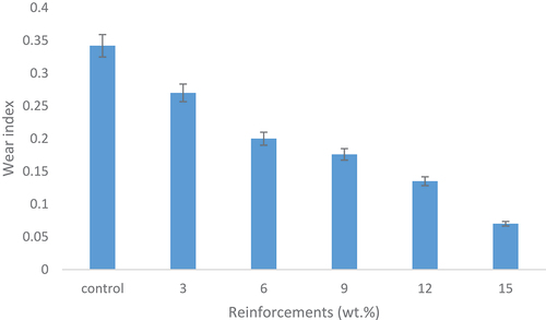
The wear resistance of the samples was calculated based on their wear index. This wear resistance is related to their mechanical properties in terms of their surface characteristics. shows the effects of snail shell-derived HAp on wear index for the developed composites and the control. The results revealed that wear resistance increases as the reinforcement content increases from 3 to 15 wt.%. This improvement in the wear index occurred due to the constant reduction in the coefficient of friction as the weight fraction increased from 3 to 15 wt.% yielding low frictional force. The resulting low frictional force existing from the increase in weight fraction agreed with Oladele et al. (Citation2019a) in their study on the structural performance of poultry eggshell-derived hydroxyapatite based high-density polyethylene bio-composites in which they concluded that the inclusion of HAp significantly enhances the wear resistance. Also, the low frictional force had been proved to occur in reinforced epoxy composites due to the presence of reinforcements which possess high density than the epoxy matrix (Ramesh et al. Citation2014). From the results, it was observed that the control sample possessed the highest wear index, and the value reduces gradually till the 15 wt.% HAp additions indicating 80% decrease. Thus, the 15 wt.% HAp reinforced epoxy bio-composites possessed the highest wear resistance with an optimum value of 0.07. The reduction in wear index indicates increase in wear resistance properties which is also due to increase densification from the HAp reinforcement and proper wetting/adhesive bonding that exist between the HAp and the epoxy resin.
Figure 8. Effect of the addition of snail shell-based HAp particles on wear resistance.
Thermal conductivity properties
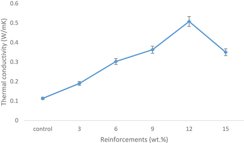
shows the thermal conductivity of the composites and the control sample. It was observed that the thermal conductivity of the developed bio-composites increases as the HAp content increases from 3 to 12 followed by a decrease at 15 wt.% HAp contents. Thus, sample with 12 wt.% snail shell-derived HAp reinforced epoxy bio-composite possess the highest thermal conductivity with a value of 0.5076 W/Mk. It was clearly shown that the thermal conductivity of the control sample experienced the lowest value when compared to the reinforced samples with a value of 0.1134 W/mK. Hence, about 348% increase in thermal conductivity was experience from the control sample to the 12 wt.% reinforced composite. There was also a slight decrease in the thermal conductivity from the 12 wt.% to the 15 wt.% revealing a 45% decrease. From the results, it was evident that the inclusion of this bio-derived HAp aided the thermal conductivity of epoxy which suggests that this material can be utilised if properly modified as thermally conductive material. This and other agro-based materials could be processed as alternative sources to the synthetic materials currently used, thus, promoting the development of biodegradable and sustainable materials for electronics applications.
Figure 9. Effect of the addition of snail shell-based HAp particles on thermal conductivity.
Water absorption properties
The variation of water absorption properties for the control and snail shell reinforced epoxy bio-composites is shown in . The results reveal the behaviour of the samples when immersed in water medium against time. It can be observed from the results that as the reinforcement weight fraction increases, the weight gained by the composite samples increases from 3 to 15 wt.%. All the samples were found to absorb water rapidly and linearly at the initial stage before the saturation level was attained on the 27th day where further increase in water absorption was not noticeable till the day 31st day. Water aids the transmitting of oxygen and ions, hence, diffusion of water in polymers is an important mechanism that involves intensive attention (Oliveira et al. Citation2016; Hincke et al. Citation1995).
Figure 10. Variation of water absorption properties on the snail shell-based HAp reinforcements.
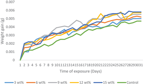
From the results, the rate of water absorption from day 1 to day 15 was rapid which shows a steep slope on the curve while from day 16 till day 24, there was a linear and gradual rate of water absorption that indicated a near saturation of the samples. At day 25 till day 31, it was observed that the samples were saturated all through. There was a flat and saturated mode in the curve. It was discovered that the addition of HAp encourages the diffusion of liquid within the composites more than the control samples. Hence, 15 wt.% HAp reinforced sample possessed the highest weight gain among all the composite samples which implies adequate permeability of fluid. This is an essential property expected from biomaterials for effective body fluid transmission.
SEM Images of the developed bio-composites
The SEM images showed the morphology of the fractured composites samples as presented in Plates 6–10.
showed the SEM image of the bio-composite sample with 3 wt.% snail shell-derived HAp. It revealed a uniform dispersion of the snail shell-derived HAp in the epoxy matrix with less amount of HAp compared to other weight fractions. This led to a low agglomeration and the inclusion of pores in the 3 wt.% bio-composite sample. This low amount of HAp contributed to the observed properties.
The SEM image of the bio-composite sample with 6 wt.% snail shell-derived HAp is shown in . It was observed that a more visible and optimum even dispersion occurred in the matrix when compared to the 3 wt.% bio-composite samples. This more visible dispersion observed in indicates an increase in the weight fraction and this increase led to the presence of small agglomeration and de-bonding when compared to , . The more visible and even dispersion that occurred in was the major reason for the optimum enhancements observed in the tensile properties of the 6 wt.% bio-composite sample as shown in ().
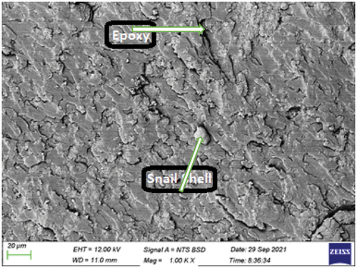
Plate 8 shows the SEM image of the bio-composite sample with 9 wt.% snail shell-derived HAp. At this high content of HAp, a more pronounced agglomeration and de-bonding occurred when compared to and ). These observed features contributed to the reasons for poor properties noticed with this sample.
The SEM image of the bio-composite sample with 12 wt.% snail shell-derived HAp is shown in . This reveals an increase in the quantity of snail shell-derived HAp with an even dispersal in the epoxy matrix. This increase in the quantity (weight fraction) observed in is responsible for the simultaneous increase in the hardness, impact, wear, thermal conductivity, and water absorption properties as shown in . Also, the formation of clustered lumps of snail shell-derived HAp in the matrix led to the optimum enhancement in the thermal conductivity properties as shown in .
shows the SEM image of the bio-composite sample with 15 wt.% snail shell-derived HAp. The SEM image revealed a well uniformly dispersed high weight fraction of HAp in the epoxy. This feature was responsible for the improved properties observed from most of the properties examined. High content of the HAp with proper dispersion and adhesion within the epoxy aid adequate transfer of load from the matrix to the reinforcement and, thus enhanced properties. Unlike other weight fractions where agglomerations and voids were noticed/well pronounced, there is good blend at this weight fraction.
It can be seen from the SEM images (Plates 6–10) that the adhesive property of epoxy resin was part of the reasons for proper interfacial adhesion at the HAp/epoxy resin interphase that produced improved properties at various weight fractions.
Plate 6: Bio-composite sample with 3 wt.% snail shell derived HAp.
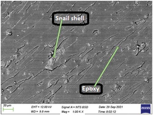
Plate 7: Bio-composite sample with 6 wt.% snail shell derived HAp.
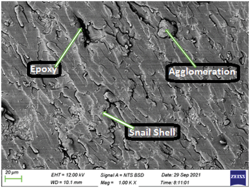
Plate 8: Bio-composite sample with 9 wt.% snail shell derived HAp.
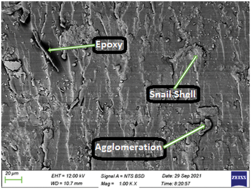
Plate 9: Bio-composite sample with 12 wt.% snail shell derived HAp.
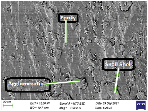
Plate 10: Bio-composite sample with 15 wt.% snail shell derived HAp.
Conclusion
This research presented the synthesis and characterisation of snail shell-derived HAp for use in epoxy matrix composites for adhesive biomaterials applications. It was discovered from the results that the developed bio-composites had improved mechanical, wear, thermal conductivity and water absorption properties. These results showed that snail shell-derived HAp are potential materials for the fabrication of adhesive biomaterials with epoxy resin that can be suitably used for orthopaedic applications. Among the various HAp content used, 15 wt.% was the fraction with the optimum values in most of the properties; flexural strength (43 MPa), hardness (40 HS), impact (40 J), wear index (0.07), and water absorption potential. Hence, both the HAp synthesis method and the weight fractions that gave optimum values in most of the properties considered can be used for biomedical applications by the industry.
Acknowledgments
This work was supported through the AESA-RISE Fellowship Program [ARPDF 18-03], African Materials Science and Engineering Network (A Carnegie-IAS RISE network) and the DST-NRF Centre of Excellence in Strong Materials. AESA-RISE is an independent funding scheme of the African Academy of Sciences (AAS) implemented with the support of Carnegie Corporation of New York. At The AAS, AESA-RISE is implemented through AESA, the Academy’s agenda and programmatic platform, created in collaboration with the African Union Development Agency (AUDA-NEPAD). The views expressed in this publication are those of the author(s) and not necessarily those of the AAS, AUDA-NEPAD or Carnegie Corporation.
The services of Dr. M. O. Bodunrin of the Department of Chemical and Metallurgical Engineering, University of the Witwatersrand, South Africa, in carrying out SEM analysis are appreciated.
Disclosure statement
No potential conflict of interest was reported by the author(s).
Additional information
Funding
Notes on contributors
Isiaka Oluwole Oladele
Isiaka Oluwole Oladele is a Lecturer, Researcher, and Associate Professor in the Department of Metallurgical and Materials Engineering, Federal University of Technology, Akure with a specialization in Composite Materials and Polymer Technology.
Linus Onuh
Linus N. Onuh is a graduate of the Department of Metallurgical and Materials Engineering, Federal University of Technology, Akure with a specialization in Polymer Composite Development.
Anuoluwapo Samuel Taiwo
Anuoluwapo Samuel Taiwo is a Lecturer and Doctoral Researcher in the Department of Metallurgical and Materials Engineering, Federal University of Technology, Akure and Enhanced Composites and Structures Centre, School of Aerospace, Transport, and Manufacturing, Cranfield University Cranfield United Kingdom respectively with specializations in Composite Development, Polymer Technology, and Cementitious Materials.
Sunday Borisade
Sunday Gbenga Borisade is a Lecturer and current Ph.D. Researcher in the Department of Materials and Metallurgical Engineering, Federal University Oye-Ekiti, Ekiti State, Nigeria, and Department of Metallurgical and Materials Engineering, Federal University of Technology, Akure respectively with specializations in Composite Development and Polymer Technology.
Newton Itua Agbeboh
Newton Itua Agbeboh is a Lecturer, and Researcher in the Department of Mechanical and Mechatronics Engineering, Federal University Otuoke, Ogbia, Bayelsa State, Nigeria with specializations in Composite Development and Polymer Technology.
Senzeni Sipho Lephuthing
Senzeni Sipho Lephuthing is a Lecturer, and Researcher in the Department of Metallurgy, University of Johannesburg, South Africa with specializations in Composite Development and Polymer Technology.
References
- Agbabiaka, O. G., I. O. Oladele, A. D. Akinwekomi, A. A. Adediran, A. O. Balogun, O. G. Olasunkanmi, and T. M. A. Olayanju. 2020. “Effect of Calcination Temperature on Hydroxyapatite Developed from Waste Poultry Snail Shell.” Scientific African Journal 8: 1–12. https://eprints.lmu.edu.ng/id/eprint/2808.
- Agbeboh, N. I., I. O. Oladele, O. O. Daramola, A. A. Adediran, O. O. Olasukanmi, and M. O. Tanimola. 2020. “Environmentally Sustainable Processes for the Synthesis of Hydroxyapatite.” Heliyon 6 (4): 1–13. doi:10.1016/j.heliyon.2020.e03765.
- Andrew, J. J., A. Vellayaraj, and D. Hom Nath. 2018. “Repair of Polymer Composites: Methodology, Technique and Challenges.” Composites Science and Engineering: 1–43. Duxford, United Kingdom: Woodhead Publishing.
- ASTM D256-10. 2018. Standard Test Methods for Determining the Izod Pendulum Impact Resistance of Plastics. West Conshohocken, PA: ASTM International.
- ASTM D4060-10. 2010. Standard Test Method for Abrasion Resistance of Organic Coatings by the Taber Abraser. West Conshohocken, PA: ASTM International. 2010.
- ASTM D5229M-12. 2012. Standard Test Method for Moisture Absorption Properties and Equilibrium Conditioning of Polymer Matrix Composite Materials. West Conshohocken, PA: ASTM International.
- ASTM D638-14. 2014. Standards Test Method for Tensile Properties of Plastics. West Conshohocken, PA: ASTM International.
- ASTM D790-15. 2015. Standard Test Methods for Flexural Properties of Unreinforced and Reinforced Plastics and Electrical Insulating Materials. West Conshohocken, PA: ASTM International.
- ASTM E1530-19. 2019. Standard Test Method for Evaluating the Resistance to Thermal Conductivity by the Guarded Heat Flow Meter Technique. West Conshohocken, PA: ASTM International.
- Elakkiya, S., G. Arthanareeswaran, A. F. Ismail, P. S. Goh, and Y. Lukka Thuyavan. 2021. “A Review on Characteristics of Biomaterial and Nanomaterial Based Polymeric Nanocomposite Membranes for Seawater Treatment Application.” Environmental Research 197: 111177. doi:10.1016/j.envres.2021.111177.
- Gonzálezl, J., C. Albano, M. V. Candal, M. Hernández, M. N. Ichazo, M. A. Mayz, and A. Martínez (2005). “Study of Composites of PP and HDPE with Seashells Treated with LICA 12.” Proceeding of the 8th Polymers for Advanced Technologies International Symposium, Budapest, Hungary. 11–15.
- Hincke, M. T., J. L. Arias, Y. Nys, J. M. Garcia-Ruiz, and S. E. Solomon. 1995. “Avian Snail Shell Mineralization.” Poultry and Avian Biology Reviews 10: 143–166.
- Iftikhar, S., N. Jahanzeb, M. Saleem, S. Rehman, J. P. Matinlinnna, and A. S. Khan. 2021. “The Trends of Dental Biomaterials Research and Future Directions: A Mapping Review.” The Saudi Dental Journal 33 (5): 229–238. doi:10.1016/j.sdentj.2021.01.002.
- Jesuarockiam, N., M. Jawaid, E. S. Zainudin, M. T. Hameed Sultan, and R. Yahaya. 2019. “Enhanced Thermal and Dynamic Mechanical Properties of synthetic/natural Hybrid Composites with Graphene Nanoplateletes.” Polymers 11 (7): 85. doi:10.3390/polym11071085.
- Kazemzadeh-Narbat, M., N. Annabi, and A. Khademhosseini. 2015. “Surgical Sealants and High Strength Adhesives, Mater.” Today 18 (4): 176–177. doi:10.1016/j.mattod.2015.02.012.
- Lauto, A., D. Mawad, and L. J. R. Foster. 2008. “Adhesive Biomaterials for Tissue Reconstruction.” Journal of Chemical Technology and Biotechnology 83 (4): 464–472. doi:10.1002/jctb.1771.
- Lin, K., X. Liu, J. Chang, and Y. Zhu. 2011. “Facile Synthesis of Hydroxyapatite Nanoparticles, Nanowires and Hollow Nano-structured Microspheres Using Similar Structured Hard Precursors.” Nanoscale, Procedia Materials Science 3 (8): 3052–3055. https://pubs.rsc.org/en/content/articlelanding/2011/nr/c1nr10334b.
- Luo, M., X. Zhang, J. Wu, and J. Zhao. 2021. “Modifications of Polyasaccharide-Based Biomaterials under Structure-Property Relationship for Biomedical Applications.” Carbohydrate Polymers 266: 118097. doi:10.1016/j.carbpol.2021.118097.
- Nayak, S. Y., M. T. H. Sultan, S. B. Shenoy, C. R. Kini, R. Samant, A. U. M. Shah, and P. Amuthakkannan. 2020. “Potential of Natural Fibers in Composites for Ballistic Applications–A Review.” Journal of Natural Fibers 1–11. https://doi.org/10.1080/15440478.2020.1787919
- Oladele, I. O., and B. A. Isola. 2016. “Development of Bone Particulate Reinforced Epoxy Composite for Biomedical Application.” Journal of Applied Biotechnology and Bioengineering 1 (1): 35–40. doi:10.15406/jabb.2016.01.00006.
- Oladele, I. O., O. G. Agbabiaka, O. G. Olasunkanmi, A. O. Balogun, and M. O. Popoola. 2018. “Non-synthetic Sources for the Development of Hydroxyapatite.” Journal of Applied Biotechnology and Bioengineering 5 (2): 92–99. doi:10.15406/jabb.2018.05.00122.
- Oladele, I. O., O. G. Agbabiaka, A. A. Adediran, A. D. Akinwekomi, and A. O. Balogun. 2019a. “Structural Performance of Poultry Egg Shell Derived Hydroxyapatite Based High-Density Polyethylene Bio-composites.” Heliyon 5 (10): e02552. doi:10.1016/j.heliyon.2019.e02552.
- Oladele, I. O., O. I. Ibrahim, A. D. Akinwekomi, and S. I. Talabi. 2019b. “Effect of Mercerization on the Mechanical and Thermal Response of Hybrid Bagasse fiber/CaCO3 Reinforced Polypropylene Composites.” Polymer Testing 76: 192–198. doi:10.1016/j.polymertesting.2019.03.021.
- Oladele, I. O., T. F. O. Omotosho, G. S, and F. A. Owa. 2021. “A Review on the Philosophies for the Advancement of Polymer-based Composites: Past, Present and Future Perspective.” Applied Science and Engineering Progress 14(4): 1–27.
- Oliveira, I. R., T. L. Andrade, K. C. M. L. Araujo, A. P. Luz, and V. C. Pandolfelli. 2016. “Hydroxyapatite Synthesis and the Benefits of Its Blend with Calcium Aluminate Cement.” Ceramics International 42 (2): 2542–2549. http://dx.doi.org/10.1016/2Fj.ceramint.2015.10.056.
- Padmanabhan, S. K., L. Salvatore, F. Gervaso, M. Catalano, A. Taurino, A. Sannino, and A. Licciulli. 2015. “Synthesis and Characterization of Collagen Scaffolds Reinforced by Snail Shell Derived Hydroxyapatite for Tissue Engineering.” Journal of Nanoscience and Nanotechnology 15 (1): 504–509. doi:10.1166/jnn.2015.9489.
- Ramesh, M., T. Sri-Ananda Atreya, U. S. Aswin, H. Eashwar, and C. Deepa. 2014. “Processing and Mechanical Property Evaluation of Banana Fiber Reinforced Polymer Composites.” Procedia Engineering 97: 563–572. doi:10.1016/j.proeng.2014.12.284.
- Ranter, D., and G. Zhang . 2020. “A History of Biomaterials.” Biomaterials Science 21–34. (4th edition). https://doi.org/10.1016/B978-0-12-816137-1.00002-7
- Teboho, C. M., J. M. Mokgaotsa, E. M. Tshwafo, Z. L. Linda, M. T. Oriel, and P. S. Sandile. 2018. “Sugarcane Bagasse and Cellulose Polymer Composites.” Technology and Research 12: 225–241. doi:10.5772/intechopen.71497.
- Wan, M., W. Qin, C. Lei, Q. Li, M. Meng, M. Fang, W. Song, J. Chen, F. Tay, and L. Niu. 2021. “Biomaterials from Sea.” Future Building Blocks for Biomedical Applications, Bioactive Materials 6 (12): 4255–4285.
- Wang, Y., W. Zhang, and Q. Yao. 2021. “Copper-Based Biomaterials for Bone and Cartilage Tissue Engineering.” Journal of Orthopedic Translation 29: 60–71. doi:10.1016/j.jot.2021.03.003.
- Zaokari, Y., A. Persaud, and A. Ibrahim. 2020. “Biomaterials for Adhesion in Orthopedic Applications: A Review.” Engineered Regeneration 1: 51–63. doi:10.1016/j.engreg.2020.07.002.
- Zhang, D., Q. Chen, C. Shi, M. Chen, R. Liu, R. Liu, and R. Liu. 2021. “Dealing with the Foreign-Body Response to Implanted Biomaterials: Strategies and Applications of New Materials.” Advanced Functional Materials 31 (6): 2007226. doi:10.1002/adfm.202007226.