
 ?Mathematical formulae have been encoded as MathML and are displayed in this HTML version using MathJax in order to improve their display. Uncheck the box to turn MathJax off. This feature requires Javascript. Click on a formula to zoom.
Abstract
In a global context of simultaneous urbanization and rising ambient temperatures, it is imperative to design heat-resilient and material-efficient neighbourhoods that respond to the pressing demand for housing with minimal environmental impact. With this goal in mind, the work presented here focuses on the integration of heat dissipation systems within structural building components, introducing a novel framework for their systems-level simulation and design. Two well-studied, low-cost systems (shallow geothermal and night-sky cooling) are modelled within a parametric design workflow that combines bottom-up structural embodied carbon calculations with annual building energy simulations that account for heat sink availability. The proposed method results in a fast and reliable early-stage design tool that allows urban planners, policymakers, and designers to evaluate the suitability of available heat dissipation technologies across climates and urban morphologies. This paper analyzes specifically the multi-domain performance of a hypothetical urban geometry within three different cooling-dominated locations (Algiers, Cairo, and Bangkok).
Nomenclature
| A | = | area (m2) |
| d | = | thickness (m) |
| E | = | efficiency (-) |
| F | = | view factor (-) |
| f | = | fraction of evaporation rate (-) |
| h | = | heat transfer coefficient (W/m2) |
| k | = | thermal conductivity (W/m°C) |
| n | = | cloud cover factor (-) |
| q | = | heat flux (W/m2) |
| Q | = | cooling energy, total heat dissipated (kWh) |
| r | = | pipe radius (m) |
| ra | = | relative humidity (%) |
| t0 | = | soil surface phase constant (sec) |
| t0,a | = | air phase constant (sec) |
| S | = | net solar radiation (W/m2) |
| T | = | temperature (°C) |
| U | = | overall heat transfer coefficient (W/m2°C) |
| z | = | soil depth (m) |
| αs | = | soil's thermal diffusivity (m2/s) |
| β | = | soil's absorption coefficient (1 – albedo) |
| cp | = | specific heat (J/kg°C) |
| ε | = | emissivity (-) |
| = | mass flow rate (kg/s) | |
| ϕl | = | phase constant between insolation and air temperature (rad) |
| ω | = | angular frequency |
| ΔR | = | long-wave radiation constant (W/m2) |
Subscripts
| C | = | convection |
| cs | = | clear sky |
| dp | = | dew-point |
| eff | = | effective |
| f | = | fluid |
| exch | = | exchange |
| m | = | mean |
| rad | = | radiator |
| s | = | soil, surface |
| v | = | amplitude |
1. Introduction: urbanization in a warming world
Cities are becoming warmer and denser worldwide, with shifting climatic conditions and continuous migration processes from rural to urban areas. This reality is particularly critical in Africa and Asia, concentrating 90% of the predicted global urbanization by 2050 (World urbanization prospects Citation2019) and the majority of cities with high exposure to extreme heat events (Citation2018). In this context of simultaneous urbanization and rising temperatures, it is crucial to design low-cost, climate-adapted neighbourhoods that respond to the pressing housing demand with minimal environmental impact. This multi-faceted challenge requires holistic solutions that jointly tackle climate change adaptation and mitigation. With this goal in mind, the work presented here focuses on the integration of heat dissipation systems within building structural elements, introducing a framework for their systems-level simulation and design. More broadly, the question becomes how to leverage the building's structural frame (a substantial and unavoidable material investment) as an effective heat sink that reduces operational carbon emissions and contributes to a cooler built environment.
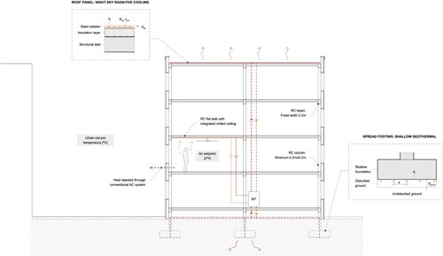
Among the available array of heat-dissipation technologies, this paper prioritizes those ready to be deployed at scale, affordable, and easy to integrate with other building components, as they are most suitable for contexts with limited economic resources and urgent construction needs. Two well-studied, low-tech systems are selected for this paper: shallow geothermal through the building's foundations and roof-integrated radiative cooling (). In both cases, the underlying concept is the same: warm water is pumped through a piping circuit embedded within a reinforced concrete building element (a spread footing, the roof slab) and is cooled when in contact with a heat sink (the ground, the night sky). This colder water is then stored in a tank and recirculated into the building when needed, absorbing the space's excess heat through a radiant panel that can also be integrated into the building's structure (Gascón Alvarez et al. Citation2022). More complex and energy-intensive versions of this scheme, suitable for very hot climates and not included in this work, include a water-to-water heat pump that heats water on the condenser side (the ground and sky heat exchangers) and cools water on the evaporator side for thermal comfort.
Figure 1. Selected heat dissipation systems for a hypothetical multi-story residential building. After removing heat from the conditioned spaces, hot water is stored first and pumped afterward to either the foundations or the roof to be cooled down through the available heat sink (the ground or the night sky)..
In summary, this paper proposes a method for the early-stage design of heat dissipation systems integrated within structural elements, assessing their material and cooling impact at an urban level. Neighbourhoods with a reduced material footprint facilitate access to affordable housing and efficient cooling strategies alleviate the health risks associated with extreme heat events. From a climate-change mitigation perspective, the potential benefits are significant: structure components typically account for 50% of buildings’ total embodied carbon emissions (Kaethner and Burridge Citation2012), while the carbon associated with cooling has tripled from 1990 to 2016 and is expected to increase as global temperatures rise (Citation2018).
2. Previous work
2.1. Integrated, low-energy heat dissipation strategies
The design of integrated heat dissipation elements has been extensively studied in academia and industry as a resource-efficient approach that allows collapsing multiple functions into a single building component. Selecting the appropriate low-energy cooling technology typically responds to a combined qualitative and quantitative assessment of the element´s multi-faceted performance under specific climatic conditions. Radiative cooling systems are commonly integrated into roofs, given their high exposure to the sky vault. Possible solutions range from unglazed plate collectors activated through water pipes (Dimoudi and Androutsopoulos Citation2006; Hosseinzadeh and Taherian Citation2012) with cooling rates of 40-87 W/m2 for night operation (Zhao et al. Citation2017), photovoltaic-thermal systems (PVT) that produce electricity and cooling energy (Eicker and Dalibard Citation2011), or daytime cooling panels integrated into attic spaces (Zhao et al. Citation2019) (with an average cooling power of 45 W/m2 at noon). Evaporative cooling strategies can be further incorporated into facade elements through, for example, textile-based skins that allow for rainwater harvesting (Eisenbarth et al. Citation2022) or porous materials (Timmer Citation2021). Finally, the buried substructure can serve as a ground cooling device in deep foundations for example, borehole heat exchangers integrated into concrete piles (Brandl Citation2006) or shallow foundations (Nam and Chae Citation2014). In the mentioned examples, affordability is studied by, for example, measuring the materials’ accessibility, cost (environmental and economic), or fabrication constraints. However, few examples assess the material efficiency of the solutions iteratively across options, missing opportunities for multi-objective design frameworks.
2.2. Multi-domain urban design workflows
The densification of cities and its associated urban heat island (UHI) effect can harm the effectiveness of the heat dissipation systems analyzed in the previous section. Surrounding buildings, for instance, might block the view of radiative panels to the sky vault (Mokhtari, Ulpiani, and Ghasempour Citation2022), whereas subsurface warming decreases the chances of dissipating heat through the ground (Bayer et al. Citation2019). Thus, it becomes necessary to adequately model these strategies in a multi-scalar way, accounting for the interrelations between urban geometry and heat-sink availability. This approach aligns with current efforts toward the development of fully comprehensive simulation frameworks for urban energy sustainability, as highlighted in the review conducted by Mauree et al (Mauree et al. Citation2019). The authors describe the importance of modelling the intrinsically multi-dimensional nature of cities, establishing connections between urban microclimate conditions, outdoor thermal comfort, energy systems, and buildings´ energy demand. While multiple programmes have tackled two or more of these topics jointly such as CitySim (Emmanuel and Jérôme Citation2015), UMI (Reinhart et al. Citation2013), UrbanSolve (Nault et al. Citation2018) or the City Energy Analysis tool (Fonseca and Schlueter Citation2015), none includes (as far as the authors know) the systems-level design of integrated heat dissipation strategies, linking their performance with the city's urban form and microclimate and with buildings’ resilience to heat.
2.3. Research opportunity
UN SDG11′s goals for ‘sustainable cities and communities’ evidence the need for multi-domain design workflows that lead to integrated policies and plans towards inclusion, resource efficiency, mitigation, and adaptation to climate change (target 11.b). Focusing on contexts with high urbanization rates and threatening temperature rises, the question of designing cities for combined material and cooling efficiency is an under-studied yet highly relevant topic. This challenge demands a new approach to urban design tools that bring together building massing and component design, establishing connections and identifying synergies between them. The presented work contributes through an innovative method that allows for evaluating the performance of heat dissipation strategies at an early decision stage through the lens of systems integration and impact across scales. More specifically, this research combines first-order analytical calculations with geometry-dependent numerical simulations to provide fast and reliable parametric studies. The method is applied here to two low-cost heat dissipation technologies but is conceived as a flexible framework that can be extrapolated to other systems and contexts.
The paper´s structure is organized as follows: (1) Section 3 introduces the multi-domain workflow, describing the models and tools used at each step; (2) Section 4 applies the described method to a hypothetical residential development, conducting a parametric study across three different climates; (3) Section 5 summarizes the contributions of this work and discusses its applicability to other contexts, focusing on opportunities for future developments.
3. Method for systems-level design and simulation
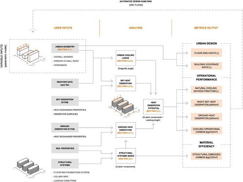
The methodology proposed in this section allows urban planners, architects, and policymakers to assess the suitability of urban heat dissipation technologies – in this paper, shallow geothermal and night-sky cooling – and the possibility of integrating them within the building's structural frame. In this way, the environmental performance of urban developments can be holistically assessed from an early design stage, jointly accounting for its heat dissipation ability and material impact. Figure summarizes the different steps of the proposed method, each of which is covered in detail in the following subsections.
Figure 2. The proposed workflow allows for an early-stage evaluation of integrated urban heat sinks (in this paper, shallow geothermal through the foundations and a roof night sky radiator) and associated material impact.
3.1. Massing proposal
The tools and models presented in this work are implemented within the visual programming software Grasshopper, which runs within the Rhinoceros 3D computer-aided design (CAD) application. This platform is well-known for parametric 3D modelling in the architecture, engineering, and construction (AEC) industry and allows for a straightforward integration between existing environmental software plugins, the software's 3D-modelling tools, and the new Python-based components developed in this work. Alongside the building massing process (either free-form or parametric), two urban design parameters are tracked: floor area ratio (FAR), the ratio of total built floor area to the plot area, and plan area density (λp), the ratio of building footprint to the same plot area (Oke et al. Citation2017). The former is a standard proxy for density and the latter (also referred to as building coverage ratio (BCR) in urban design literature) assesses the amount of open area available for other uses.
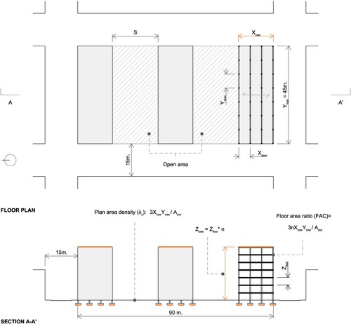
In this study, a hypothetical residential development located within a mid-density urban context is evaluated in three different locations, each of them corresponding to a different Köppen-Geiger climate zone (Beck et al. Citation2018): Bangkok (A, Tropical), Cairo (B, Arid), and Algiers (Csa, Temperate with hot summer). Figure shows the considered plot, an area of 4050 m2 with three separate blocks built in parallel and two resulting open spaces in between. The longitudinal dimension of each building is fixed at 45 m, and the width Xtotal and total height Ztotal are defined as variable inputs. While not necessarily representative of the existing urban fabrics, this generic urban morphology allows for focusing on the abovementioned urban design parameters and analyzing in isolation their impact across the metrics presented in this work. Concerning the structural system, the number of columns and beams depends on these massing parameters as well as a pre-defined range for the structural span of the chosen programme (5 to 7 m, in this paper). The sizing of these elements and other main structural elements is conducted using the method presented in the following section.
Figure 3. Geometric definition of the analyzed neighbourhood. Two urban design metrics – floor area ratio (FAR) and plan area density λp (also known as Building Coverage Ratio or BCR) – are calculated in the parametric worflow. Aplot refers to the area of the whole site (including the two open areas) and n to the number of floors.
3.2. Structural system design: foundation sizing
Building foundations are responsible for resolving the loads of a building to the soil below. The structural material required and resulting surface area of foundations for ground heat dissipation, Af, depends on the mass of the superstructure, which changes with building height, loading, and material selection (among other variables). While more surface area results in more potential for heat dissipation, this comes at the expense of more materially intensive (and therefore environmentally costly) foundations than are required structurally. The aim of this paper is to demonstrate the effectiveness of utilizing the building's necessary structural components as a heat sink. As such, the method presented simulates the design process of a practicing structural engineer, and accounts for the minimum structural material necessary to safely transmit the building loads to the soil, following the applicable building codes.
In order to determine the available surface area for ground heat dissipation, a gravity load-resisting structural system is designed using physics-based analytical equations and results from previous constrained optimization workflows by Ismail and Mueller (Ismail and Mueller Citation2021). At the same time, this workflow quantifies the total structural material quantities through bottom-up calculations, in order to track the embodied carbon of the respective designs. Structural carbon has the potential to contribute significantly to a buildings’ total carbon emissions over a 50-year lifespan (typical period evaluated in a Life Cycle Assessment (LCA) (Ji, Lee, and Yi Citation2021)), depending on the massing and climate. In this case study, the embodied carbon of the sub- and super-structure is tracked due to the fact that these elements typically account for more than half of a buildings’ total embodied carbon (Kaethner and Burridge Citation2012). The environmental impact of non-structural components (such as internal walls, services, and finishes) is not evaluated as design decisions regarding these components are typically not established at early-stage design.
In this paper, embodied carbon (CO2e) refers to the carbon emitted during LCA stages A1-A3 according to EN 15978:2011 (See Sec. 3.1), otherwise known as Cradle to Gate processes. Embodied carbon coefficients for world averages are used from the Inventory of Carbon and Energy (Hammond and Jones Citation2008) due to the reliability of these values (Moncaster and Song Citation2012) (See Table ), and bottom-up calculations are used due to their accuracy for estimates of urban-scale carbon emissions (Weber, Mueller, and Reinhart Citation2020).
Table 1. Material properties for structural design and embodied carbon calculation *(Hammond and Jones Citation2019).
The various structural components are designed in reinforced concrete (RC), due to its global availability and prominence (Allwood and Cullen Citation2015). This research references the National Building Code (NBC) of India for structural mechanics, (IS 456) (Bureau of Indian Standards Citation2000) as the aforementioned constrained optimization workflows (Ismail and Mueller Citation2021) were developed specifically for this location. NBC can be compared to American Concrete Institute Code 318-19 but is more conservative in some regards (Ismail and Mueller Citation2021), although both are based on similar understandings of concrete failure modes and behaviours. A building programme is selected, informing the preliminary column grid and the live load resisted by the structure (as well as cooling operational carbon, discussed in Section 3.3). In this case, multi-family residential programme is studied, resulting in a uniformly distributed live load of 1.9 kN/m2 (The International Building Code Citation2015) and a superimposed dead load of 1kN/m2.
The RC floor slabs, a common system for the abovementioned spans, are designed using the constrained optimization methodology developed by Ismail and Mueller (Ismail and Mueller Citation2021). The resulting concrete mass, mc, and reinforcing steel mass, ms, for the respective span is then extracted by fitting a two-degree polynomial curve to the data obtained from sampling over 500 designs using this method. This mass is used to design the RC beams and columns for the tributary floor area they are supporting, following the simplified mechanics-based methods outlined by Arroyo Portero et al. (Arroyo Portero et al. Citation2009). It is worth pointing out that other floor slab materials and more efficient typologies are available, such as shape-optimized or thin-vaulted RC slabs (López et al. Citation2014; Hawkins et al. Citation2020; Ismail and Mueller Citation2021), which may offer higher carbon savings potential. However, in this paper, flat, one-way spanning RC floor slabs are chosen to evaluate a typology that is ubiquitous in construction in many parts of the world. The lateral load-resisting system is not considered for the building heights sampled (up to 10 stories). It is assumed that lateral stiffness is not the controlling factor for design (D’Amico and Pomponi Citation2020) and can be considered separately.
Spread footings are modelled due to their ubiquity in global construction. Physics-based analytical equations for calculating the concrete and reinforcing steel are used to size the footings using established engineering methods outlined by Kurian (Kurian Citation2004) for sandy soils (bearing capacity, q = 96 kN/m2) (International Code Council Citation2020). Each footing is designed for the building mass being supported for the respective tributary area. Once designed, the surface area Af, is extracted for calculating the heat exchange potential. The slab-on-grade is not being considered, however, this warrants further study as it has been shown that this potential is dependent on the floor build-up and climate (Brearley Citation2022). The total structural material quantities of concrete and reinforcing steel for the respective samples (including floor slabs, beams, columns, and foundations) are extracted and multiplied by their respective density and embodied carbon coefficient (ECC) (See Table ) to determine the environmental impact of the structural system, normalized by the gross floor area (GFA) for comparison.
3.3. Urban heat sink evaluation
Once the neighbourhood's general massing and structural system have been selected, defining the available surfaces for heat dissipation, the different heat sinks are assessed through first-order evaluation methods that allow for quick iterations and comparisons across design proposals. The presented method relies on a combination of analytical tools and fast numerical calculations that provide enough accuracy for early-stage urban massing processes and can be easily implemented in parametric design workflows. The cooling energy Q of each dissipation system is evaluated using the general form presented by Alvarez et al (Alvarez, Maestre, and Velazquez Citation1997), which accounts for a working fluid at Tinlet that is in contact with a heat sink (the ground or the night sky) at Tsink.
(1)
(1) where the efficiency of the sink Esink is defined as a function of an intermediate temperature Teff:
(2)
(2) and the efficiency of the heat exchanger Eexch with area A as:
(3)
(3) For given fluid properties (assumed here to be water at flow rate
), the effective and sink temperatures Teff and Tsink, and overall heat transfer coefficient U become critical to determining the efficiency of the sink and exchanger. The next lines describe the process to find these values for the selected systems.
3.3.1. Ground dissipation system: shallow geothermal
The availability of the ground as a heat sink results from its ability to dampen seasonal temperature fluctuations, staying cooler than ambient conditions during summer and warmer during winter. Ground temperatures can be approximated as harmonic functions that reduce their amplitude as depth increases, reaching, at a certain distance, a constant temperature equal to the mean annual surface temperature Tm = Tsink_ground. In this paper, soil surface temperature conditions are estimated using the model developed by Krarti et al (Krarti et al. Citation1995), which was found to predict experimental data from five locations with an average discrepancy of ten percent. This analytical method is based on the energy balance at the surface level and assumes an undisturbed ground with homogeneous thermal properties. For soil conditions with heterogeneous thermal properties or significant disturbances from underground infrastructure (a district heating network or an aquifer, for example), more complex models based on numerical simulations or on-site data measurements would need to be implemented.
According to the selected analytical model adding the phase constant of the soil surface t0, as defined in (Lee and Strand Citation2006) the temperatures at depth z for a soil with thermal diffusivity αs is defined as:
(4)
(4) where:
(5)
(5)
(6)
(6) As observed, the mean surface temperature Tm, temperature amplitude Tv, and phase shift ϕs are the three parameters that define the sinusoidal curve of interest, analyzed at a frequency ω. These values are obtained from the boundary conditions at the soil surface, which include convective heat exchange, long-wave radiation, solar insolation, and evaporative energy. As shown in the sensitivity analysis of the original model (Krarti et al. Citation1995), lower soil surface temperatures are achieved for higher wind velocities (higher hs), higher evaporation rates f, lower relative humidity values ra, and lower soil absorptivity β.
(7)
(7)
(8)
(8)
(9)
(9)
As cities become denser, soil temperatures are expected to rise due to increased urban air temperatures and reduced heat dissipation through long-wave radiation. On the contrary, the decrease in solar insulation due to the shadowing between buildings will counteract the overheating to a certain extent. To account for these geometry-dependent effects, the following numerical calculations are introduced:
The mean air temperature Tma, temperature amplitude Tva, and relative humidity ra values are extracted from a morphed weather file that accounts for the Urban Heat Island (UHI) effect at an atmospheric level. As explained in the next subsection, the urban weather generator (UWG) model (Bueno et al. Citation2013) is implemented within the proposed workflow through the Dragonfly plugin (Charan et al. Citation2021).
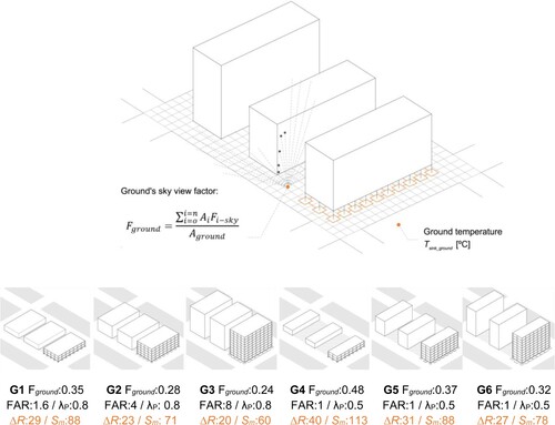
Similarly, the Ladybug toolset is used to compute the mean solar insolation Sm, its amplitude Sv, and the long-wave radiation constant ΔR on the meshed surface surrounding the buildings of analysis (see Figure ). The ‘LB Incident Radiation’ component is used to calculate the first two values, while the latter is obtained from the following expression:
(10)
The phase angle difference ϕl between the air temperature and insolation values is extracted from fitting sinusoidal curves to the corresponding set of sparse data obtained in the previous points.
Additionally, these phenomena are influenced by the soil cover and moisture content, which determine the fraction of evaporation rate f, absorption coefficient β (approximated as one minus the surface albedo), and the soil surface's emissivity εground. The remaining values included in equations 7-9 (he, hr, and b) are chosen following the literature guidelines (Krarti et al. Citation1995).
Figure 4. The ground sky view factor Fground is computed as the weighted average of the view factors Fi-sky calculated for each cell Ai within the meshed surface. The analyzed urban designs illustrate how the mean solar radiation Sm and the long wave radiation constant ΔR diminish as the ground's view factor reduces.
At a component level, this research investigates the potential of integrating horizontal ground heat exchangers HGHE (Naili et al. Citation2013) within shallow concrete foundations, more specifically spread footings. The surface area Af of these elements will largely depend on the structural system selected, soil capacity, and the sizing process (see section 3.2). The overall heat transfer coefficient Uground for a generic HGHE with adequate spacing s between pipes and area of contact AHGHE = 2πrL (and L = Af /s) can be defined as:
(11)
(11) where 1/hf corresponds to the fluid's convective resistance within the pipe, and r/kground ln(r+dground/r) to the conductive resistance of the first layer of disturbed ground (for a 24 h cycle) with thickness (Krarti and Kreider Citation1996):
(12)
(12) Finally, it is important to highlight that the proposed method does not account for the long-term effects of heat injection into the ground nor the interaction between neighbouring HGHE. Both phenomena could potentially increase the ground temperatures over time (Miglani, Orehounig, and Carmeliet Citation2018), decreasing the system's overall performance. Future stages of this work should include the consideration of seasonal regeneration strategies (extracting heat for space heating during winter, or producing domestic hot water, among others) and guidelines on the adequate spacing between integrated HGHE at a neighbourhood scale. Along these lines, recent research presents novel frameworks for estimating the technical potential of borehole heat exchangers (BHE), considering their spatial interaction and season regeneration through heat injection (Walch et al. Citation2022).
3.3.2. Sky dissipation system: roof-integrated night-sky cooling
The availability of the night sky as a heat sink through longwave radiation is influenced by multiple atmospheric conditions, most importantly the relative humidity. As the presence of water vapour in the atmosphere decreases, Tsink_sky becomes cooler thanks to the sky's lower emissivity. In this paper, Tsink_sky is calculated using the method proposed by Argiriou et al (Argiriou, Santamouris, and Assimakopoulos Citation1994), which is based on the sky emissivity correlation found by Berdhal and Martin (Berdhal and Martin Citation1984):
(13)
(13)
(14)
(14)
(15)
(15)
Equations Equation13(13)
(13) and Equation14
(14)
(14) show that the main parameters of the mentioned sky emissivity model are the dew-point temperature Tdp and the cloud cover factor n (n = 0 for a clear sky, and n = 1 for an overcast sky). The effective temperature Teff can be then defined as the minimum threshold temperature the radiator can achieve at a reference ambient temperature Ta:
(16)
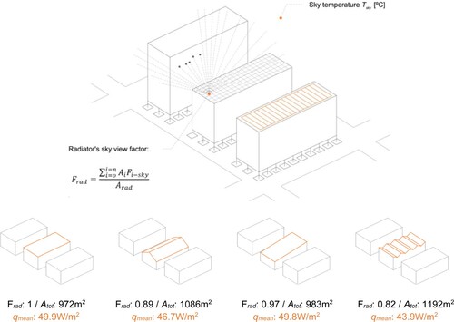
(16) As observed, the radiator's net radiative power qo is linearly proportional to its emissivity εrad and view factor Frad. This latter value represents the fraction of view from the radiator surface that is occupied by the sky vault, which highly depends on the context geometry (see Figure ), and is computed through the ray-tracing methods available in the open-source environmental design tool Ladybug (Sadeghipour Roudsari and Pak Citation2013). Only surfaces with an average Frad > 0.7 are considered, as any value below that is considered detrimental for the radiator's performance. On the other hand, the effective heat transfer coefficient he results from adding the convective coefficient hconv (3.5W/m2K for wind speeds below 0.5 m/s, and as 2.8+0.76v for v>0.5 m/s) (Clark and Berdahl Citation1981) to the equivalent radiative coefficient.
The system's overall heat transfer coefficient Usky is derived from the pipe's convective heat transfer hf, the conductive resistance of the radiator plate (with area Arad), and the above-mentioned coefficient he.
(17)
(17) This low-energy cooling strategy can be installed as an independent panel (Mihalakakou, Ferrante, and Lewis Citation1998) or, as shown in Figure , integrated into a roof component (Meir, Rekstad, and LØvvik Citation2002; Dimoudi and Androutsopoulos Citation2006) through a metallic plate with area Arad that simultaneously serves as a radiator, water-proofing layer, and even pavement for an accessible outdoor space. The system operates exclusively at night, storing cold water in a storage tank used during the day for cooling purposes. It is assumed that the radiator has a low heat capacity and an insulation layer underneath it such that all solar radiation absorbed during the daytime is released into the surrounding air before starting to pump the warm water at night.
Figure 5. The radiator sky view factor Frad is computed as the weighted average of all the view factor Fi-sky calculated for each cell Ai within the meshed surface. The analyzed roof geometries illustrate how the mean heat dissipation qmean diminishes as the roof's exposure to the sky reduces due to neighbouring buildings or its self-shadowing.
3.3.3. Urban cooling loads
After computing the total heat dissipation potential, the system performance can be assessed in relation to the building's cooling requirements and urban context. The natural cooling saving fraction (NCSF) is a metric commonly used in the evaluation of low-energy cooling techniques (Guerrero Delgado, Sánchez Ramos, and Álvarez Domínguez Citation2020) to correlate the total heat dissipation Qdiss to the building cooling loads Qloads:
(18)
(18) The utilization factor F considers the dynamic effects between the two heat transfer processes (space cooling and heat rejection) and quantifies their impact on the heat sinks’ availability. This value is calculated following the building standard ISO 52016 (ISO Citation2017), expressed as a function of the zone's time constant and heat-balance ratio. The building's thermal loads Qloads are computed monthly using EnergyPlus for an all-air HVAC system and a mixed-mode operation. Cooling setpoints are set to 27°C for the air temperature, with the presumption that ceiling fans will provide sufficient indoor air speed to achieve comfort at the mentioned temperature. The building's programme and envelope characteristics are introduced at this stage, as well as the epw weather file extracted from the UWG model. This latter simulation is run for the analyzed urban geometry through the Dragonfly plugin, accounting for the energy exchanges of the selected buildings with the canyon's air, surrounding road and context, and the urban boundary layer (UBL).
One of the key parameters of the UWG model is the anthropogenic heat fluxes released into the urban environment, which significantly impact the rise in temperatures attributed to the UHI effect. Among these, frcanyon captures the fraction of heat dissipated by buildings’ HVAC systems into the urban canyon. This value is defined here as frcanyon = 1-NCSF, assuming that the heat that is not dissipated to either the ground or the night sky will reach the urban canyon. A positive feedback loop is then created: as the heat rejection to the urban sinks increases, the UHI effect attenuates, which in turn reduces the building's cooling loads and, consequently, the need to reject heat in the first place. This process is incorporated into the simulation workflow by updating the value for frcanyon iteratively until convergence is reached. The rest of parameters introduced into the UWG model, based on the available mid-rise residential template, are the following (Table ).
Table 2. UWG parameters.
Finally, the operational cooling carbon is calculated for a carbon intensity Celec (kgCO2e/kWh) corresponding to the electricity grid of the location of study and an annual COP value. The grid carbon intensity of each location was selected from BP's Statistical Review of World Energy 2022 (Citation2022): 0.39 kgCO2e/kWh for Cairo, 0.5 kgCO2e/kWh for Bangkok, and 0.45 kgCO2e/kWh for Algiers.
(19)
(19) The required pumping energy Qpump is calculated using the Darcy-Weisbach equation, accounting for major losses due to friction along the pipes and minor losses in bends.
3.3.4. Multi-domain simulation framework
The combination of the different analysis and simulation methods presented in the previous sub-sections results in a holistic workflow that connects and establishes relations between the constituent parts (structure sizing, UHI assessment, ground, and night-sky cooling). This multi-domain framework requires a broad range of input data across fields and scales, all of which are input within the Grasshopper user interface. Figure summarizes those through a system flowchart that allows for qualitatively identifying tradeoffs between the multiple processes (for example, foundations with more surface area benefit from the heat dissipated through the ground to the detriment of increased embodied carbon) and opportunities for enhanced carbon savings (UHI mitigation measures will bring down the cooling loads and simultaneously increase the total heat dissipation). The showcased values correspond to the case study analyzed in section 4.
Figure 6. Flowchart summary of the required inputs (fixed and variable), obtained metrics, and tools used throughout the multi-domain simulatoin framework. Values correspond to the case study presented in section 4.
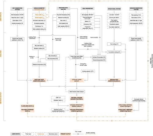
As observed, inputs are organized into six main interrelated groups: geometry, climate, soil conditions, structural system selection, sky dissipation system, and ground dissipation system. The tools used at each step, either analytical models or simulation software, are also highlighted alongside the intermediary outputs necessary to obtain the final metrics. Additionally, the framework presents a feedback loop between selected outputs and inputs, allowing for an iterative evaluation (and potential optimization) of urban geometries in a fast and streamlined manner. This sampling process is conducted using the Design Space Exploration (DSE) plugin developed by the Digital Structures group at MIT (Brown, Jusiega, and Mueller Citation2020).
4. Results
The following section presents two main application scenarios for the proposed multi-domain methodology: (1) iterative sampling across design options to identify correlations between urban geometry and the different performance metrics and (2) the in-depth analysis of the heat dissipation potential of selected geometries on a month-by-month basis.
4.1. Design sampling
A combination of 135 design options is sampled across each of the mentioned climates (accounting for the UHI effect) using the grid sampling tool included in mentioned DSE plugin. Up to six different metrics are recorded to holistically evaluate the performance of each design: cooling operational and structural embodied carbon (kgCO2e/m2), heat dissipated through the night sky and the ground (kWh/m2year), floor area ratio (FAR) and plan area density (λp). The two geometric variables Xtotal and n (Figure ) are sampled within the following bounds (Table ).
Figure 7. The structural embodied carbon increases linearly with FAR, as result of the higher foundation area Af.
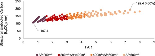
Table 3. Variables’ bounds.
The sampling results reveal how the structural embodied carbon increases with FAR due to the higher foundation area Af in taller buildings and, to a lesser extent, the larger column sections on lower floors. The contribution of these two elements to the building's overall structural carbon budget results in an 80% variability in the sampled values, from 107.1 kgCO2e/m2 to 192.4 kgCO2e/m2.
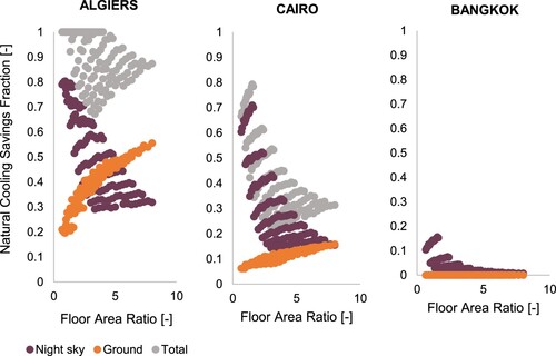
Figure shows the NCSF factor (the fraction of cooling load met by each heat sink) for all considered designs. As anticipated, the analyzed low-energy technologies are most effective in dry climates (lower Tsink_sky) with higher seasonal temperature fluctuations (lower Tsink_ground). Geothermal cooling, when available, increases with FAR in Algiers and Cairo due to the larger foundation areas. On the contrary, the night sky NCSF reduces with FAR for all climates: as neighbourhoods become denser, the ratio of roof area to floor area decreases. Overall, the cooling potential through the sky is predominant for most cases, reaching values of up to 0.7 in Cairo and 0.15 in Bangkok. Only for designs in Algiers with FAR>5.5, is it more efficient to dissipate heat through the ground than the night sky.
Figure 8. The night sky cooling NCSF decreases with FAR for all climates given the lower ceiling-to-floor ratio. In constrast, the ground cooling NCSF increases with higher urban densities thanks to the larger foundation areas.
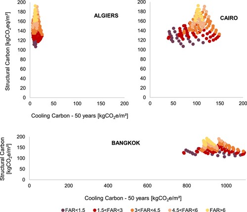
These sampling results display the significant sensitivity of the neighbourhoods’ heat dissipation potential to their urban geometry and weather conditions. Figure condenses them into a single operational carbon value for a 50-year building lifespan and compares the results to the structural embodied carbon computed in parallel. As observed, in climates where the heat dissipation strategies are most effective (Algiers, Cairo), the relative impact of the embodied carbon is much more prominent than in hot-humid locations such as Bangkok, in which NCSF values are much lower. In absolute terms, the 50-year cooling carbon can become up to seven times higher in Bangkok (1087 kgCO2eq/m2) compared to Cairo (148 kgCO2eq/m2).
Figure 9. For a given climate, the structural-to-cooling carbon ratio largely depends on the building's cooling loads and ability to dissipate heat. In humid climates like Bangkok's, the operational carbon predominates due to the low performance of the selected systems and high loads, while in hot desertic climates (Algiers, Cairo), the embodied carbon is comparatively larger.
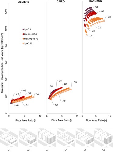
Finally, Figure synthesizes the carbon calculations into a single cumulative value for the structural and cooling emissions as a function of FAR. These plots highlight the expected correlation between FAR and environmental impact but also reveal an insightful clustering of the data as a function of the plan area density λp. The mentioned tradeoff between FAR and carbon emissions improves as λp increases, meaning that it is possible to reach a higher built floor area for the same kgCO2e value (or decrease the carbon impact for a given FAR value). Buildings with larger widths (higher λp) permit increasing FAR while maintaining the same roof-to-floor area ratio, not compromising the cooling capacity of the night sky radiator. However, reducing the urban footprint can be preferable from other perspectives not covered in this paper (access to green open spaces, for example), thus the need to display the full spectrum of sub-optima results for any given λp value.
Figure 10. As expected, the designs’ carbon impact (combining structural and cooling carbon) increases with FAR. This tradeoff varies with λp, showing lower carbon emissions for equivalent FAR as the plan area density λp increases.
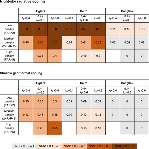
The findings of this first study are summarized in Figure , providing design guidelines for each of the three analyzed climates across different FAR and plan area density (λp) ranges. The upper table shows the Natural Cooling Savings Fraction (NCSF) achieved by the night-sky heat dissipation system, while the lower refers to the ground heat dissipation system. As identified in the previous pages, higher λp values favour the performance of the roof radiator, while denser urban designs (higher FAR) lead to improved ground dissipation.
Figure 11. Summary of Natural Cooling Savings Fraction (NCSF) values for each heat dissipation system across FAR and plan area density (λp). The values for each table are not additive, as they may refere to different designs.
4.2. Urban heat island assessment
The presented workflow also provides the opportunity to analyze in detail the interactions between the available heat sinks and the urban microclimate. Design G2 is selected for this brief study, a neighbourhood geometry with values of FAR = 4 and λp = 0.8. Figure presents the effective temperature for both urban sinks (Teff_ground and Teff_sky) in Cairo, comparing the original rural weather file with the morphing captured by the UWG model. As observed, the UHI effect increases both effective temperatures, with a uniform 0.7°C increment in Teff_ground due to the warmer soil surface and higher peak values for Teff_sky. This circumstance reduces the ΔT between the heat sink and the exchanger's inlet temperature (set here as 26.5°C), which compromises the availability of the heat sinks during some periods of the year.
Figure 12. Predicted mean daily values for ground (2 m depth) and sky effective temperatures in Cairo's climate. The UHI values correspond to the urban geometry G2.
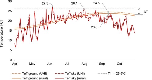
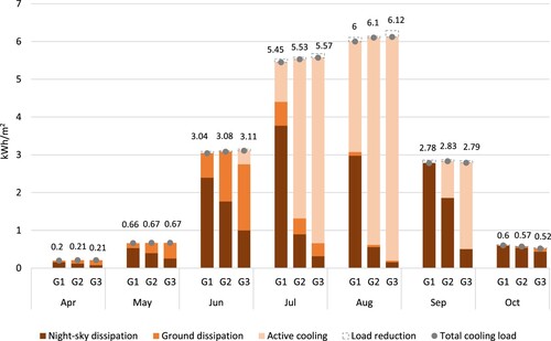
Figure further expands this analysis by evaluating the monthly cooling loads and total energy dissipation across three different geometries (G1, G2, and G3) with equal building plan area density (0.8) and varying FAR (1.6, 4, and 8, respectively). As expected, increasing the density of a given urban design has a double-fold negative impact: cooling loads rise as a result of the added anthropogenic heat fluxes, while the rate of cooling demand covered by low-energy systems decreases due to the lower ratio of dissipation surface relative to the floor area. Despite this, the combined ground and night sky cooling significantly reduces the buildings’ dependence on conventional air conditioning systems across all designs, especially during the shoulder seasons. The heat dissipation systems cover 100% of the cooling demand for all geometries during April, May, June, and October, with the exception of G3 during June (covering 88%). This analysis also evidences the reduction in the availability of the ground as a heat sink after the month of July due to the ground's thermal lag identified in the previous plot.
Figure 13. Cooling energy breakdowwn (active cooling, night-sky, and ground dissipation) across three different urban designs (G1, G2, and G3) with equal building plan area density (0.8) and increasing FAR (1.6, 4, and 8, respectively). As observed, the heat dissipations systems cover 100% of the cooling demand during the shoulder seasons for all geometries and a significant percentage during summer months for designs with lower FAR such as G1 (80% in July and 51% in August). Additionally, the total cooling load decreases by 1-3% compared to the baseline thanks to the reduction of heat released into the urban canyon.
The dissipation of heat through alternative sinks presents the added benefit of reducing the anthropogenic heat fluxes released into the urban canyon, which in turn decreases the urban temperatures (a positive feedback described in more detail in section 3.3.3). Figure includes the impact of this UHI mitigation process on the monthly cooling loads of the three designs. Cooling loads are, on average, 1% lower during the summer months and can be up to 3% lower for geometries with higher FAR. This phenomenon positively impacts the urban microclimate, decreasing the number of outdoor thermal discomfort hours, measured as values above 26°C on the universal thermal comfort index (UTCI), by 1% on average.
5. Conclusions
5.1. Summary of contributions
The design of heat-resilient and resource-efficient cities is a pressing matter, requiring novel simulation tools that simultaneously account for buildings’ embodied and operational impact as highlighted by recent lifecycle studies on residential neighbourhoods (Gauch et al. Citation2023). The presented paper contributes to this ongoing research effort through an innovative, multi-domain simulation workflow that focuses on the design of low-cost, integrated heat sinks at an urban level. Such systems have the potential to provide low-energy cooling with a reduced material impact, demanding accessible and holistic design tools that help uncover systems-level optimization opportunities. Methodologically, the contribution of this research mainly lies in three aspects: (1) the implementation of a flexible and computationally fast parametric design framework (combining analytical models and numerical simulations) tailored for early-stage decision processes, (2) the consideration of the building-city interactions between the heat sinks performance and the urban morphology (3) the evaluation of the building structural material budget and its environmental impact relative to the operational cooling carbon.
The results presented in section 4 exemplify the method's integrated approach and suitability for identifying synergic solutions. Two well-studied and available heat dissipation systems were analyzed (shallow geothermal and night sky cooling) for a hypothetical case study, analyzing their performance across three hot climates and two geometric variables (number of floors n and block width Xtotal). The parametric study revealed how the night sky cooling performance decreased with FAR for all climates, contrarily to the ground cooling, which increased with higher urban densities thanks to the larger foundation areas. In the case of Algiers (a Mediterranean climate with hot summer), a natural cooling saving fraction NCSF = 1 was achieved for FAR<4.5, revealing designs exclusively conditioned by the heat dissipation systems. Comparison of the structural and cooling carbon revealed that operational emissions predominated in Bangkok, a humid climate with high cooling loads and low NCSF, while embodied emissions prevailed in Algiers and Cairo as a result of the higher NCSF.
Similarly, the urban heat island assessment highlighted the multi-scale advantages of heat dissipation strategies. In alignment with recent studies on the urban heat mitigation benefits of energy efficiency measures in buildings (Baniassadi et al. Citation2022), the leverage of urban heat sinks has a combined positive effect on the buildings’ energy use (lowering the dependence on active cooling systems) and urban temperatures (reducing the heat released into the urban canyon). The analyzed case study showed that, together with the low-energy cooling provided, the heat sinks provide a 1% reduction in the outdoor discomfort hours (UTCI>26), which lowered the buildings’ cooling demand by 1%. These percentages could potentially be larger for more energy-intensive building uses.
5.2. Limitations and future work
The proposed multi-domain workflow presents both limitations and opportunities that should be tackled in future work by either extending this framework or contributing to existing urban design tools. First, the method could be expanded to a broader array of heat dissipation technologies by calculating the corresponding effective temperatures Teff and overall heat transfer U values. These include alternative versions of the studied systems for example, recent advances in low-cost daytime radiative cooling (Zhai et al. Citation2017) that can be integrated in naturally ventilated buildings (Fortin et al. Citation2023) or other integrated heat sinks not explored in this work, such as evaporative cooling. Similarly, the presented framework is, in principle, applicable to existing cities and could thus be further developed in the context of building retrofitting and climate future-proofing.
Concerning the limitations, it is important to keep in mind the assumptions made by the chosen analytical models (see sections 3.3.1. and 3.3.2) and their associated margin of error. More importantly, future versions of this method should include the consideration of seasonal regeneration strategies for the ground cooling (extracting heat for space heating during winter, or producing domestic hot water, among others) and guidelines on the adequate spacing between integrated HGHE at a neighbourhood scale. From an implementation point of view, embedding water pipes inside structural elements comes with an associated leakage risk that can become complex to repair. This problem is commonly overcome through a series of safety measures, such as over-pressurizing the circuit before casting the concrete or creating registration points, as well as using appropriate piping materials for instance, high-density polyethylene (Brandl Citation2006). Finally, a more extensive parametric study should consider the interaction between multiple urban design variables and adding socio-architectural evaluation parameters (Bardhan et al. Citation2018). While the results presented here show that buildings with higher plan area density (λp) tend to perform better from a heat dissipation perspective, neighbourhoods with lower λp offer space for larger green areas, providing an essential infrastructure for urban heat mitigation and social gathering. Future versions of this method will hopefully provide solutions to these and many other multi-domain design challenges that lead toward a more sustainable and resilient urban environment.
As the need for cooling increases globally, a societal shift is needed from conventional air conditioning systems to alternative heat dissipation strategies that are affordable and that do not warm up our cities further. This paper has presented a method to design and simulate two well-studied systems integrated within structural components, demonstrating the possibility of leveraging the ground as a seasonal sink and the universe as an infinite sink to cool cities globally, especially those in temperate and hot-dry climates.
Disclosure statement
No potential conflict of interest was reported by the author(s).
Data availability statement
The data that support the findings of this study are available from the corresponding author upon reasonable request.
Additional information
Funding
References
- “The Future of Cooling,” IEA, Paris, 2018. [Online]. Available: https://www.iea.org/reports/the-future-of-cooling.
- “The future we don’t want. How climate change could impact the world’s greatest cities.,” UCCRN Technical Report, 2018.
- Statistical Review of World Energy 2022, p. 60.
- World urbanization prospects: the 2018 revision. 2019. New York: United Nations.
- Allwood, J. M., and J. M. Cullen. 2015. Sustainable Materials Without the Hot Air: Making Buildings, Vehicles & Products Efficiently and with Less new Material. Cambridge: UIT Cambridge Ltd.
- Alvarez, S., I. R. Maestre, and R. Velazquez. Nov. 1997. “Design Methodology and Cooling Potential of the Environmental Heat Sinks.” International Journal of Solar Energy 19 (1–3): 179–197. https://doi.org/10.1080/01425919708914336.
- Argiriou, A., M. Santamouris, and D. N. Assimakopoulos. Aug. 1994. “Assessment of the Radiative Cooling Potential of a Collector Using Hourly Weather Data.” Energy 19 (8): 879–888. https://doi.org/10.1016/0360-5442(94)90040-X.
- Arroyo Portero, J. C., R. Sánchez Fernández, A. Romero Ballesteros, M. G. Romana García, G. Corres Peiretti, and G. García-Rosales. 2009. Números Gordos en el Proyecto de Estructuras. Madrid: Cinter Divulgación Técnica.
- Baniassadi, A., J. Heusinger, N. Meili, P. Izaga Gonzalez, and H. Samuelson. Dec. 2022. “Urban Heat Mitigation Through Improved Building Energy Efficiency.” Energy and Climate Change 3: 100078. https://doi.org/10.1016/j.egycc.2022.100078.
- Bardhan, R., R. Debnath, J. Malik, and A. Sarkar. Aug. 2018. “Low-Income Housing Layouts Under Socio-Architectural Complexities: A Parametric Study for Sustainable Slum Rehabilitation.” Sustainable Cities and Society 41: 126–138. https://doi.org/10.1016/j.scs.2018.04.038.
- Bayer, P., G. Attard, P. Blum, and K. Menberg. May 2019. “The Geothermal Potential of Cities.” Renewable and Sustainable Energy Reviews 106: 17–30. https://doi.org/10.1016/j.rser.2019.02.019.
- Beck, H. E., N. E. Zimmermann, T. R. McVicar, N. Vergopolan, A. Berg, and E. F. Wood. Dec. 2018. “Present and Future Köppen-Geiger Climate Classification Maps at 1-km Resolution.” Scientific Data 5 (1): 180214. https://doi.org/10.1038/sdata.2018.214.
- Berdhal, P., and M. Martin. 1984. “Emissivity of Clear Skies.” Solar Energy 32 (5): 663–664. https://doi.org/10.1016/0038-092X(84)90144-0
- Brandl, H. Mar. 2006. “Energy Foundations and Other Thermo-Active Ground Structures.” Géotechnique 56 (2): 81–122. https://doi.org/10.1680/geot.2006.56.2.81.
- Brearley, J. 2022. “Taming Torridity: New Housing Forms for Heat Resilience,” Massachusetts Institute of Technology, [Online]. Available: https://dspace.mit.edu/handle/1721.1/144536.
- Brown, N. C., V. Jusiega, and C. T. Mueller. Oct. 2020. “Implementing Data-Driven Parametric Building Design with a Flexible Toolbox.” Automation in Construction 118: 103252. https://doi.org/10.1016/j.autcon.2020.103252
- Bueno, B., L. Norford, J. Hidalgo, and G. Pigeon. Jul. 2013. “The Urban Weather Generator.” Journal of Building Performance Simulation 6 (4): 269–281. https://doi.org/10.1080/19401493.2012.718797.
- Bureau of Indian Standards. 2000. “IS 456: Plain and Reinforced Concrete - Code of Practice,”.
- Charan, T., C. Mackey, A. Irani, B. Polly, S. Ray, K. Fleming, R. El Kontar, et al. Sep. 2021. “Integration of Open-Source URBANopt and Dragonfly Energy Modeling Capabilities Into Practitioner Workflows for District-Scale Planning and Design.” Energies 14 (18): 5931. https://doi.org/10.3390/en14185931.
- Clark, E., and P. Berdahl. 1981. “Radiative Cooling: Resource and Applications.” Sponsored and Developed by US Department of Energy Pub 375: 219.
- D’Amico, B., and F. Pomponi. Sep. 2020. “On Mass Quantities of Gravity Frames in Building Structures.” Journal of Building Engineering 31: 101426. https://doi.org/10.1016/j.jobe.2020.101426.
- Dimoudi, A., and A. Androutsopoulos. Aug. 2006. “The Cooling Performance of a Radiator Based Roof Component.” Solar Energy 80 (8): 1039–1047. https://doi.org/10.1016/j.solener.2005.06.017.
- Eicker, U., and A. Dalibard. Jul. 2011. “Photovoltaic–Thermal Collectors for Night Radiative Cooling of Buildings.” Solar Energy 85 (7): 1322–1335. https://doi.org/10.1016/j.solener.2011.03.015.
- Eisenbarth, C., W. Haase, L. Blandini, and W. Sobek. Jun. 2022. “Potentials of Hydroactive Lightweight Façades for Urban Climate Resilience.” Civil Engineering Design 4 (1–3): 14–24. https://doi.org/10.1002/cend.202200003.
- Emmanuel, W., and K. Jérôme. 2015. “A verification of CitySim results using the BESTEST and monitored consumption values”. In Proceedings of the 2nd Building Simulation Applications conference, no. CONF, pp. 215-222. Bozen-Bolzano University Press.
- Fonseca, J. A., and A. Schlueter. Mar. 2015. “Integrated Model for Characterization of Spatiotemporal Building Energy Consumption Patterns in Neighborhoods and City Districts.” Applied Energy 142: 247–265. https://doi.org/10.1016/j.apenergy.2014.12.068.
- Fortin, R., J. Mandal, A. P. Raman, and S. Craig. 2023. “Passive Radiative Cooling to sub-Ambient Temperatures Inside Naturally Ventilated Buildings.” Cell Reports Physical Science 4 (9): 101570. doi:10.1016/j.xcrp.2023.101570.
- Gascón Alvarez, E., N. L. Stamler, C. T. Mueller, and L. K. Norford. 2022. “Shape Optimization of Chilled Concrete Ceilings – Reduced Embodied Carbon and Enhanced Operational Performance.” Building and Environment 221.
- Gauch, H. L., C. F. Dunant, W. Hawkins, and A. Cabrera Serrenho. Mar. 2023. “What Really Matters in Multi-Storey Building Design? A Simultaneous Sensitivity Study of Embodied Carbon, Construction Cost, and Operational Energy.” Applied Energy 333: 120585. https://doi.org/10.1016/j.apenergy.2022.120585.
- Guerrero Delgado, Mc., J. Sánchez Ramos, and S. Álvarez Domínguez. Dec. 2020. “Using the sky as Heat Sink: Climatic Applicability of Night-sky Based Natural Cooling Techniques in Europe.” Energy Conversion and Management 225: 113424. https://doi.org/10.1016/j.enconman.2020.113424.
- Hammond, G., and C. Jones. 2019. “Inventory of Carbon and Energy (ICE),” Version 3.
- Hammond, G. P., and C. I. Jones. May 2008. “Embodied Energy and Carbon in Construction Materials.” Proceedings of the Institution of Civil Engineers - Energy 161 (2): 87–98. https://doi.org/10.1680/ener.2008.161.2.87.
- Hawkins, W., J. Orr, T. Ibell, and P. Shepherd. Mar. 2020. “A Design Methodology to Reduce the Embodied Carbon of Concrete Buildings Using Thin-Shell Floors.” Engineering Structures 207: 110195. https://doi.org/10.1016/j.engstruct.2020.110195.
- Hosseinzadeh, E., and H. Taherian. Nov. 2012. “An Experimental and Analytical Study of a Radiative Cooling System with Unglazed Flat Plate Collectors.” International Journal of Green Energy 9 (8): 766–779. https://doi.org/10.1080/15435075.2011.641189.
- International Code Council. Oct. 2020. “2021 International Building Code (IBC): Chapter 18 Soils and Foundations,” International Code Council, Inc.
- International Organization for Standardization. 2017. Energy Performance of Buildings-Energy Needs for Heating and Cooling, Internal Temperatures and Sensible and Latent Heat Loads-Part 1: Calculation Procedures. Vol. 52016-1.
- Ismail, M., and C. Mueller. Nov. 2021. “Minimizing Embodied Energy of Reinforced Concrete Floor Systems in Developing Countries Through Shape Optimization.” Engineering Structures 246: 112955. https://doi.org/10.1016/j.engstruct.2021.112955.
- Ji, S., B. Lee, and M. Y. Yi. Nov. 2021. “Building Life-Span Prediction for Life Cycle Assessment and Life Cycle Cost Using Machine Learning: A big Data Approach.” Building and Environment 205: 108267. https://doi.org/10.1016/j.buildenv.2021.108267.
- Kaethner, S. C., and J. A. Burridge. 2012. “Embodied CO2 of structural frames,” p. 8.
- Krarti, M., and J. F. Kreider. 1996. “Analytical Model for Heat Transfer in an Underground air Tunnel.” Energy Conversion and Management 37 (10): 1561–1574. https://doi.org/10.1016/0196-8904(95)00208-1
- Krarti, M., C. Lopez-Alonzo, D. E. Claridge, and J. F. Kreider. May 1995. “Analytical Model to Predict Annual Soil Surface Temperature Variation.” Journal of Solar Energy Engineering 117 (2): 91–99. https://doi.org/10.1115/1.2870881.
- Kurian, N. P. 2004. Design of Foundation Systems: Principles and Practices, 3rd ed. Oxford: Alpha Science International Ltd..
- Lee, K. H., and R. K. Strand. 2006. “Implementation of an Earth Tube System Into Energyplus Program”. In Proceedings of the SimBuild 2006 Conference, Boston MA, USA.
- López, D. L., D. Veenendaal, M. Akbarzadeh, and P. Block. 2014. “Prototype of an Ultra-Thin, Concrete Vaulted Floor System,” In Proceedings of IASS annual symposia (Vol. 2014, No. 15, pp. 1-8). International Association for Shell and Spatial Structures (IASS).
- Mauree, D., E. Naboni, S. Coccolo, A. T. D. Perera, V. M. Nik, and J.-L. Scartezzini. Sep. 2019. “A Review of Assessment Methods for the Urban Environment and its Energy Sustainability to Guarantee Climate Adaptation of Future Cities.” Renewable and Sustainable Energy Reviews 112: 733–746. https://doi.org/10.1016/j.rser.2019.06.005.
- Meir, M. G., J. B. Rekstad, and O. M. LØvvik. 2002. “A Study of a Polymer-Based Radiative Cooling System.” Solar Energy 73 (6): 403–417. https://doi.org/10.1016/S0038-092X(03)00019-7
- Miglani, S., K. Orehounig, and J. Carmeliet. Jan. 2018. “A Methodology to Calculate Long-Term Shallow Geothermal Energy Potential for an Urban Neighbourhood.” Energy and Buildings 159: 462–473. https://doi.org/10.1016/j.enbuild.2017.10.100.
- Mihalakakou, G., A. Ferrante, and J. O. Lewis. 1998. “The Cooling Potential of a Metallic Nocturnal Radiator.” Energy and Buildings 28 (3): 251–256. doi:10.1016/S0378-7788(98)00006-1.
- Mokhtari, R., G. Ulpiani, and R. Ghasempour. Jul. 2022. “The Cooling Station: Combining Hydronic Radiant Cooling and Daytime Radiative Cooling for Urban Shelters.” Applied Thermal Engineering 211: 118493. https://doi.org/10.1016/j.applthermaleng.2022.118493.
- Moncaster, A. M., and J.-Y. Song. 2012. “A Comparative Review of Existing Data and Methodologies for Calculating Embodied Energy and Carbon of Buildings.” International Journal of Sustainable Building Technology and Urban Development 3 (1), doi:10.1080/2093761X.2012.673915.
- Naili, N., M. Hazami, I. Attar, and A. Farhat. Nov. 2013. “In-field Performance Analysis of Ground Source Cooling System with Horizontal Ground Heat Exchanger in Tunisia.” Energy 61: 319–331. https://doi.org/10.1016/j.energy.2013.08.054.
- Nam, Y., and H.-B. Chae. Aug. 2014. “Numerical Simulation for the Optimum Design of Ground Source Heat Pump System Using Building Foundation as Horizontal Heat Exchanger.” Energy 73: 933–942. https://doi.org/10.1016/j.energy.2014.06.108.
- Nault, E., C. Waibel, J. Carmeliet, and M. Andersen. Jun. 2018. “Development and Test Application of the UrbanSOLve Decision-Support Prototype for Early-Stage Neighborhood Design.” Building and Environment 137: 58–72. https://doi.org/10.1016/j.buildenv.2018.03.033.
- Oke, T. R., G. Mills, A. Christen, and J. A. Voogt. 2017. Urban Climates. Cambridge: Cambridge University Press.
- Reinhart, C. F., T. Dogan, J. A. Jakubiec, T. Rakha, and A. Sang. 2013. “UMI - An Urban Simulation Environment for Building Energy Use, Daylighting and Walkability,” Presented at the Proceedings of BS 2013: 13th Conference of the International Building Performance Simulation Association, pp. 476–483. [Online]. Available: https://www.scopus.com/inward/record.uri?eid=2-s2.0-84886703233&partnerID=40&md5=191677333e976af7ca6b348a8bb05191.
- Sadeghipour Roudsari, M., and M. Pak. Aug 2013. “Ladybug: A Parametric Environmental Plugin for Grasshopper to Help Designers Create an Environmentally-Conscious Design,” in Proceedings of the 13th International IBPSA Conference, Lyon, France.
- “The International Building Code”. 2015. ICC, Mar. 20, 2015. https://www.iccsafe.org/products-and-services/i-codes/2018-i-codes/ibc/ (accessed Nov. 29, 2019).
- Timmer, A. Jan. 2021. “Building Integrated Evaporative Cooling Utilizing Pervious Concrete.” Technology Architecture Design 5 (1): 73–81. https://doi.org/10.1080/24751448.2021.1863675.
- Walch, A., X. Li, J. Chambers, N. Mohajeri, S. Yilmaz, M. Patel, and J. L. Scartezzini. Apr. 2022. “Shallow Geothermal Energy Potential for Heating and Cooling of Buildings with Regeneration Under Climate Change Scenarios.” Energy 244: 123086. https://doi.org/10.1016/j.energy.2021.123086.
- Weber, R. E., C. Mueller, and C. Reinhart. 2020. “Generative Structural Design for Embodied Carbon Estimation,” In Proceedings of IASS Annual Symposia (Vol. 2020, No. 8, pp. 1-12). International Association for Shell and Spatial Structures (IASS).
- Zhai, Y., Y. Ma, S. N. David, D. Zhao, R. Lou, G. Tan, R. Yang, and X. Yin. Mar. 2017. “Scalable-manufactured Randomized Glass-Polymer Hybrid Metamaterial for Daytime Radiative Cooling.” Science 355 (6329): 1062–1066. https://doi.org/10.1126/science.aai7899.
- Zhao, D., A. Aili, X. Yin, G. Tan, and R. Yang. Nov. 2019. “Roof-integrated Radiative air-Cooling System to Achieve Cooler Attic for Building Energy Saving.” Energy and Buildings 203: 109453. https://doi.org/10.1016/j.enbuild.2019.109453.
- Zhao, D., C. E. Martini, S. Jiang, Y. Ma, Y. Zhai, G. Tan, X. Yin, and R. Yang. Nov. 2017. “Development of a Single-Phase Thermosiphon for Cold Collection and Storage of Radiative Cooling.” Applied Energy 205: 1260–1269. https://doi.org/10.1016/j.apenergy.2017.08.057.