
Abstract
This work proposes an automated workflow using digital twinning for multi-domain environmental performance analysis of urban developments. Digital twins can potentially provide a common basis for multi-domain simulations and help overcome data availability and interoperability issues. The proposed workflow consists of five steps: (1) creating a procedural urban 3D model, (2) generating design alternatives parametrically, (3) exporting the context and each design alternative to each simulation tool, (4) running simulations for wind comfort, energy demand, and noise for each design alternative, and (5) combining and visualizing the simulation results using the digital twin. The workflow was applied to a neighbourhood in Sweden, the resultsreveal significant reduction in manual work when applying multiple simulation software for different domains. This is one step forward in streamlining the workflow for urban analysis, crucial for multi-domain optimization. In the future, further domains and simulation tools can be added to the workflow.
1. Introduction
According to UN Habitat, cities consume 78% of the world's energy and emit over 60% of greenhouse gas (GHG) emissions, which are projected to increase with rapid urbanization (Ahmadian et al. Citation2021). In response, stakeholders involved in urban development must increase their efforts in climate protection and adaptation (United Nations Climate Change Citation2016), including reducing GHG emissions, building resilience, and adapting to climate events (Loibl et al. Citation2021; Tollin et al. Citation2017). With 55% of the world's population currently living in cities (United Nations Citation2019) and projected to reach 81% in developed countries by 2050 (United Nations Citation2018), it is necessary to anticipate the space and infrastructure needs and optimize the environmental performance of the buildings. This requires a deeper understanding of the complex interaction of parameters, where urban shape and density in combination with for example temperature (Dorer et al. Citation2013; Yin et al. Citation2018), wind (Javanroodi and Nik Citation2019; Merlier et al. Citation2018), and noise (EEA Citation2020; Forssén et al. Citation2022), can influence the performance of the urban environment.
1.1. Problem statement
The complex urban interactions make it essential to simulate and assess different scenarios of densification to exploit potential benefits while limiting negative impacts (Loibl et al. Citation2021). The number of urban analysis tools is wide and growing, covering more and more types of analysis (Sola et al. Citation2018); from GIS, urban climate to Urban-Scale Energy Modelling (USEM), which can include different domains. In the development of urban analysis, a number of aspects have to be taken into account, which may involve a large number of fields of study, as well as tools, requiring specific knowledge and complex calculations (Lyden, Pepper, and Tuohy Citation2018). The investment in such studies can be high. However, various stakeholders, such as municipalities, housing authorities or energy distribution companies have realized the great potential of these tools but have been slow to adopt them (Agugiaro et al. Citation2018).
One of the most complex areas of environmental assessment is the use of computational fluid dynamics (CFD) for wind simulations, where there are several barriers limiting their mass application, including the specific knowledge required for their application (Kaijima et al. Citation2013). Similar is the case in urban energy planning, as knowledge and understanding of the urban space, its infrastructure and underground characteristics are necessary to carry out a simulation to analyse the energy demand and available energy resources (Agugiaro et al. Citation2018). Furthermore, acoustic analysis is key in the development of holistic urban planning. Recent EU projects have demonstrated the benefits of introducing acoustics into the urban planning process. Their results have shown that a thorough understanding of acoustics is necessary to assess the effects of noise control measures and control the soundscape (Alves et al. Citation2015). Studies focusing on the interactions between these factors, such as energy demand, noise, and wind comfort, are scarce and therefore, more research is needed (Mauree et al. Citation2019).
Therefore, there must be an effective exchange of harmonized and high-quality data from a variety of sources between different urban actors, which ultimately feed into different analysis tools (Nouvel et al. Citation2015). Here, urban digital twins could provide a solution. ‘Digital twin’ was introduced as a concept in the manufacturing industry in the early 2000s (Grieves Citation2014). Despite having been introduced a couple of decades ago there is still no standardized definition, as it changes according to the discipline (Caprari Citation2022), but most definitions now agree that a digital twin is a model of a physical system that mirrors the physical system in real time and enables analysis and prediction of the physical system (de Wilde Citation2023; Logg and Naserentin Citation2022).
Nevertheless, fully realized digital twins are seldomly encountered in practice. The challenge lies in establishing a seamless real-time link between the digital twin and its physical counterpart. This connection demands a bi-directional coupling: not only should the digital model continuously receive updates from the physical system, but the physical system should also be influenced by the digital model, especially when the latter is employed for managerial or control purposes. Contrarily, many entities termed as ‘digital twins’ often display only unidirectional real-time coupling – from the physical to the digital, but not vice versa. In some instances, rather than an automated data flow from the physical system to the digital model, data acquisition and preparation are done manually.
Kritzinger et al. (Citation2018) recently elucidated this scenario by categorizing digital twinning into three distinct levels: digital model, digital shadow, and digital twin. The digital model lacks an automated data exchange between the digital and physical systems. The digital shadow, meanwhile, offers one-way automated data flow, typically involving sensor data from the physical entity to the digital model. The digital twin stands out with its bi-directional automated data exchange, enabling not only analysis but also active management and control of the physical system.
In our ongoing research, we employ the term ‘digital twinning’ as a backdrop for examining multi-domain simulation workflows. Our ultimate goal is the integration of these workflows into a comprehensive digital twin system. However, since our current simulations do not directly control the physical entity (the city), they don't qualify as a digital twin by the strictest definition. Rather, the workflows we introduce fall under the realm of a digital shadow of the actual city, given that certain data points, such as weather information, are automatically sourced from online platforms.
The Digital Twin City Centre (DTCC)Footnote1 is an initiative aiming at establishing the Digital Twin City concept as foundation for digital planning, design, construction, and management of sustainable, intelligent, and liveable cities and regions throughout Sweden. Within the DTCC, an open platform is developed to support stakeholders such as municipalities in developing their urban digital twin. With the digital twin, it becomes possible to connect scenarios, with past, present and projected information (Shahat, Hyun, and Yeom Citation2021), test designs, plan modifications and improve the management and operation of the city. For instance, digital twins of cities already started to be applied in different areas connected to urban planning, architecture, earthquakes prediction, oil resistance, disaster management, etc. (Ketzler et al. Citation2020). However, only a handful of urban digital twins exist (Ketzler et al. Citation2020; Saeed et al. Citation2022) and even in those environments, obtaining results on the micro-climate scale can be cumbersome due to data availability and operability issues (Caprari Citation2022; Lehtola et al. Citation2022; Tzachor et al. Citation2022).
1.2. Goal statement
The aim of this article is to develop a streamlined and harmonized workflow to allow for environmental performance optimization of urban design. Therefore, the main research question is: How can digital twinning be used to facilitate multi-domain urban environmental analysis for design optimisation?
The developed method will be applied to a case study in Sweden using three main domains for simulation: Wind, energy, and noise. These environmental variables have been identified in the current literature as key factors. Noise ranks among the environmental factors with highest disease burden (Klingberg et al. Citation2017; Pont et al. Citation2019), wind can lead to high discomfort particularly in Nordic countries and plays a significant role in the urban microclimate (Brozovsky, Radivojevic, and Simonsen Citation2022; Eliasson et al. Citation2007; Javanroodi and Nik Citation2019; Venter, Krog, and Barton Citation2020). Meanwhile energy consumption is vital for developing sustainable cities and reducing their energy consumption. Additionally, other aspects such as daylight, air pollution, heat, are of importance as well and could potentially be added in the future.
The study relies on simulations to evaluate the current state and various scenarios. While not all selected domains are interconnected, wind and energy are. To leverage this interconnection and produce more reliable results, we have explored the technique of coupling these two simulations. This allows the simulations to exchange their results within a novel simulation workflow, enabling automated analysis of any part of the city's digital twin. In this particular case, we have additionally examined various variations in the existing context of a Gothenburg area.
Seven different hypothetical design alternatives within an existing urban neighbourhood are compared. The use of digital twinning will be evaluated towards two main aspects: (a) providing the 3D models and semantic data needed for the different simulation engines, and (b) visualizing the simulation in a harmonized way for decision making.
2. Method
The method describes the development of the multi-domain simulation workflow based on digital twinning. Then details about the simulation procedure and performance indicators are described before the case study is introduced. All procedural workflows developed in this project are intended to be scalable and adaptable to other cities in Sweden and worldwide.
2.1. Workflow development based on digital twinning
The proposed workflow is based on five steps: (1) 3D model generation of context; (2) generation of design alternatives to be tested; (3) mesh and surface model generation for the different simulation engines to ensure interoperability; (4) simulations; and (5) combining, visualizing, and assessing results. An overview of the workflow can be seen in Figure .
Figure 1. Outline of the methodology used in the study.
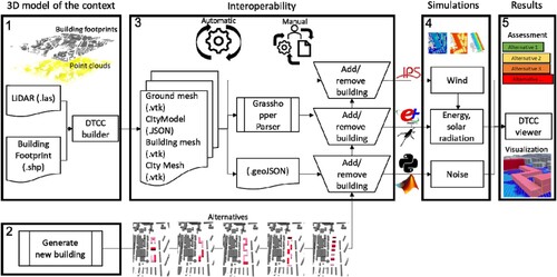
Each step of the workflow is detailed below:
3D model generation of context
For generating the geometries used in the various simulations, we rely on data provided by the Swedish National Land Survey (Lantmäteriet). This data consists of building footprints (ShapeFiles –.shp) and LiDaR point clouds (LASer –.las). The raw data is then processed by DTCC Builder (DTCC Builder Citation2022; Naserentin and Logg Citation2022) to generate both two separate building and terrain triangle meshes and a combined water-tight triangle mesh (.vtk) for the buildings and terrain. Furthermore, a semantic model that represents the building footprints, ground height and building height (JavaScript Object Notation –.json) at Level of Detail 1 (LoD-1 based on the concept of CityGML (Biljecki, Ledoux, and Stoter Citation2016)) is generated.
Generation of design alternatives to be tested
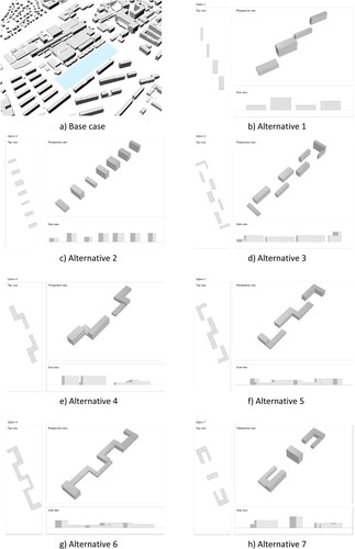
The design alternatives mainly serve the purpose to test the workflow and show the potential of the automatization. To prevent any potential bias in the results, the design of building alternatives was randomized. The alternatives meet the following requirements: the total volume of each alternative has to be the same, in this case 5500 m3; (2) the maximum number of floors that can be reached in each block is seven levels; (3) the layout of the blocks of each alternative has to be realistic or represent a common typology of building block layout.
Using seven different common building block layout topologies, the randomization focused on the building blocks’ height and width maintaining the requirements mentioned above. Height, width and layout affect the shadows that buildings cast on each other (Mirashk-Daghiyan et al. Citation2022; Wang, Liu, and Zhang Citation2021), wind flow patterns (Du, Mak, and Tang Citation2018; Mittal, Sharma, and Gairola Citation2018), and noise propagation(Klingberg et al. Citation2017; Lee and Kang Citation2015; Pont et al. Citation2019). These factors can impact the energy performance of the existing buildings, the wind comfort and the urban noise levels.
Input generation for the different simulation engines
Interoperability between file formats and levels of detail play an important role. In addition to the file formats mentioned above, we make use of custom file parsers for the noise simulation to translate between the DTCC builder JSON output and GeoJSON. For the energy simulation, we parse the DTCC builder JSON file to reconstruct building surfaces to procedurally generate the energy model within Grasshopper. Finally, for the wind models, the output of the separate buildings and terrain meshes in.vtk format are used. The process can be seen in Figure .
Simulation
Once the required input information is exported to each format, the simulations are performed independently in dedicated simulation programs for each domain to be studied. The Immersed Boundary Octree Flow Solver IBOFlow® (Mark, Rundqvist, and Edelvik Citation2010) is used for wind simulation. The energy demand is simulated using EnergyPlus via the Honeybee plugin provided by Ladybug tools. The simulation results for the wind pressure coefficients for the building facades are used as input for the energy simulation. Noise levels are simulated using Matlab and Python code developed following national regulation (Nordic Council of Ministers Citation1996).
Combining, visualizing, and assessing results
A base case is established as a reference point for all three domains. The design alternatives are then evaluated based on their performance in comparison to this base case. When it comes to wind, the wind comfort level using the Lawson LDDC criterion in the studied area is the chosen key performance indicator. This criterion establishes comfort levels for different activities based on the statistical yearly wind speeds and the probability of exceeding certain wind velocity thresholds. In order to assess the results in a combined matter, all simulation results for the design alternatives have been set in relation to the base case. For wind, the comfort-level weighted area has been used to derive a single quantity for each simulation. When normalized with the base case, it can be interpreted as the share of the area with improved wind comfort. A similar approach is applied to noise, where the percentage of improved area with a daytime noise level Lday ≤ 50 dB is used as a key performance indicator. In the case of energy, the relative increase in annual energy demand of existing buildings resulting from each alternative is used. To be able to compare the results in the different domains, all numeric results are converted into percentages using area of improvement or energy increase. This allows to combine the results and provide a final ranking of the design alternatives. In addition, the individual domain results are visualized in a combined view so it could be presented to stakeholders. An interactive WebGL visualization was created using the JavaScript framework three.js. Radiation and noise results are visualized using point particles coloured according to their respective values. Wind results are rendered as a triangulated mesh, coloured corresponding to the Lawson LDDC categories of the cells. The building colour visualizes its energy demand. HTML/based legends show how the colours map to the simulation result values.
The user interface includes a toolbar to select different design alternatives, switching between the distinct datasets. The interface also has the option to toggle different data on or off; for example, hiding the wind mesh to not occlude the radiation data.
2.2. Simulation procedure
2.2.1. Wind comfort
Wind simulations are performed using the Immersed Boundary Octree Flow Solver IBOFlow® (Mark, Rundqvist, and Edelvik Citation2010) which has been validated for urban wind simulations in Vanky et al. (Citation2022). For the evaluation of the wind comfort, we follow the standard approach taking the historical meteorological data and the local wind conditions into consideration and relate the resulting expected wind speeds statistically to wind comfort as felt by pedestrians. We use the well-established Lawson LDDC criterion as required by the wind microclimate guidelines for the city of London (City of London Corporation Citation2019) and described in more detail in (Girin Citation2021). The wind data is taken from Sweden’s meteorological and hydrological institute (SMHI) at the location Göteborg A (71420) in a height of 10 metre above ground as historical data from 1961 to 2021. The inlet profiles of velocity and turbulence properties are generated following the approach described in (Brozovsky, Simonsen, and Gaitani Citation2021). As the site is situated in the city of Gothenburg and surrounded by a mixture of homogeneous city, vegetation and clumps of forest an aerodynamic roughness length z0 = 0.5 m is chosen for all directions following the Davenport-Wieringa roughness classification (Wieringa Citation1992). Simulations in eight discrete wind directions are performed with a reference inlet velocity of 5 m/s. The simulation domain consists of an area explicitly modelled of the dimension 1.3 km times 1.8 km while the surrounding area without explicitly modelled buildings is of the dimension 3.5 km times 3.5 km. The mesh consists of approximately 10 million grid cells and has a local resolution of 0.6 m in vertical direction and 1.2 m in horizontal direction. In contrast to other approaches found in the literature, we use a cuboidal domain that is fixed while the geometries are rotated depending on the discrete wind direction being a procedure suiting the immersed boundary method best. At the outlet, a total pressure boundary condition is set. At the sides and on the top of the domain, symmetry conditions are imposed. The ground and the buildings are treated as walls using standard wall functions with sand-grain modification following (Aupoix Citation2014). We then solve the steady-state Reynolds-averaged Navier-Stokes equations including the K-G SST model, a variant of the well-known K-Ω SST model. Using these simulations, we estimate the pressure coefficient on the building surface following (Montazeri and Blocken Citation2013). These pressure coefficients are fed back to the energy building simulation as input as explained in the following section.
2.2.2. Energy demand and solar radiation
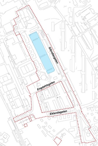
The energy demand assessment refers to the existing context, therefore it describes how the proposed design alternative for the new buildings will impact the existing buildings. As the open area given for the study is large (Figure ), one unit is considered for each street in front of the proposed site, i.e. 20 units. The simulations are performed using the Rhino/Grasshopper plug-in HoneybeeFootnote2 which uses Energy Plus as the calculation engine. The existing buildings are assumed to be offices. The thermal properties of the envelope and the user profiles are taken from ASHRAE (Halverson et al. Citation2014), such as U-values, the internal gain per equipment and people, occupancy schedules, temperature setpoints, etc. Leveraging the full potential of digital twinning, we utilize the pressure coefficient results from the wind simulations, shown in Figure A2, as input for the energy simulations. We follow the approach suggested in Charisi, Waszczuk, and Thiis (Citation2021) where an improvement of the evaluation of the buildings’ air infiltration could be obtained when using CFD simulation results instead of standard tabulated values for the pressure coefficient. This approach exemplifies the potential of having different simulation capabilities communicating with each other. It is worth noting that more complex coupling procedures have been suggested for building energy and CFD simulations, e.g. in (Rabani, Madessa, and Nord Citation2021) which require a closer communication of the solvers. These coupling procedures might go beyond the possibilities of a digital twin as the communication platform.
Figure 2. The area Gibraltarvallen where the blue rectangle marks the site where the different alternatives will be installed.
The area to be analysed for the solar radiation concentrates on the public space within the study area. A flat grid with a grid size of 8 metre is used. The simulations are carried out using Honeybee and Radiance. For each design alternative, the resulting solar radiation is compared to a base case without new buildings to show how much radiation is lost due to the new buildings in each alternative.
2.2.3. Noise levels
The noise levels due to road traffic in the area are calculated according to local regulations, following the Nordic Prediction Method for Road Traffic Noise (Nordic Council of Ministers Citation1996). The model uses data on the elevation of the terrain, ground type (acoustically soft or hard), buildings and noise barriers (footprint and height) and location of road segments with accompanying data on traffic flow (driving speed and number of light and heavy vehicles per 24 h). The model can be used to predict both 24 h-equivalent noise level and maximum noise level due to passage of the noisiest vehicle type. Here, equivalent levels were calculated and presented as day-evening-night noise level (Lden in dB). The indicator Lden applies a penalty on evening and night levels and is used within the EU. In the presented study, also the daytime level (Lday) is of interest, which here is estimated to be 1.6 dB lower than Lden. The model is implemented in numeric code (using Matlab and Python) to calculate the noise level at a grid of receiver positions elevated 2 metre above the ground surface, i.e. a grid noise map. Also, facade noise level calculations can be made. The ground surface model (sampled at 2-metre grid size) and built elements are provided from the developed workflow as described above whereas the road segments are imported as shapefiles with the traffic data as attributes. In the calculation, each road segment is divided into a set of acoustic point sources and for each source–receiver pair the noise level contribution is calculated following the Nordic Prediction Method (including one facade reflection), where a vertical cut plane defines the propagation condition in terms of ground profile, ground type and shielding objects. As post-processing, the total noise level at each receiver position (grid point) is collected and exported as CSV files for further analysis.
2.3. Case study
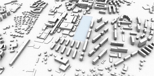
As a case area, we chose a site currently used as a parking space, but of local interest because of its central location and possibilities for densification. The area is centrally located in Gothenburg, Sweden. The densification plan covers a total of 11 hectares; however, this study only considers the current unused area (Figures and Figure ).
Figure 3. Site where the different alternatives will be installed.
The region has a west coast marine climate characterized by recurrent low- and high-pressure systems embedded in westerly flows. Long periods of stable weather are more infrequent due to blocking anticyclone over Scandinavia. With an average air temperature of −1.3°C in winter (December-February) and 14.5°C in summer (June–August), the area experiences comparatively mild winters and cool summers for its latitude (Thorsson et al. Citation2011).
Seven design alternatives were randomly generated as described in Step 2 of the workflow. As can be seen in Figure , alternatives 1, 2, and 3 use disconnected blocks along the intervention area. These blocks have different heights but are distributed in parallel at a fixed distance, creating corridors and in some cases canyons. Alternatives 6 and 7 have a connected block design, the characteristic of which is that they create semi-enclosed courtyards, while alternatives 4 and 5 have mixed formats. The current situation with the parking lot without buildings is defined as base case.
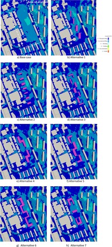
Figure 4. Base case without buildings and design alternatives with new buildings tested in the case study.
3. Results
The following section provides information about the simulation results of the different performance indicators for the different design alternatives. First, we present the separate results in section 3.1 before giving an overview of the combined results in 3.2.
3.1. Individual simulation results
While the present work anticipates bringing forward a streamlined workflow for multi-domain simulations using digital twins and not a concrete design proposal for the studied case, we discuss the individual results to show the level of detail that can be obtained. In the following, we discuss the base case without a design proposal first and then discuss the performance of the different design alternatives.
3.1.1. Wind comfort
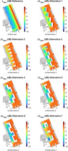
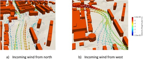
The Lawson LDCC wind comfort criterion is evaluated in a larger area around the site. However, the results are focused on the target area, which can be seen in Figure (a). In this Figure, the site without the proposed buildings yields a wind comfort of class B in most of the area. Class B of this wind comfort criterion is considered comfortable for occasional sitting which can be considered reasonable for utilization of outdoor activities like accompanying children at the playground, e.g. sitting on benches reading, etc. However, there is a significant area with only a medium wind comfort class C, which is more suitable for standing. When looking at the single direction simulation results shown in the Appendix, it becomes visible that wind coming from the north, shown in the Appendix A1 in Figure A1(a), (but also from the south, not shown) blows straight through the target area and results in high wind speeds. Yet, when the wind blows from the west, shown in Figure A1(b), it is directed downwards when reaching the area and is redirected again when reaching the buildings on the western side, resulting in high wind speeds towards south. For a prospering use of the entire area, the building proposals should be designed to keep the area with the class C wind comfort as small as possible. This means it becomes important to shelter the area from wind just blowing through and from down fall effects.
Figure 5. Wind comfort.
Looking at the following images in Figure containing the different design alternatives, it is visible that all alternatives can decrease the area with lower wind comfort to some degree. However, it is also visible that the influence of the included buildings is very limited regarding the surrounding buildings, streets, and places. There is almost no change in the wind comfort visible outside of the site except for the row of buildings directly to the south. Hence, we discuss only on the site itself.
The buildings in alternatives 1, 2, and 4 have a limited impact. They are hardly able to increase the wind comfort further away from the buildings and can only generate some small, shielded areas close to the buildings. Alternatives 3, 5, and 6 with their staggered structure can shield the space between the buildings significantly and reduce the downfall of the wind and reduce the blow through the area. They furthermore increase the wind comfort eastwards and further away from the buildings.
Alternative 7 has a particular shape that leads to increased wind comfort in the northern part of the buildings and reduces the area with class C wind comfort. However, the overall effect seems to be less pronounced in the lower part.
In summary, alternatives 3, 5, and 6 are performing significantly better than the other alternatives. A quantitative analysis of the reduction of the area with wind classes C and B, shows that Alternatives 3 and 6 reduce the area with class C. Combing the areas of classes C and B shows that alternative 6 is slightly more advantageous.
3.1.2. Energy and solar radiation
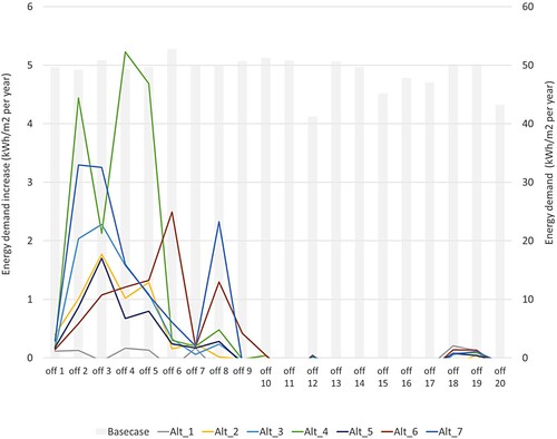
The energy demand for heating and cooling of the existing buildings in the base case shows different needs, ranging from 50 to 213 kWh/m2 per year (Figure ). The differences are mainly due to the dimensions and geometry of each building. Some are compact and with less exposed areas, while others have complex geometries and are isolated. When assessing the increase in energy demand due to the different alternatives for a new building, some alternatives have a greater impact on certain buildings, mainly those facing east (office buildings 1–13). There is a maximum increase of 4.5 kWh/m2 per year (office building 1) caused by design alternative 1 (Figure ). Considering the total energy demand per design alternative, Alternatives 1 and 7 show the highest negative impact, adding up to an increase of 22.3 and 28.2 kWh/m2 per year in the neighbourhood. The alternatives with the least energy increase are alternatives 5 and 6 with 10.2 and 14.4 kWh/m2 per year respectively.
Figure 6. Yearly energy demand of the existing buildings in the base case.
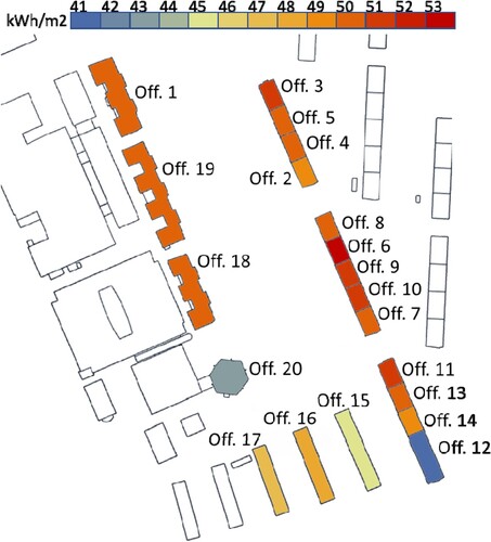
Figure 7. Change in energy demand of existing office buildings for each design alternative.
In general, all design alternatives increase the energy demand, indicating that it becomes difficult to design new buildings that do not negatively affect the energy performance of neighbouring buildings. This is due to the variations in solar radiation resulting from the placement of each alternative, as the amount and distribution of solar radiation reaching neighbouring buildings changes for each alternative. For instance, one alternative may cast more shadow on nearby buildings, while another may reflect more sunlight onto them. This is explained in more detail in the solar radiation analysis. To translate the energy load in the study into concrete terms, the alternative with the highest negative impact would mean the addition of a new 200 m2 building consuming almost 50 kWh/m2 per year.
The results of the solar radiation simulation for the base case are presented in Figure (a), where it is also possible to see the target area to be analysed. Figure (b–h) shows the radiation losses with respect to the base case due to the new buildings. All alternatives show the highest losses in the immediate surroundings of the new buildings, with the losses being more intense towards the north. This is linked to the path of the sun. It should be noted that the heights of the buildings also condition these energy losses, for example alternatives 1 and 7 have the highest buildings, reaching seven storeys. Alternatives 5 and 6 have a maximum of three storeys and most of the buildings have only one level. Considering the orientation and height of the buildings in the different proposals, it is easy to understand how the solar radiation losses are distributed and how each proposal places the extra energy demands on the existing buildings.
Figure 8. Solar radiation of the base case and delta between the solar radiation of the base case with each alternative.
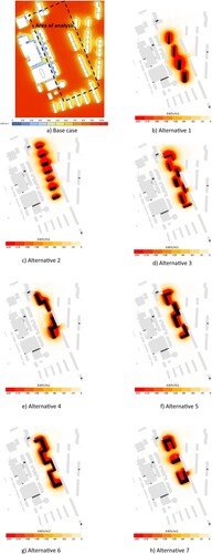
By reviewing alternative 7 in Figure , we can see that the solar radiation losses affect the buildings adjacent to the proposal, especially those facing east, because the solar radiation is more intense from noon to sunset than from morning to noon. This means that buildings to the east receive less solar radiation than when there were no buildings blocking the sun. The same situation can be seen in alternatives 1, 2, and 3, while alternatives 5 and 6 show a much more limited area of impact, distant from the buildings surrounding the proposal. Therefore, these alternatives have the least impact on the increase of energy demand in the neighbourhood.
3.1.3. Noise levels
The calculated grid noise map data (Figure ) shows the noise level in the situation without new buildings (base case) together with the differences in noise level when alternatives 1–7 are introduced. It can be seen in the base case that the noise level is fairly high close to the main road (Lden about 65 dB at 10-metre distance from road). The introduction of new buildings can be seen to both cause a slight increase in noise level towards the roads (up to 2 dB increase) and a large reduction in noise level at locations where the new buildings are shielding the line-of-sight from the main road (up to 9 dB decrease). Using a daytime level (Lday) of 50 dB or less as an indicator for an acceptable outdoor noise level, e.g. (Nilsson and Berglund Citation2006) one finds that all of the design alternatives provide a better solution than the base case, which only has 7% of the site fulfilling Lday ≤ 50 dB. Among the design alternatives, alternatives 1 and 3 provide the best result, with 35% of the outdoor calculation area fulfilling Lday ≤ 50 dB, followed by alternatives 4, 5, and 6 with results in the range 31–32%. The worst are alternatives 2 and 7, reaching 24% and 26% respectively. It can be concluded that increasing the length of the facade towards the main road is advantageous in combination with locating the buildings as close as possible to the main road for maximizing the size of area below a given noise limit.
Figure 9. Grid noise maps for (a) base case without new buildings, and (b–h) different maps for design alternatives 1–7.
3.2. Integrated result analysis
Analysing and visualizing complex phenomena in a 3D model can help to understand them, but integrating results from domains such as wind, solar radiation, energy, and noise can be difficult. Two major challenges are the normalization of results from each domain for a holistic comparison to determine the best design alternative; and the simultaneous representation of results in the 3D model for consistent interpretation, verification, and analysis.
To address these challenges, a multi-domain workflow was employed. Results were manually normalized according to their respective domains and each alternative was ranked according to its performance. The 3D model was utilized for a combined visualization allowing a comprehensive visual result analysis.
3.2.1. Impact of each domain studied with respect to the base case
To make it easier to interpret the individual results and rank them, the key performance indicators are normalized using the performance of the base case. This normalization process could fit any project, as it is not tailored to this study, but different ways of normalization could be applied.
For wind, the comfort-level weighted area has been used to derive a single quantity. When normalized with the base case, it can be interpreted as the share of the area with improved wind comfort. In the case of noise, the area with Lden less than or equal to 50 dB compared to the base case was used for normalization. For the energy demand, the total energy demand of all existing buildings was calculated for the base case and then the same simulation was performed including each design alternative as an obstruction. The difference between each design alternative and the base case was then calculated. The normalization used assumes that the energy demand of the existing buildings is 50% better or worse than the base case.
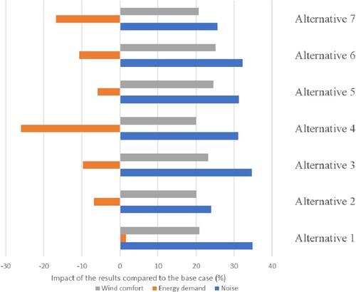
When reviewing the results of the three performance indicators in Figure , it becomes clear that all design alternatives provide positive change with regard to noise and wind comfort. In the case of noise, the improvements compared to the base case are between 35–24%, while a 25–20% improvement in wind comfort can be achieved. This is because the new buildings, independent of shape and orientation, are shown to be effective in attenuating noise propagation and reducing wind speed. In contrast, the energy demand of existing buildings increases regardless of the design alternative.
Figure 10. Change of performance indicators of each design alternative compared to the base case of the case study (positive values indicate increase in performance).
3.2.2. Combining results and ranking of design alternatives
Decision-making on three (or more) different indicators can be difficult in practice. Therefore, the three indicators are exemplary combined into a single indicator by summing up the percentage values. This corresponds to giving equal weight to each of the domains wind comfort, noise, and energy. Different weighting approaches could be introduced in other studies. The resulting overall performance of each design alternative is shown in Table .
Table 1. Combined results for each design alternative.
It can be seen from the results after ranking that the performance indicator with the greatest spread in results between the different alternatives is energy demand. This means that the variations associated with each design alternative here have a greater impact on energy demand than on the performance regarding noise or wind comfort.
The design alternatives are assessed based on overall performance, with alternatives 4 and 7 emerging as the least favourable choices. In terms of energy efficiency, this can be attributed to the impact of infiltration, closely linked to wind pressure. Alternatives 4 and 7 feature lower buildings, with a single tall structure that impedes wind speed reduction. The presence of this tall building, positioned in close proximity to existing structures, diminishes the amount of solar radiation received by these adjacent buildings.
In the context of noise, alternative 7 exhibits poor performance, primarily due to a relatively short length of shielding façade facing the main road. Additionally, the buildings in this alternative are situated at a notable distance from the main road. The top-ranking alternatives are options 1 and 5. These alternatives feature a mixed distribution of building heights, ranging from 1 to 5 stories. This arrangement has a positive impact on energy efficiency. Placing taller buildings in the centre of the layout prevents a reduction in solar radiation that neighbouring buildings can capture, while also mitigating wind pressure.
In terms of estimated noise levels, alternatives 1 and 5 yield intermediate results. This outcome is attributed to the advantageous extended facade facing the main road, combined with the buildings being situated at a reasonable distance from the main road.
3.2.3. Visualization of the results
As an example of how the combined simulation results could be presented to stakeholders, an interactive WebGL visualization was created using the JavaScript framework three.jsFootnote3 as shown in Figure . Radiation and noise results are visualized using point particles coloured according to their respective values. Wind results are rendered as a triangulated mesh, coloured corresponding to the Lawson LDDC categories of the cells. The building colour visualizes its energy demand. HTML-based legends show how the colours map to the simulation result values.
Figure 11. Example representation of the combined visualization of wind comfort, building energy consumption and noise for design alternative 1. The top image shows energy, noise, and wind visualized together, whereas the bottom image visualizes energy and solar radiation.
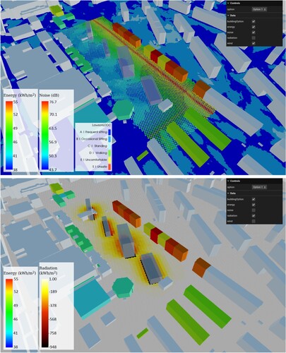
The user interfaceFootnote4 includes a toolbar to select different design alternatives, switching between the distinct datasets. The interface also has the option to toggle different data on or off; for example, hiding the wind data to not occlude the radiation data. An interactive investigation of the results by the stakeholders allows a comprehensive communication and such an opportunity can be given within the digital twin.
4. Discussion
As mentioned earlier, a complete Digital Twin should enable a seamless real-time connection between the digital twin and the physical world, allowing for the control of physical entities without human intervention (Friedrich-Alexander Citation2019). Constructing a digital twin city necessitates both a data foundation and a technical foundation. Similarly, smart cities share commonalities with the ideal Digital Twin Cities as both are constructed on data across different levels and domains to interact effectively with the physical model. To clarify, smart cities are urban areas that employ Information and Communication Technology (ICT) to sense, analyse, and integrate critical information from their core systems (IBM Industry Solutions Citation2019). Consequently, smart cities can intelligently respond to various needs related to livelihood, environmental preservation, safety management, and economic activities (Su, Li, and Fu Citation2011). Thus, a Digital Twin can be created using the data established in a smart city. However, the challenge lies in the fact that smart cities are not uniformly implemented, and those that claim to be ‘smart cities’ often use different definitions of the term. Becoming a smart city requires the establishment of a substantial data infrastructure, which demands significant resources and time for proper implementation. This also has an impact on the development of a Digital Twin city. The workflow proposed in this paper has the potential to significantly contribute to the implementation of digital twins. It establishes the technical infrastructure for processing and analysing data based on simulations. This infrastructure is flexible and can be easily extended to cover additional domains. Furthermore, it serves as a platform for future integration of real-world data, thereby fostering the development of digital twin cities and smart cities.
4.1. Applicability of the approach in urban planning
The advantages of using a streamlined and integrated multi-domain workflow lie in the possibility to analyse a variety of different environmental key performance indicators for multiple design alternatives based on a single source of input. The workflow allows combining the results, evaluating the overall performance, and finding the best design alternative. As seen in the presented case study, it is possible that different design alternatives perform best in the different domains. Hence, a combined qualitative and quantitative analysis also weighting the importance of the different environmental variables should be performed based on all available simulation results to evaluate the overall performance.
The detailed cross-evaluation of the results made it possible to assess different hypothetical design alternatives and to determine to what extent they affect the existing neighbourhood. With this combined interdisciplinary analysis identifying the reasons for an alternative to perform better or worse and possible environmental disturbances, an understanding and knowledge raise is achieved. Moreover, as the developed workflow ensures a single source of the 3D geometry, both of the existing terrain and buildings as well as the design alternatives. This helps to ensure the quality and accuracy of the input data for all performed simulations, even across different tools. This facilitates a streamlined simulation and analysis process without the need for manual intervention. Further, bringing together the input data and the simulation results on a single platform allows to visualize the results in an integrated manner. Bringing together the domain experts to generate a comprehensive combined visualization facilitates the communication of the combined simulation results between the domain experts, who are usually not experts in the adjacent domains, and to other stakeholders and non-experts in general. This in turn allows the creation of consensus on critical areas for further analysis or for discussion when proposing improvements, design guidelines and restrictions on urbanization plans. A quantitative analysis furthermore facilitates decision making and synthesizes the assessment of the different design alternatives within a single graph.
4.2. Limitations and future work
The proposed workflow should be seen as a step forward in developing a streamlined and harmonized workflow for urban multi-domain performance simulations using digital twins of cities. Currently, not all steps in the workflow are entirely automated. We have not yet approached a perfect interoperability and a formulation of standardized input and output formats and data models. However, as this aspect is key to a functioning and vivid digital twin city, adopting and bringing open standards forward is intended in ongoing work. In the future, the DTCC Builder [34] will be developed further to allow for further automatization. Furthermore, the DTCC ViewerFootnote5 as a web solution is still under development and will allow for more visualization features in the future.
Here, the combination of the individual results into one result was based on a scale developed by experts’ judgement and a simple equal weighting of the three domains was applied. In a real case study, the importance of the individual domains might vary very much to different stakeholders. Therefore, a weighting scheme should be developed together with the stakeholders before the combination of results.
For the simulations, a single Typical Meteorological Year (TMY) weather file was utilized across all tools. Although it is possible to re-input the climate data with the results of the simulations, the decision was made not to carry out this procedure at this stage of the study. However, there is a consideration to perform such a procedure in the future, provided that it is confirmed to be worthwhile to include such a calculation. On initial assessment, it should not result in significant alterations, as, for instance, in the case of wind, wind pressures are already considered on a localized basis. Additionally, radiation is accounted for as obstructions. The temperature change due to heat islands could potentially introduce notable variations in summer, but it is worth noting that the highest energy consumption is associated with the winter period.
The greenery influences all the performance indicators studied, reduces solar radiation on facades, decreases wind speeds, and helps to reduce noise propagation. However, this was not considered in the study, as the interest of our project was to show the impact of the new buildings on the environment. Clearly the results would have been different if we had considered the greenery. The greenery could be integrated into the workflow in the future. Automatized ways to generate greenery have been developed before using the same input data as starting point (Thuvander, Somanath, and Hollberg Citation2022).
Another limitation of the study is the disparity in the analysis periods, i.e. not all simulations covered the whole year. For example, the solar radiation considered the summer and winter seasons, since these are the determining periods in the variations in energy demand, while the wind simulations were performed using the wind rose of the entire year not distinguishing seasonal differences. Hence, an even more detailed analysis of the considered urban environmental variable is possible to perform.
Finally incorporating environmental performance analyses of other domains, such as rainstorm, sky view factor, illumination, etc. is considered for further extension of the presented work. Moreover, the usage of an outdoor thermal comfort indicator that combines some of the analysed quantities (i.e. radiation, wind, heat) in its calculation is ongoing work. This approach will allow the positive and negative impacts of each scenario to be assessed under a single indicator.
5. Conclusion
The aim of this article was to bring forward a streamlined and harmonized workflow based on an urban digital twin to allow for environmental performance optimization of urban design using multi-domain simulations. The results of the case study show that digital twins of cities can provide a common basis for multi-domain simulations. The digital twin was also used to facilitate data exchange between the simulation tools enhancing the quality of simulation results. The basic 3D model of the city can be adapted to match the needs of the different input formats and requirements for the different simulation engines. Furthermore, bringing together the simulation results in a combined visualization provides a more harmonized mode of presentation which enables a clear communication of the findings to both experts and non-experts. The workflow reduces the manual work currently needed when applying different simulation software for different domains of urban planning. This is especially important when design optimization by comparison of multiple variants shall be carried out. The case study showed that the automatized workflow makes it feasible in practice to efficiently carry out multi-domain analysis. This is one step forward in streamlining the workflow for urban analysis, which contributes to the uptake of multi-domain simulations in urban planning in practice.
Acknowledgements
The authors would like to acknowledge support from InfraVis for providing application expertise for visualization through Swedish Research Council grant 2021-00181. Further, the authors would like to acknowledge the comments and fruitful discussion with Alejandro Pacheco Diéguez from White Arkitekter.
Disclosure statement
No potential conflict of interest was reported by the author(s).
Data availability statement
The participants of this study did not give written consent for their data to be shared publicly, so due to the sensitive nature of the research supporting data is not available. Data can be made accessible by individual request to the authors.
Additional information
Funding
Notes
1 Research Competence Centre funded by the Swedish Agency for Innovation Systems (Vinnova) and lead by Chalmers University, https://dtcc.chalmers.se/.
References
- Agugiaro, Giorgio, Joachim Benner, Piergiorgio Cipriano, and Romain Nouvel. 2018. “The Energy Application Domain Extension for CityGML Enhancing Interoperability for Urban Energy Simulations.” Open Geospatial Data, Software and Standards 3 (1): 2. https://doi.org/10.1186/s40965-018-0042-y.
- Ahmadian, Ehsan, Behzad Sodagar, Chris Bingham, Amira Elnokaly, and Glen Mills. 2021. “Effect of Urban Built Form and Density on Building Energy Performance in Temperate Climates.” Energy and Buildings 236:110762. https://doi.org/10.1016/j.enbuild.2021.110762.
- Alves, Sonia, Laura Estévez-Mauriz, Francesco Aletta, Gemma M. Echevarria-Sanchez, and Virginia Puyana Romero. 2015. “Towards the Integration of Urban Sound Planning in Urban Development Processes: The Study of Four Test Sites Within the SONORUS Project.” Noise Mapping 2 (1). https://doi.org/10.1515/noise-2015-0005.
- Aupoix, B. 2014. “Roughness Corrections for the k–ω Shear Stress Transport Model: Status and Proposals.” Journal of Fluids Engineering 137 (2): 021202. https://doi.org/10.1115/1.4028122.
- Biljecki, Filip, Hugo Ledoux, and Jantien Stoter. 2016. “An Improved LOD Specification for 3D Building Models.” Computers, Environment and Urban Systems 59:25–37. https://doi.org/10.1016/j.compenvurbsys.2016.04.005.
- Brozovsky, J., J. Radivojevic, and A. Simonsen. 2022. “Assessing the Impact of Urban Microclimate on Building Energy Demand by Coupling CFD and Building Performance Simulation.” Journal of Building Engineering 55:104681. https://doi.org/10.1016/j.jobe.2022.104681.
- Brozovsky, Johannes, Are Simonsen, and Niki Gaitani. 2021. “Validation of a CFD Model for the Evaluation of Urban Microclimate at High Latitudes: A Case Study in Trondheim, Norway.” Building and Environment 205:108175. https://doi.org/10.1016/j.buildenv.2021.108175.
- Caprari, Giorgio. 2022. “Digital Twin for Urban Planning in the Green Deal Era: A State of the Art and Future Perspectives.” Sustainability 14 (10): 6263. https://doi.org/10.3390/su14106263.
- Charisi, Stergiani, Milosz Waszczuk, and Thomas K. Thiis. 2021. “Determining Building-Specific Wind Pressure Coefficients to Account for the Microclimate in the Calculation of Air Infiltration in Buildings.” Advances in Building Energy Research 15 (3): 368–389. https://doi.org/10.1080/17512549.2019.1596835.
- City of London Corporation. 2019. Wind Microclimate Guidelines for Developments in the City of London, 1–15.
- de Wilde, Pieter. 2023. “Building Performance Simulation in the Brave New World of Artificial Intelligence and Digital Twins: A Systematic Review.” Energy and Buildings 292:113171. https://doi.org/10.1016/j.enbuild.2023.113171.
- Dorer, V., J. Allegrini, K. Orehounig, P. Moonen, G. Upadhyay, J. Kampf, and J. Carmeliet. 2013. “Modelling the Urban Microclimate and Its Impact on the Energy Demand of Buildings and Building Clusters.” Paper Presented at the 13th International Conference of the International-Building-Performance-Simulation-Association (IBPSA), August 25–28, Chambery, France.
- DTCC Builder. 2022. “Data Processing, Modeling and Simulation for the Digital Twin Cities Platform.” https://gitlab.com/dtcc-platform/dtcc-builder.
- Du, Yaxing, Cheuk Ming Mak, and Bo-Sin Tang. 2018. “Effects of Building Height and Porosity on Pedestrian Level Wind Comfort in a High-Density Urban Built Environment.” Building Simulation 11 (6): 1215–1228. https://doi.org/10.1007/s12273-018-0451-y.
- EEA (European Environment Agency). 2020. Environmental Noise in Europe, 2020. EEA Report No 22/2019: Publications Office.
- Eliasson, Ingegärd, Igor Knez, Ulla Westerberg, Sofia Thorsson, and Fredrik Lindberg. 2007. “Climate and Behaviour in a Nordic City.” Landscape and Urban Planning 82 (1–2): 72–84. https://doi.org/10.1016/j.landurbplan.2007.01.020.
- Enders, Martin Robert, and Nadja Hoßbach. 2019. “Dimensions of Digital Twin Applications – a Literature Review.”AMCIS 2019 Proceedings. 20. https://aisel.aisnet.org/amcis2019/org_transformation_is/org_transformation_is/20
- Forssén, Jens, Andreas Gustafson, Meta Berghauser Pont, Marie Haeger-Eugensson, Christine Achberger, and Niklas Rosholm. 2022. “Effects of Urban Morphology on Traffic Noise: A Parameter Study Including Indirect Noise Exposure and Estimated Health Impact.” Applied Acoustics 186:108436. https://doi.org/10.1016/j.apacoust.2021.108436.
- Girin, Arnaud. 2021. “Lawson Wind Comfort Criteria: A Closer Look. Simscale Blog.” Accessed October 25, 2022. https://www.simscale.com/blog/lawson-wind-comfort-criteria/.
- Grieves, Michael. 2014. “Digital Twin: Manufacturing Excellence Through Virtual Factory Replication.” White Paper 1:1–7.
- Halverson, Mark A., Michael I. Rosenberg, Philip R. Hart, Eric E. Richman, Rahul A. Athalye, and David W. Winiarski. 2014. ANSI/ASHRAE/IES Standard 90.1-2013 Determination of Energy Savings: Qualitative Analysis. Richland, WA: Pacific Northwest National Lab. (PNNL).
- IBM Industry Solutions. 2019. “IBM Smarter Cities-Creating Opportunities Through Leadership and Innovation.” IBM. Accessed May 19. https://goo.gl/7aLzQM.
- Javanroodi, Kavan, and Vahid M. Nik. 2019. “Impacts of Microclimate Conditions on the Energy Performance of Buildings in Urban Areas.” Buildings 9 (8): 189. https://doi.org/10.3390/buildings9080189.
- Kaijima, Sawako, Roland Bouffanais, Karen Willcox, and Suresh Naidu. 2013. “Computational Fluid Dynamics for Architectural Design.” Architectural Design 83 (2): 118–123. https://doi.org/10.1002/ad.1566.
- Ketzler, Bernd, Vasilis Naserentin, Fabio Latino, Christopher Zangelidis, Liane Thuvander, and Anders Logg. 2020. “Digital Twins for Cities: A State of the Art Review.” Built Environment 46 (4): 547–573. https://doi.org/10.2148/benv.46.4.547.
- Klingberg, Jenny, Malin Broberg, Bo Strandberg, Pontus Thorsson, and Håkan Pleijel. 2017. “Influence of Urban Vegetation on Air Pollution and Noise Exposure – a Case Study in Gothenburg, Sweden.” Science of The Total Environment 599–600:1728–1739. https://doi.org/10.1016/j.scitotenv.2017.05.051.
- Kritzinger, Werner, Matthias Karner, Georg Traar, Jan Henjes, and Wilfried Sihn. 2018. “Digital Twin in Manufacturing: A Categorical Literature Review and Classification.” IFAC-PapersOnLine 51 (11): 1016–1022. https://doi.org/10.1016/j.ifacol.2018.08.474.
- Lee, Pyoung Jik, and Jian Kang. 2015. “Effect of Height-to-Width Ratio on the Sound Propagation in Urban Streets.” Acta Acustica United With Acustica 101:73–87. https://doi.org/10.3813/AAA.918806.
- Lehtola, Ville V., Mila Koeva, Sander Oude Elberink, Paulo Raposo, Juho-Pekka Virtanen, Faridaddin Vahdatikhaki, and Simone Borsci. 2022. “Digital Twin of a City: Review of Technology Serving City Needs.” International Journal of Applied Earth Observation and Geoinformation 114:102915. https://doi.org/10.1016/j.jag.2022.102915.
- Logg, A., and V. Naserentin. 2022. “Modelling and Simulating Cities with Digital Twins.” GIM International.
- Loibl, Wolfgang, Milena Vuckovic, Ghazal Etminan, Matthias Ratheiser, Simon Tschannett, and Doris Österreicher. 2021. “Effects of Densification on Urban Microclimate – a Case Study for the City of Vienna.” Atmosphere 12 (4): 511. https://doi.org/10.3390/atmos12040511.
- Lyden, Andrew, Russell Pepper, and Paul G. Tuohy. 2018. “A Modelling Tool Selection Process for Planning of Community Scale Energy Systems Including Storage and Demand Side Management.” Sustainable Cities and Society 39:674–688. https://doi.org/10.1016/j.scs.2018.02.003.
- Mark, Andreas, Robert Rundqvist, and Fredrik Edelvik. 2010. “Comparison Between Different Immersed Boundary Conditions for Simulation of Complex Fluid Flows.” Fluid Dynamics & Materials Processing 7 (3): 241–258.
- Mauree, Dasaraden, Emanuele Naboni, Silvia Coccolo, A. T. D. Perera, Vahid M. Nik, and Jean-Louis Scartezzini. 2019. “A Review of Assessment Methods for the Urban Environment and Its Energy Sustainability to Guarantee Climate Adaptation of Future Cities.” Renewable and Sustainable Energy Reviews 112:733–746. https://doi.org/10.1016/j.rser.2019.06.005.
- Merlier, Lucie, Frédéric Kuznik, Gilles Rusaouën, and Serge Salat. 2018. “Derivation of Generic Typologies for Microscale Urban Airflow Studies.” Sustainable Cities and Society 36:71–80. https://doi.org/10.1016/j.scs.2017.09.017.
- Mirashk-Daghiyan, Maryam, Atefeh Dehghan-Touran-Poshti, Azadeh Shahcheragi, and Mohammad Hadi Kaboli. 2022. “The Effect of Surrounding Buildings’ Height and the Width of the Street on a Building’s Energy Consumption.” International Journal of Energy and Environmental Engineering 13 (1): 207–217. https://doi.org/10.1007/s40095-021-00420-1.
- Mittal, Hemant, Ashutosh Sharma, and Ajay Gairola. 2018. “A Review on the Study of Urban Wind at the Pedestrian Level Around Buildings.” Journal of Building Engineering 18:154–163. https://doi.org/10.1016/j.jobe.2018.03.006.
- Montazeri, H., and B. Blocken. 2013. “CFD Simulation of Wind-Induced Pressure Coefficients on Buildings with and Without Balconies: Validation and Sensitivity Analysis.” Building and Environment 60:137–149. https://doi.org/10.1016/j.buildenv.2012.11.012.
- Naserentin, Vasilis, and Anders Logg. 2022. “Digital Twins for City Simulation: Automatic, Efficient, and Robust Mesh Generation for Large-Scale City Modeling and Simulation.” arXiv preprint arXiv:2210.05250.
- Nilsson, Mats E., and Birgitta Berglund. 2006. “Soundscape Quality in Suburban Green Areas and City Parks.” Acta Acustica United With Acustica 92:903–911.
- Nordic Council of Ministers. 1996. Road Traffic Noise: Nordic Prediction Method. Vol. 525. TemaNord: The Stationery Office Books.
- Nouvel, R., K.-H. Brassel, M. Bruse, E. Duminil, V. Coors, U. Eicker, and D. Robinson. 2015. “SimStadt, a New Workflow-Driven Urban Energy Simulation Platform for CityGML City Models.” In CISBAT International Conference. Lausanne.
- Pont, Meta Berghauser, Jens Forssén, Marie Haeger-Eugensson, and Andreas Gustafsson. 2019. “Increasing Cities’ Capacity to Manage Noise and Air Quality Using Urban Morphology.”
- Rabani, Mehrdad, Habtamu Bayera Madessa, and Natasa Nord. 2021. “Building Retrofitting Through Coupling of Building Energy Simulation-Optimization Tool with CFD and Daylight Programs.” Energies 14 (8): 2180. https://doi.org/10.3390/en14082180.
- Saeed, Zaid O., Francesco Mancini, Tanja Glusac, and Parisa Izadpanahi. 2022. “Future City, Digital Twinning and the Urban Realm: A Systematic Literature Review.” Buildings 12 (5): 685. https://doi.org/10.3390/buildings12050685.
- Shahat, Ehab, Chang T. Hyun, and Chunho Yeom. 2021. “City Digital Twin Potentials: A Review and Research Agenda.” Sustainability 13 (6): 3386. https://doi.org/10.3390/su13063386.
- Sola, Alaia, Cristina Corchero, Jaume Salom, and Manel Sanmarti. 2018. “Simulation Tools to Build Urban-Scale Energy Models: A Review.” Energies 11 (12): 3269. https://doi.org/10.3390/en11123269.
- Su, K., J. Li, and H. Fu. 2011. “Smart City and the Applications.” Paper Presented at the 2011 International Conference on Electronics, Communications and Control (ICECC), 9–11 September 2011, Ningbo.
- Thorsson, Sofia, Fredrik Lindberg, Jesper Björklund, Björn Holmer, and David Rayner. 2011. “Potential Changes in Outdoor Thermal Comfort Conditions in Gothenburg, Sweden due to Climate Change: The Influence of Urban Geometry.” International Journal of Climatology 31 (2): 324–335. https://doi.org/10.1002/joc.2231.
- Thuvander, L., S. Somanath, and A. Hollberg. 2022. “Procedural Digital Twin Generation for Co-Creating in VR Focusing on Vegetation.” The International Archives of the Photogrammetry, Remote Sensing and Spatial Information Sciences 48:189–196. https://doi.org/10.5194/isprs-archives-XLVIII-4-W5-2022-189-2022.
- Tollin, Nicola, J. Hamaber, S. Grafakos, S. Lwasa, and J. Morato. 2017. Sustainable Urbanization in the Paris Agreement – a Comparative Review of Nationally Determined Contributions for Urban Content. Nairobi: UN-Habitat.
- Tzachor, Asaf, Soheil Sabri, Catherine E. Richards, Abbas Rajabifard, and Michele Acuto. 2022. “Potential and Limitations of Digital Twins to Achieve the Sustainable Development Goals.” Nature Sustainability 5 (10): 822–829. https://doi.org/10.1038/s41893-022-00923-7.
- United Nations. 2019. World Urbanization Prospects: The 2018 Revision (ST/ESA/SER.A/420). New York: United Nations.
- United Nations Climate Change. 2016. “The Paris Agreements, 4th November 2016.”
- United Nations, Department of Economic and Social Affairs, Population Division. 2018. The World’s Cities in 2018 – Data Booklet (ST/ESA/ SER.A/417).
- Vanky, Patricia, Andreas Mark, Marie Haeger-Eugensson, Joaquim Tarraso, Marco Adelfio, Angela Sasic, and Gaetano Sardina. 2022. “Validation of Animmersed Boundary Framework for Urban Flows.” In Conference on Modelling Fluid Flow (CMFF’22), Budapest, Hungary.
- Venter, Zander S., Norun Hjertager Krog, and David N. Barton. 2020. “Linking Green Infrastructure to Urban Heat and Human Health Risk Mitigation in Oslo, Norway.” Science of The Total Environment 709:136193. https://doi.org/10.1016/j.scitotenv.2019.136193.
- Wang, Pengcheng, Zhongbing Liu, and Ling Zhang. 2021. “Sustainability of Compact Cities: A Review of Inter-Building Effect on Building Energy and Solar Energy Use.” Sustainable Cities and Society 72:103035. https://doi.org/10.1016/j.scs.2021.103035.
- Wieringa, Jon. 1992. “Updating the Davenport Roughness Classification.” Journal of Wind Engineering and Industrial Aerodynamics 41 (1–3): 357–368. https://doi.org/10.1016/0167-6105(92)90434-C.
- Yin, Chaohui, Man Yuan, Youpeng Lu, Yaping Huang, and Yanfang Liu. 2018. “Effects of Urban Form on the Urban Heat Island Effect Based on Spatial Regression Model.” Science of the Total Environment 634:696–704. https://doi.org/10.1016/j.scitotenv.2018.03.350.
Appendix
A1. Wind simulation result analysis
Figure A1. Streamlines across the target area, which can be seen in Figure (a).
A2. Wind pressure coefficients (Cp)
Figure A2. Wind pressures coefficient used for infiltration calculation in energy demand simulation, exemplary shown for northern wind for all design alternatives.
