Abstract
Pumping of wells from aquifers that are used to supply brackish-water reverse osmosis (BWRO) treatment systems commonly causes increases of water salinity in time. Some key aspects of assuring operational security are the magnitude of the water quality changes to assure that treatment can continue without failure of the process, reduction in installed capacity, or the necessity to modify the process by increasing the operational pressure and changing the membranes. An example of a BWRO system that uses a leaky aquifer system as a source of feed water located in Florida shows that careful monitoring of the well water quality and individual well pumping rates over a 10-year operating period can be used to assess the projected long-term changes in water quality with regard to the treatment facility design. The total dissolved solids concentration of the wellfield began with an average TDS of 2,461 mg/L which changed over 10 years to an average of 2,855 mg/L. The variation in time is linear and the projected average change for the next 20 years shows that the average TDS for the current pumping rate will increase to 3,611 mg/L which is well below the design maximum TDS treatment ability of 8,129 mg/L.
1. Introduction
Most brackish-water reverse osmosis (BWRO) desalination systems obtain feed water from groundwater sources [Citation1]. Typically, aquifer sources of feed water do not exhibit rapid changes in water quality over short time periods that are endemic in desalination systems that use surface water sources to obtain feed water. However, it has been long documented that aquifers used to produce feed water for most BWRO systems show some long-term change in water quality that can impact facility operation and in certain cases, require remedial changes in process design [Citation2–5]. The rate of change in the production aquifer salinity is based on the hydraulic characteristics of the aquifer (transmissivity, storativity, and leakance), the rate of pumping, the configuration of the wellfield, and the design of individual wells including the pumping rate of individual wells [Citation2,6].
Pre-design hydrogeologic investigations are commonly undertaken to assess the stability of the feed water supply by acquisition of sufficiently detailed data to be able to perform predictive solute transport modeling of future aquifer water quality changes [Citation1,7]. The modeling is performed based on developing a conceptual model of the aquifer system [Citation8] and then developing modeling scenarios based on the data collected during the field investigation. This approach in performance of the aquifer investigation before the final process design of the BWRO facility is successful in most cases, but there is always some uncertainty within the error range of the model [Citation8] and the possible use of an incorrect conceptual model. Therefore, the engineering design does require some flexibility within the process design to allow successful operation during the life expectancy of the facility that may range from 20 to 40 years depending upon the design. In the design of the BWRO facility investigated, the engineers chose not to perform groundwater modeling, but to use a very conservative set of design criteria to accommodate future water quality changes.
It is the purpose of this research to assess the long-term water quality changes of an operating BWRO facility to ascertain whether process design modification will be required within the 30-year projected operational life. The water quality changes occurring within the feed water being pumped from the wellfield will be matched to a hydrogeologic model of the aquifer behavior during pumping.
2. Materials and methods
2.1. Description of the BWRO facility
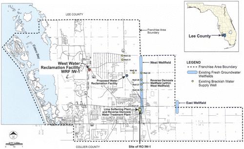
Data were collected from the Bonita Springs Utilities BWRO facility located in Bonita Springs, Florida (Fig. ). Data on the design of the facility were obtained from the original design report [Citation9] and from the operators and management of the facility. The geologic data from the well logs were obtained from the wellfield completion report [Citation10] and the deep geologic data and water quality from the testing of a deep-well used for concentrate disposal.
2.2. Monitoring data collected on wells used to obtain feed water
Data were collected from the utility operating staff on the pumping rates and totalized monthly production for all wells. Dissolved chloride measurements were obtained from the raw water pumped from each well at the end of each month of operation.
2.3. Analysis of pumping water quality data
The dissolved chloride data were plotted vs. time, and a linear regression was performed on the data. An equation linking the well pumping rate to the change of dissolved chloride concentration in time was obtained for each well. An analysis was performed to assess the projected change in salinity of the feed water to the BWRO plant based on the average current pumping rate of the wells over a 40-year period, and some additional analysis was conducted to assess higher pumping rates projected based on the utility population and overall water use projections. Salinity of the feed water (total dissolved solids (TDS)) being pumped from the wells was estimated using a standard ratio for dilute seawater as published by Goldberg et al. [Citation11]. The TDS concentration was estimated by dividing the dissolved chloride concentration values by 0.55 (standard ratio of dissolved chloride to TDS in average seawater is 19,000 mg/L/34,500 mg/L).
3. Results
3.1. Wellfield design, hydrogeology and aquifer description
Currently, the feed water required for the BWRO system is obtained from eight production wells tapping the Lower Hawthorn Aquifer. These wells are located along an irregular north-south alignment with well spacing ranging from 400 to 1,600 m (Fig. ). Construction details on the wells are given in Table . The overall wellfield yield is currently 30,700 m3/d, which is used to meet the 25,000 m3/d permeate capacity of the facility.
Table 1 Well numbers with construction details
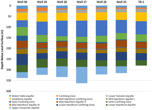
The production wells tap the Lower Hawthorn and Upper Suwannee aquifers as defined by Boggess [Citation12] and Missimer and Martin [Citation13]. A hydrogeologic section across the wellfield shows that there is some variability in the vertical position of the top of the production aquifer system (Fig. ). The section of the aquifer system open to the production wells ranges from 75 to 120 m in thickness. Muddy sediments within the Arcadia Formation form the upper confining unit of the aquifer system which is between 16 and 81 m in thickness. The lower confining unit occurs within the Suwannee Limestone and consists of muddy sediment facies located below the open-hole portion of the production wells. The thickness is likely less than 20 m based on the geologic log of the injection well used at the treatment plant for concentrate disposal [Citation14]. Based on the geology, the Lower Hawthorn/Upper Suwannee aquifer is a leaky or semi-confined aquifer system.
The aquifer coefficients play an important role in the reaction of the aquifer to pumping and in the pumping-induced long-term change in water quality. Aquifer performance tests were conducted onsite to measure the primary aquifer hydraulic coefficients [Citation10]. The average transmissivity across the wellfield is 1,540 m3/d. The average storativity of the aquifer is 2.3 × 10⁻⁴ and the average leakance is 1.9 × 10⁻⁴ d−1. The aquifer is deemed to be moderately to highly productive based on the transmissivity. It is well confined based on the low storativity and moderately leaky based on the leakance coefficient. Since the upper confining unit is much thicker compared to the lower confining unit, it is expected that the recharge to the wellfield will be predominantly from the bottom upwards. Therefore, the dissolved solids of the produced water will increase in time based on the water chemistry below the production aquifer.
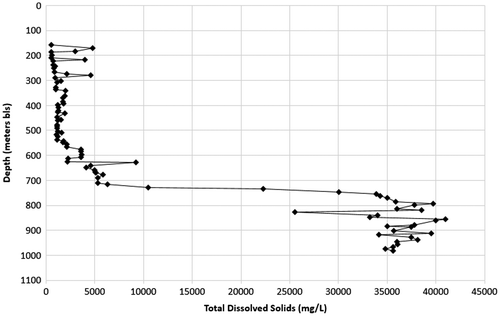
Water quality within the production aquifer varies somewhat at different well sites with the starting TDS concentration ranging from about 1,700 to 3,345 mg/L (Table ). Based on the water quality data collected during the deep test drilling for construction of the injection well at the site (Fig. ), the TDS concentration within the production aquifer at 244 m below surface is about 1,800 mg/L and appears to average about 2,100 mg/L to a depth of about 533 m below surface [Citation14]. It increases irregularly from 2,100 to about 3,500 mg/L from 533 to 610 m below surface. The TDS increases to an average of about 5,000 mg/L between 610 and 716 m below surface. Beginning at 716 m below surface, there is a rapid increase in TDS to 39,000 mg/L at about 790 m below surface. The change in TDS begins within the lower part of the Ocala Limestone which has a low to moderate hydraulic conductivity with the large increase occurring within the Avon Park Formation which has a very high hydraulic conductivity, likely associated with the sudden change in water quality.
Table 2 Dissolved chloride and TDS concentrations in the water from the production wells at the beginning of production, at the end of 2014, and projections to 40 years
3.2. Variation in feed water quality and pumping rates in time
Water quality within the Lower Hawthorn/Upper Suwannee aquifer system varies irregularly across the wellfield. The initial dissolved chloride concentrations show that the northernmost wells, 31 and 32, and well 28, located along the eastern alignment (Fig. ), had the lowest values. The highest initial salinities were found in wells 26 and 27, located in the southern part of the eastern alignment. There is no distinctive salinity pattern within the aquifer.
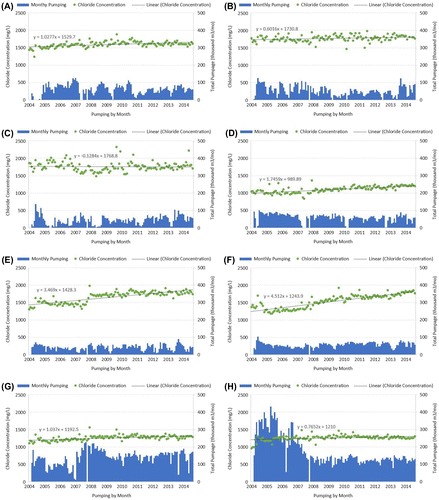
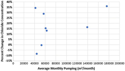
Over the 10-year period of operation, the highest increase in dissolved chloride change occurred in wells 29 and 30, which are located near the center of the wellfield, and in well 32, located at the northern extreme (Fig. ). Since the center of the wellfield tends to have the highest drawdown of the aquifer potentiometric surface, the highest change in salinity is correspondingly logical. The lowest rate of dissolved chloride change was found in wells 26 and 27 which showed only a slight change with the fitted regression line being nearly flat. These wells are located in the southern part of the wellfield. A plot of average monthly pumping rate from the wells vs. percentage change in dissolved chloride concentration for the 10-year operating period shows a poor correlation (Fig. ). The overall changes in dissolved chloride increase in the water produced from the wells during the 10-year operating period range from about −8 to +36%.
3.3. Use of a linear regression to predict the long-term water quality
The relationship between dissolved chloride concentration and monthly pumpage is linear. Therefore, projections of changes in groundwater salinity can be made by performing a linear regression on the data and extending the plot in time. The equations developed from the regressions on each well are shown in Fig. . These equations were used to estimate the changes in all of the wells using the current pumping rates beginning at the end of 2014 and extending 40 years forward in time (Table ). An assumption was made that no additional use of the production aquifer would be occurring within the projection period (exterior water users). Since the area within a few miles of the wellfield is highly developed, this is a reasonable assumption. Also, the wellfield will be expanded based on population projections for the Bonita Springs Utilities service area. Based on the linear nature of the pumping relation and salinity change in time, the slope may change to some degree in the future.
4. Discussion
4.1. Reasons for increased groundwater salinity with time: conceptual hydrogeologic model
The Lower Hawthorn/Suwannee aquifer is a leaky or semi-confined aquifer. Thickness of the confining strata above the aquifer is considerably greater than the confining strata below the aquifer. During pumping, the recharge to the aquifer is primarily upwards with some degree of enhanced lateral flow induced by the cone of depression at equilibrium. Therefore, the conceptual model of the aquifer should have the following properties: (1) the aquifer is a semi-confined system with solely upward pumping-induced recharge (insignificant downward recharge), (2) the aquifer and confining units above and below it are infinite in the x-y plan and the units have essentially equal thickness and hydraulic conductivity in the x-y direction, (3) no breaches of the confining unit nor significant changes in the hydraulic properties of the aquifer occur within the wellfield or the area of pumping influence, (4) the quality of water in the aquifer occurring below the production aquifer is the source of the higher salinity water and controls the upper limit of salinity change, and (5) no higher salinity source of water occurs within the up-gradient part of the aquifer that could cause an abrupt change of salinity within the production wells. A simplified diagram showing the general conceptual model is shown in Fig. .
Fig. 6. Conceptual model used to assess projected future water quality changes within the production aquifer.
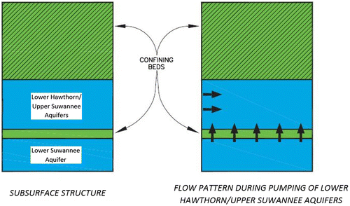
Based on the conceptual model, changes in water quality would be relativity slow based on the leakage of the aquifer and water quality would begin to take on the chemical characteristics of the underlying aquifer. Based on the rather uniform nature of the observed increase in feed water salinity from the individual production wells, the aquifer systems appears to be meeting the assumptions of the aquifer conceptual model. The controlling higher salinity within the wellfield area appears to be about 6,000 mg/L of dissolved chloride at a depth of 670 m below surface (Fig. ). This corresponds to a TDS concentration of about 11,000 mg/L.
The behavior of other BWRO facilities within southern Florida shows that the conceptual model shown applies to many other systems, but not all of them. The Island Water Association facility appears to operate with a similar conceptual model [Citation1,6], but the North Collier Utilities, Florida BWRO facility has a different conceptual model with a source of very high salinity water connected to the production aquifer either within the aquifer or well-connected to it from below [Citation1]. It is interesting to note that the western part of the North Collier wellfield has the salinity problem, while the eastern part of the wellfield operates similar to the Bonita Springs Utilities system. This facility is located about 20 km south of the Bonita Springs Utilities site and the wells are constructed into the same aquifer. Other BWRO facilities operating within 50 km of the Bonita Springs site, such as the City of Cape Coral, the City of Fort Myers, and the North Lee County BWRO facility, operate with a combination of different conceptual models and groundwater flow assumptions. Therefore, the Bonita Springs BWRO wellfield and the Lower Hawthorn/Upper Suwannee aquifer system must be considered at the end-member of high stability compared other facilities that exhibit greater feed water quality variation.
4.2. Impact of the long-term increase in feed water salinity on the BWRO design and operation
The rate of salinity increase of water from the production wells is known from the monitoring and shows a linear increase in time with a relatively low slope. Some roughness in the slope (e.g. stepped increase in production well no. 29) is likely caused by some water storage with the lower confining unit located below the well, and the overall variation of salinity within the wellfield is likely caused by variability in the flushing of connate water from some parts of the aquifer. However, the water quality changes based on the current pumping rates, overall and from individual wells, appear to allow a reasonable assessment to be made of the future trends in feed water that can affect the process operation based on the current pumping rates and projected future rates.
The design of the Bonita Springs Utilities BWRO plant is shown in Table and the process design is shown in Fig. . A key issue with regard to plant operation is the projected TDS of the feed water vs. the maximum TDS that the BWRO design can treat without changing the pumping pressure or the membranes. The current pumping rate of the wellfield is about 25,000 m3/d. The predicted TDS change based on the monitoring data over the next 20 years will bring the average TDS of the feed water to 3,611 mg/L. The maximum TDS of the feed water that can be treated is 8,129 mg/L. Therefore, it appears that long-term TDS increases in the feed water quality will not significantly affect the operation of the facility based on the current capacity.
Table 3 Bonita Springs BWRO plant specifications and characteristics
It is anticipated that the overall capacity of the BWRO treatment plant and the required feed water capacity may double over the next 20 years (Table ). The increase in wellfield capacity is planned with the addition of eight more production wells. The 16 production wells would allow operation of individual wells at a lower rate and would be used to stabilize any deviation of the water quality change based on the currently measured slopes of the changes observed in the production wells. It is likely that a solute transport model would be used in the future to assess optimum locations of new production wells to assure a future relatively stable water quality.
4.3. Future operational risk of abrupt feed water salinity changes
The greatest operational risk for any BWRO facility is the possibility that an abrupt change would occur in feed water quality that would exceed the capacity of the installed process to treat the water. Based on the observed salinity increase in the wellfield, it appears that the conceptual model showing relative uniformity in hydraulic characteristics and no extreme changes of water quality water within the production aquifer. Therefore, the likelihood of an abrupt change in water is minimal. Future expansion of the wellfield to meet projected increases in demand will need to be carefully planned to assure that a part of the aquifer system is used that continues to meet the general conceptual model.
4.4. Design risk and cost of retrofitting the BWRO process and water supply
When designing a BWRO facility using a groundwater source of feed water, there is always some risk that the feed water salinity will change to a concentration that cannot be accommodated by the process design. One method of mitigating the risk is to perform detailed groundwater modeling and analysis prior to the process design which would cost approximately $100,000 in addition to the standard hydrogeological design investigation. However, there is no guarantee that the modeling results will prove to be accurate within the 20 to 30 year time frame as recently pointed out by Maliva et al. [Citation15].
The second approach is to use a very conservative design that should accommodate an unanticipated salinity change. The cost on the front end of the facility is not high when the type of membrane used has a wide range in feed water salinities that can be treated. If the salinity rises above the maximum concentration (assume 10,000 to 12,000 mg/L in this case) that can be treated, there are two strategies that could be used to mitigate the issue. First, additional production wells could be added to reduce the impacts on the aquifer by spreading out drawdown impacts with a cost in this case of about $700,000 (four wells and pumps added and additional piping to produce acceptable water quality to the design expectancy of the facility of 30 years). If the process would have to be changed to install new, higher pressure membranes, the overall cost could rise to about $1,500,000 in this case to maintain the projected future permeate capacity to the life expectancy of the facility. These are rough estimates and assume that the water quality change is not extreme (e.g. would require seawater membranes).
5. Conclusions
All aquifers that are leaky to some degree and are used to produce feed water for BWRO facilities will show some long-term changes in water quality. Two key aspects of managing these facilities include knowing what changes can be expected in the future and how the changes may affect the operational reliability of the facility. Each BWRO facility is designed to be able to treat a specific range in feed water TDS based on the membrane type and the range of operation pressure that can be achieved using the installed high pressure pumps.
At the example facility, the maximum TDS feed water that can be treated based on the design of the facility is 8,129 mg/L. The initial average TDS of water from the wellfield was 1,354 mg/L which increased linearly to 1,570 mg/L over a 10-year operating period. Based on a regression analysis of each well, the projected average TDS from the wellfield should increase to 3,611 mg/L over the next 20 years based on the current pumping rate. Since there are some differences in the operational use of individual wells within the wellfield, the average water quality (TDS) of all wells does not exactly show the same characteristics of the feed water that enter the facility. However, it is within a few percent. Since the maximum TDS that is treatable using the current facility equipment is 8,129 mg/L, there should be no issue with water quality changes occurring within the useful life expectancy of the facility based on current pumping rates.
Future expansion of the BWRO capacity and consummate wellfield capacity must be carefully planned to maintain the general TDS increase rate. The water quality and pumping data collected from the wellfield show that the pumped aquifer reacts based on a conceptual model of a classic leaky aquifer with general uniformity in hydraulic characteristics and no breaches in confining units, nor extreme changes of production aquifer salinity within the influence area of the wellfield. The high quality of the data-set gathered to date will facilitate the development of a future solute transport model based on the current and proven conceptual model. Additional research on other BWRO facilities showing other aquifer conceptual models should be conducted for comparison to the one chosen herein to demonstrate the necessity to design facilities with sufficient the ability to treat feed water that has a greater future variability.
Acknowledgments
The authors thank the management and board of directors of Bonita Springs Utilities for providing data on the design of the BWRO facility and the monitoring data obtained from the production wells.
References
- T.M. Missimer, Water Supply Development, Aquifer Storage, and Concentrate Disposal for Membrane Water Treatment Facilities, second ed., Schlumberger Limited, Sugar Land, Texas, 2009.
- L.H. Motz, Lower hawthorn aquifer on Sanibel Island, Florida, Ground Water 20 (1982) 170–178.10.1111/gwat.1982.20.issue-2
- B.J. Peck, W.K. Martin, T.M. Missimer, Solute transport modeling of pumping-induced salinity changes in the upper Florida aquifer system, City of Cape Coral, Florida, in: Proceedings of the American Institute of Hydrology 1991 Annual Meeting and International Conference on Hydrology & Hydrogeology for the 90’s, Tampa, Florida, 1991, pp. 284–292.
- T.M. Missimer, Groundwater as a feedwater source for membrane treatment plants: Hydrogeologic controls on water quality variation with time, Desalination 98 (1994) 451–457.10.1016/0011-9164(94)00171-5
- A.O. Owosina, W.K. Martin, T.M. Missimer, Modeling of pumping-induced water quality changes in the upper Floridan aquifer at the North Collier County, Florida, wellfield, in: Proceedings of Biennial Conference and Exposition of the American Desalting Association, Monterey, California, August 4–8, 1996, 666–685.
- T.M. Missimer, S.A. Storves, Feedwater quality variation and the economics of water plant operation, The Island Water Association brackish-water RO treatment facility, Sanibel Island, Florida, in: Proceedings of the International Desalination Association World Congress on Desalination and Water Reuse, Manama, Bahrain, 2002, p. 13.
- T.M. Missimer, R.G. Maliva, I. Watson, Brackish-water desalination in Florida: Is the feed water from the Floridan Aquifer System a sustainable resource, in: Proceedings Florida Section of the American Water Works Association Annual Meeting, Orlando, Florida, November 30, 2014–December 3, 2014, p. 11.
- R.G. Maliva, D. Barnes, K. Coulibaly, W. Guo, W.S. Manahan, T.M. Missimer, Managing uncertainty in future water chemistry for brackish groundwater desalination systems, in: Proceedings International Desalination Association of the World Conference and Exhibition on Desalination and Water Reuse, San Diego, CA, August 30, 2015–September 4, 2015.
- CH2M-Hill, Schematic design report for Bonita Springs Utilities Reverse Osmosis Water Treatment Plant, Consultant’s report to Bonita Springs Utilities, Bonita Springs, Florida, 2001, p. 90.
- CH2M-Hill, Well completion report and hydrologic investigation for the Bonita Springs Utilities reverse osmosis test well system, Bonita Springs, Florida, Consultant’s report to Bonita Springs Utilities, Bonita Springs, Florida, 2002, p. 111.
- E.D. Goldberg, W.S. Broecker, M.G. Gross, K.K. Turekian, Marine Chemistry, in Radioactivity in the Marine Environment, National Academy of Sciences, Washington, DC, 1971, pp. 137–146.
- D.H. Boggess, Saline ground-water resources of Lee County, Florida, U.S. Geological Survey Open-File Report 74–247, 1974, pp. 62.
- T.M. Missimer, W.K. Martin, The hydrogeology of Lee County, Florida, in: T.M. Missimer, T.M. Scott (Eds.), Geology and Hydrology of Lee County, Florida, Florida Geological Survey Special Publication No. 49, 91–138, 2001.
- CH2M-HILL, Water Reclamation Facility Deep Injection Well Engineering Report, Consultant’s report prepared for Bonita Springs Utilities, Bonita Springs, Florida, 2004, p. 104.
- R.G. Maliva, D. Barnes, K. Coulibaly, W. Guo, W.S. Manahan, T.M. Missimer, Managing uncertainty in future water chemistry for brackish groundwater desalination systems, in: Proceedings of the International Desalination World Conference and Exposition on Desalination and Water Reuse, San Diego, California, September, 2015.

