Abstract
Folded patch antennas were investigated for the development of low-cost and wireless smart-skin sensors that monitor the strain in metallic structures. When the patch antenna is under strain/deformation, its resonance frequency varies accordingly. The variation can be easily interrogated and recorded by a wireless reader. The patch antenna adopts a specially chosen substrate material with low dielectric attenuation, as well as an inexpensive off-the-shelf radiofrequency identification (RFID) chip for signal modulation. Since the RFID chip harvests electromagnetic power from the interrogation signal emitted by the reader, the patch antenna itself does not require other (internal) power sources and, thus, serves as a battery-less (passive) and wireless strain sensor. In this preliminary investigation, a prototype folded patch antenna has been designed and manufactured. Tensile testing results show strong linearity between the interrogated resonance frequency and the strain experienced by the antenna. Through experiments, the strain sensing resolution is demonstrated to be under 50 μϵ, and the wireless interrogation distance is shown to be over a few feet for this preliminary prototype.
1.Introduction
Nearly one third of the 600,000 bridges in the US are steel bridges, for which fatigue-induced fracture/crack is among the most common concerns for inspectors and owners [Citation1,Citation2]. If cracks are not detected and repaired early, their growth may lead to expensive repairs or cause catastrophic failures. The current biennial bridge inspection mandated by federal highway administration (FHWA) is primarily a visual activity. Small-size cracks or cracks hidden under paint easily remain elusive to human eyes; the cracks may grow to critical and dangerous sizes before the next inspection cycle. Early detection of cracks for fracture-critical-members of steel bridges has long been an important and challenging issue in bridge health monitoring. Some current technologies, including metal foil strain gages, fiber optic sensors [Citation3], or ultrasonic testing [Citation4], may assist in crack monitoring. However, current sensing systems either require running lengthy cables in the structure [Citation5], or cover only very limited areas of the structure, or involve human-operated equipment that is not convenient for in situ continuous application. As a result, these technologies suffer from their high instrumentation and monitoring cost and are not practical for large-scale/large-area deployment and continuous monitoring in the field. As cracks are usually initiated by stress concentration, excessive stress/strain in ‘hot-spot’ areas can be monitored for early signs of fatigue and fracture.
Among many new technologies developed for structural health monitoring (SHM), wireless sensing has been widely explored in recent year [Citation6–9]. Compared to conventional cable-based systems, wireless systems have the advantage of significantly reducing instrumentation time and cost. An exhaustive review on wireless sensing for SHM can be found in [Citation10], which summarizes various academic and industrial wireless sensing devices that have been developed. The device usually contains an analog-to-digital converter for data sampling, a microprocessor for data processing, and a wireless transceiver for communication. Most of these devices operate on batteries and acquire data from associated traditional sensors. For example, strain measurement can be achieved by interfacing the wireless device with a metal foil strain gage, acceleration measurement can be achieved by interfacing the device with an MEMS (micro-electro-mechanical systems) accelerometer, etc. Overall, wireless technology is primarily utilized to transmit the digitized sensor data.
This research explores a different approach of exploiting wireless electromagnetic waves for strain sensing through the development of ‘smart skins’ made of radiofrequency identification (RFID)-enabled patch antennas [Citation11–15]. Instead of using wireless technologies to transmit digitized data, the strain-dependent behavior of the electromagnetic waves in the antenna is exploited as the sensing mechanism. The basic concept is that when a small piece of electric antenna (usually with 2D shape) is under strain/deformation, its electromagnetic resonance frequency may change accordingly. Such change can be interrogated by a wireless reader and used as the strain indicator. Jia et al. [Citation16] and Loh et al. [Citation17] developed inductively coupled wireless strain sensors to measure the shift of resonance frequency under tensile strain. The experimental results showed linearity between the resonance frequency shift and the strain. Andringa et al. [Citation18] and Chen et al. [Citation19] successfully developed corrosion sensors using the same inductive coupling concept. One drawback of inductively coupled sensors, however, is that the interrogation distance is usually limited, i.e. at a range around 10 cm. To overcome the limitations in interrogation distance, electromagnetic backscattering systems can provide an alternative [Citation20]. Tata et al. [Citation21] and Deshmukh and Huang [Citation22] developed microstrip patch antennas for measuring strain and detecting cracks in metallic structures. The unique sensor design in [Citation22] operates with a specially-devised light-activated radiofrequency (RF) switch, which requires an external circuit for the pseudomorphic high electron mobility transistor (pHEMT). The sensor operation needs direct line-of-sight for passing the switching light beam. In addition, Thomson et al. [Citation23] developed a radiofrequency cavity sensor, using a 25.4 mm diameter copper tubing with end plates as the strain sensing element. An external antenna needs to be connected with the cavity sensor for interrogation, and an interrogation distance of 8m is achieved by using high-gain antennas. The sensor is likely more suitable for embedment inside concrete than for installation on a steel surface, and tensile testing for strain measurement performance is not reported.
This paper presents an RFID-based folded patch antenna for measuring strain on the surface of metallic structures. The system utilizes the principle of electromagnetic backscattering and adopts a low-cost off-the-shelf RFID chip to reduce the design and manufacturing cost. The RFID-based technology allows the sensor to be passive, i.e. operate without other power source such as batteries [Citation24]. A special poly(tetrafluoroethylene) (PTFE) material with low dielectric attenuation is chosen as the antenna substrate, in order to improve the interrogation range through the enhancement of the antenna quality factor. Since the thickness of the sensor substrate is relatively large compared with conventional metal foil strain gages, simulation and experiments are performed to validate the strain transfer efficiency. Tensile testing experiments are conducted to validate the strain sensing performance of the prototype wireless sensor. Finally, the interrogation range of the prototype wireless system is investigated.
The rest of the paper is organized as follows. Section 2 first introduces the design and manufacturing of the wireless strain sensor, followed by the operation principle of the system. Section 3 presents the strain transfer simulation and experiments. Section 4 describes the experimental results from tensile tests and interrogation range tests for the prototype wireless sensor. Section 5 provides a summary and discussion of this work.
2. Wireless strain sensing system
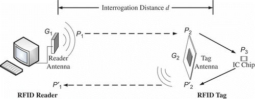
The operation of the wireless strain sensing system is based upon passive RFID technologies [Citation20]. The system consists of an interrogating RFID reader and an RFID tag (i.e. wireless strain sensor), where the tag includes an antenna and an integrated circuit (IC) chip (). The reader emits interrogation electromagnetic signal to the tag at power threshold P 1, so that the tag is activated and reflects signal back to the reader with power level P 1′. This reflection is also called backscattering. Section 2.1 introduces the RFID tag design and the basic sensing mechanism. Section 2.2 describes how to extract the resonance frequency data from the reader measurement.
2.1. RFID tag design
RFID IC chips usually have very small feature size and are inexpensive to produce. As part of the RFID tag, the functions of the IC chip are: (1) harvest the electromagnetic power from the interrogation signal emitted by the reader; (2) modulate the backscattered electromagnetic signal so that the signal can be properly recognized by the reader; (3) store a small amount of data that can be accessed and modified by the RFID reader. Although the third function is currently not exploited, it can be explored in the future for storing historic strain measurement data in the RFID tag.
The SL3ICS1002 chip (manufactured by NXP Semiconductors) was chosen as the RFID IC chip for this application. The low impedance of the chip is relatively easy to match during the tag antenna design. The chip contains 512 bits of memory for data storage, and a 64-bit tag identifier. In addition, reliable operation of multiple tags can be achieved through advanced anti-collision mechanism, which allows the reader to simultaneously access multiple RFID tags within the neighborhood. The broad frequency range of the chip (from 840 MHz to 960 MHz) allows international usage.
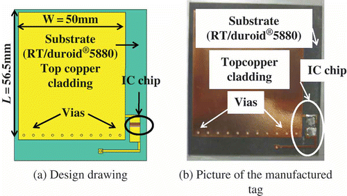
The design drawing and picture of the prototype RFID tag are shown in . Both the drawing and the picture illustrate the front/top side of the RFID tag, where the copper cladding (as part of the tag antenna) and IC chip are mounted on a 61 × 69 mm substrate. The back/bottom side of the tag is the electronic ground plane (also made of copper cladding) located on the back of the substrate. The thickness of the copper cladding at both sides of the substrate is 0.0178 mm (0.7 mil). The substrate material is Rogers RT/duroid®5880, a glass microfiber-reinforced PTFE composite with dielectric constant ϵr of 2.20 and thickness of 0.79 mm (31 mils). The RT/duroid®5880 material is adopted due to its low dielectric attenuation, which improves the interrogation range and the quality factor of the RFID tag. A thicker substrate enables a longer interrogation range, but reduces the strain transferred through the substrate (i.e. from the underlying structure, where the back of the substrate is bonded on, to the front-side copper cladding). This balance need be considered during the tag design. Vias through the substrate are used for connecting the top copper cladding with the ground plane on the back of the substrate, as well as connecting one pin of the IC chip with the ground plane.
The RFID tag design is based on a quarter-wave rectangular patch antenna (folded-patch) topology [Citation20]. The topology is chosen for its good radiation performance on top of metallic objects, and because it allows for 50% reduction to the footprint of a regular patch antenna. The antenna resonance frequency at zero strain level, f r, can be estimated as
where f
r
is the estimated resonance frequency, c is the speed of light, L is the physical length of the top copper cladding (56.5 mm), ϵ
r
is the dielectric constant of the substrate, ΔL is the additional electrical length compensating the effects due to the substrate thickness, substrate width, and the dielectric constant of the substrate. Using current design parameters as shown in , the initial resonance frequency can be estimated as 920.8 MHz according to EquationEquation (1)(1). When the antenna experiences strain deformation of ϵ in the longitudinal direction, the shifted resonance frequency becomes:
The equation shows that when strain ϵ is small, the resonance frequency changes approximately linearly with respect to strain. This linear relationship indicates that by measuring the antenna resonance frequency, the applied strain can be derived. This serves as the fundamental mechanism for the wireless strain sensing system.
2.2. Measurement of the resonance frequency
For the system shown in , assuming there is no obstacle between the reader and the tag, the power received at the tag antenna, P 2, can be approximated by the Friis free space formula [Citation25]:
where G 1 and G 2 are the gain of the reader antenna and tag antenna, respectively, d is the distance between the reader and the tag, λ is the wavelength of the interrogation electromagnetic signal emitted by the reader, c is the speed of light, and f is the interrogation frequency, i.e. the dominant frequency of the interrogation signal at one instant. The antenna gain is determined by the shape and dimension of each antenna.
Inside the RFID tag, the power is transferred from the tag antenna to the IC chip. This power transfer process is similar to the scenario of a battery (with its own internal resistance) powering an outside resistor. The power transfer is maximized only when the electrical impedance of the power source (i.e. the tag antenna in this application) conjugately matches the impedance of the load (i.e. the IC chip). When impedance mismatch occurs between the tag antenna and the chip, a portion of the power is reflected back from the chip to the tag antenna. The power reflection coefficient of the tag antenna, η, can be calculated as a measure of the reflected signal strength [Citation26]:
where ZLoad
and ZANT
represent the impedance of the chip and the tag antenna, respectively. Both impedance parameters are functions of the interrogation frequency f. The superscript “*” represents the conjugate of a complex number. Although the analytical form of η as a function of the interrogation frequency f is in general difficult to obtain, reaches minimum when the interrogation frequency f is equal to the resonance frequency of the tag antenna.
As a result of the impedance matching, the relationship between the power transmitted by the tag antenna, P
2, and the power received at the chip, P
3, can be described by the power reflection coefficient :
The wireless sensor is classified as passive because the RFID tag does not require its own power supply, i.e. the tag receives its operation power entirely through the electromagnetic emission/illumination from the reader. The minimum operating power for the SL3ICS1002 chip is 0.03 mW (milliwatt, P IC), which is a constant irrelevant to the interrogation frequency in the UHF frequency range. For a certain interrogation frequency f, the power threshold of an RFID tag is defined as the minimum transmitted power P 1 required to activate the tag, so that the tag responds to the reader. At each reading frequency, a reader operating in power threshold mode can automatically adjust the transmitted power P 1 so that P 3 is just enough to activate the IC chip:
Substituting EquationEquation (6)(6) into EquationEquations (5)
(5) and (3), the transmitted power threshold can be obtained:
The RFID tag antenna has been designed in a way that when the interrogation frequency f is equal to the resonance frequency of the RFID tag, best impedance matching between the tag antenna and the IC chip occurs. Therefore, the least amount of power needs to be transmitted by the reader for activating the RFID tag, which means the transmitted power threshold plot P
1(f) (measured by the reader) achieves minimum value at the resonance frequency. When the antenna size changes, e.g. due to strain/deformation, the resonance frequency changes accordingly to (EquationEquation (2)
(2)), and the P
1(f) plot for the antenna under strain reaches minimum at
.
In this study, the Tagformance RFID reader (manufactured by Voyantic) was adopted. The reader can interrogate an RFID tag at different frequencies and automatically measure the transmitted power threshold at each interrogation frequency. Other researchers in radiofrequency identification have also used this reader to measure the frequency behavior of RFID tags [Citation27–29]. The Tagformance reader can sweep through an extended interrogation frequency range from 800 to 1000 MHz. At default factory setting, the P 1(f) plot provided by the reader can achieve 0.1 MHz resolution in frequency sweeping and 0.1 dBm resolution in power threshold measurement. Through a USB 2.0 port, a computer interface is used to operate and retrieve measurement data from the reader.
3. Strain transfer validation
Figure 3 illustrates the RFID tag mounted at the center of an aluminum specimen under tension. The wireless strain sensing performance is expected to be the same for either aluminum or steel, since both materials are good metallic conductors. Aluminum specimens are used for tensile testing because they are much easier to prepare compared with steel specimens. As described in Section 2.1, the sensing component of the RFID tag is the antenna, which consists of two layers of 0.0178 mm (0.7 mil) thick copper cladding located on the top and bottom surfaces of a 0.79 mm (31 mils) thick substrate, respectively. The copper cladding at the bottom surface is attached to the aluminum specimen using superglue. Both simulation and experiments are conducted to verify that the stress/strain field in the tensile specimen is properly transferred through the substrate to the copper cladding.
3.1. Numerical simulation
The dimensions and material properties of the aluminum specimen, the tag substrate, and the copper cladding used for the prototype wireless strain sensor are listed in . Exploiting the symmetry of the problem, a finite element model for one quarter of the initial structure in was built in ANSYS software. Since the thickness of the superglue is small compared with the thicknesses of copper cladding and the substrate, the weakening effect to strain transfer by the superglue is neglected. Under this consideration, the superglue between the bottom copper cladding and the aluminum specimen is omitted in the simulation model, i.e. the bottom copper cladding elements and the neighboring aluminum elements share the same interface nodes in the finite element model. Similarly, the bonding between the copper cladding and the tag substrate is assumed to be ideal, i.e. the elements representing both top and bottom copper cladding layers share same nodes with neighboring substrate elements.
Table 1. Dimensions and material properties
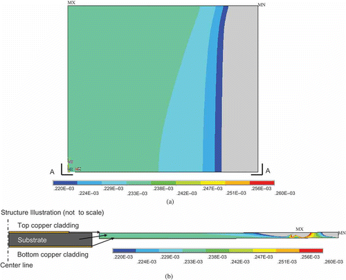
illustrates the plan view of the ANSYS meshing of the quarter model. High-resolution elements describing one quarter of the RFID tag, including the substrate and two layers of copper cladding, is located in Area 1 (lower-left of the figure). Under the RFID tag, elements describing one quarter of the aluminum specimen occupy all three areas in the figure. A 20-node element type is used in Area 2 for transiting between the high-resolution Area 1 and lower-resolution Area 3. Symmetric boundary condition is assigned to the left and lower edges of the model, and free boundary condition is assigned to the upper edge. Uniformly distributed load is applied at the right edge along the longitudinal direction.
Figure 4. Meshing of the quarter ANSYS model for mechanical simulation (Area 1: one quarter of the RFID tag; Areas 1, 2, and 3 combined: one quarter of the aluminum specimen).

The tensile load was adjusted so that 250 μϵ strain is generated around Area 1 in the aluminum. shows the corresponding axial strain distribution on the top-layer copper cladding. The axial strain on the copper cladding is reasonably uniform, i.e. the strain variation around the central area of the copper cladding is small. shows the axial strain distribution of the RFID tag in side view A–A. Since only one quarter of the structure is modeled, the left side of the strain distribution plot in corresponds to the center of the RFID tag, and the right side corresponds to the edge. The strain near the center area is very uniform across the two copper cladding layers and the substrate, yet the strain near the edge shows more variation. At the center of the copper cladding, the strain level is approximately 233 μϵ, which is fairly close to the 250 μϵ strain in the aluminum specimen. If the average strain is calculated by the total displacement between the two edges of the copper cladding, the axial strain is around 223 μϵ, which is 89.3% of the strain applied to the aluminum specimen. As a conclusion, the simulation results illustrate that with current substrate material, a significant portion of the strain in the aluminum specimen is properly transferred to the top surface of the tag substrate. This allows the size of the RFID antenna to change accordingly with the stress field in the specimen, and consequently, result in the resonance frequency change of the RFID tag.
3.2. Strain transfer experiments
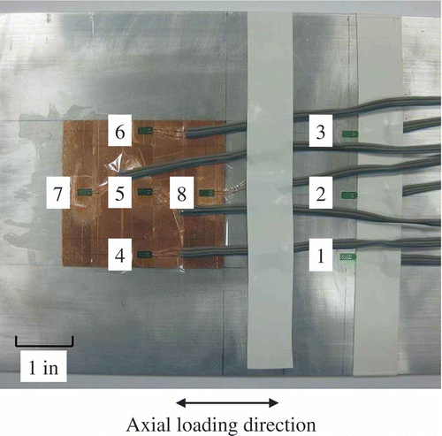
Laboratory experiments were also conducted to validate the strain transfer from the aluminum specimen to the top of the RFID tag. is a picture taken for the center area of the specimen, showing eight metal foil strain gages (FLA-2-23-3LT, Texas Measurements, Inc) installed. Three strain gages (#1–#3) are installed directly on the aluminum, for measuring the axial strain. Another five strain gages (#4–#8) are installed on top of the RFID tag, for measuring the axial strain transferred to the copper cladding. A National Instruments strain gage module (NI 9235), in combination with a CompactDAQ Chassis (NI cDAQ-9172) is used for collecting strain gage data. Tensile testing is conducted using a 22-kip SATEC machine.
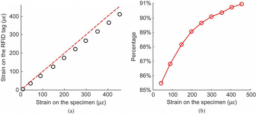
Figure 7a shows the measurement data from the strain gages. Starting from zero strain to 450 μϵ, 10 strain levels are measured at increments of approximately 50 μϵ. For every data point, the horizontal-axis value is the average measurement among strain gages #1–#3; the vertical-axis value is the corresponding average measurement among gages #4–#8. A 45° reference line is drawn on the plot. At each strain level, the difference between horizontal and vertical-axis values is relatively small. shows the percentage of the strain transferred from the aluminum specimen to the copper cladding, calculated as the ratio of the vertical-axis value over the horizontal-axis value for each data point in . The strain transfer percentage varies from 85.5% to 91%, and the percentage at 250 μϵ closely matches the ANSYS simulation. This shows that the tag antenna size changes proportionally to the strain in the aluminum specimen, which can enable a corresponding resonance frequency shift in the wireless strain sensor. The variation in strain transfer percentage at different strain levels is likely due to the effect of the superglue nonlinearity, coupled by the relatively large area that the superglue needs to be applied. Improvement to the strain transfer consistency will be performed in the future. For example, reducing the thickness and plane dimension of the RFID tag has the potential to improve the reliability of strain transfer.
4. Validation experiments for the wireless strain sensor
To validate the performance of the wireless strain sensor, tensile tests were performed at two different interrogation distances (12 in. and 24 in.). The tensile testing results are presented in Section 4.1. Effects of interrogation distances to resonance frequency are further analyzed in Section 4.2.
4.1. Tensile testing results
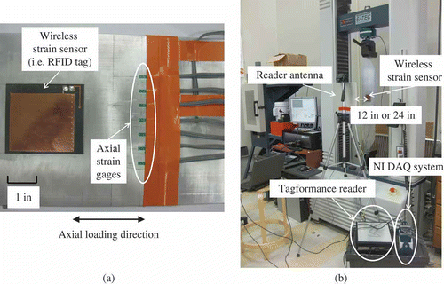
Figure 8a shows the center area of the specimen, with the wireless strain sensor and seven conventional strain gages (FLA-2-23-3LT, Texas Measurements, Inc.) measuring the axial strain. shows the experimental setup for the tensile testing with a 22-kip SATEC machine. The reader antenna is mounted on a tripod, facing the wireless strain sensor at a distance of 12 in. or 24 in. The relationship between the resonance frequency of the sensor and the applied strain is quantified at these two different interrogation distances in order to better understand the relationship between strain, resonance frequency and distance. Through a coaxial cable, the reader antenna is connected with the Tagformance reader, which communicates with a laptop through USB 2.0. A National Instruments strain gage module (NI 9235), in combination with a CompactDAQ Chassis (NI cDAQ-9172), is used for collecting data from conventional strain gages.
Figure 8. Experimental setup for the tensile tests. (a) Picture of the sensor instrumentation for wireless sensing experiments. (b) Picture of the wireless strain sensing experiments.
4.1.1. Testing results at 12 in. interrogation distance
Tensile testing was first conducted for 12 in. interrogation distance. The force applied by the testing machine was configured so that approximately a 150 μϵ increment is achieved at each loading step. The average interrogation power threshold in dBm scale, , is measured by the Tagformance reader at each loading step. Assuming P
1 is the power threshold in mW, the conversion to dBm scale is defined as
To reduce the effect of measurement noise, a total of five measurements is taken for each strain level and the average is calculated at every interrogation frequency f:
where is the average transmitted power threshold in dBm,
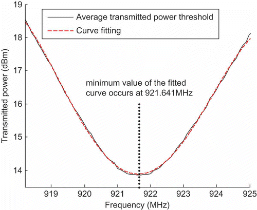
is the transmitted power threshold in dBm from the ith measurement. For example, the average transmitted power threshold at zero strain level is plotted as the solid line in . As described in Section 2.2, the transmitted power threshold reaches its minimum value at the resonance frequency. Since the valley area of the plot is relatively flat, the precise resonance frequency is not obvious. To resolve this difficulty, a fourth order polynomial curve fitting is performed to the valley area, which is shown as the dashed line in . The value of the fitted fourth order polynomial is evaluated at a frequency step of 0.001MHz, and the resonance frequency (for zero strain level) is identified as 921.641 MHz using the fitted polynomial.
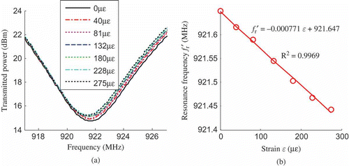
Figure 10a shows the average transmitted power threshold plot, , for different strain levels. The strain levels are calculated as the average among the seven axial strain gages and then corrected by the strain transfer percentages shown in . Using the method described in , for each strain level, a fourth order polynomial curve fitting is conducted. The frequency corresponding to the minimum value of the fitted polynomial is determined as the resonance frequency f
r′, which is plotted in against the strain level.
Figure 10. Tensile testing results for the ∼150 μϵ/step loading case at 12 in. interrogation distance. (a) Average transmitted power threshold . (b) Resonance frequency f
r′ versus strain ϵ.
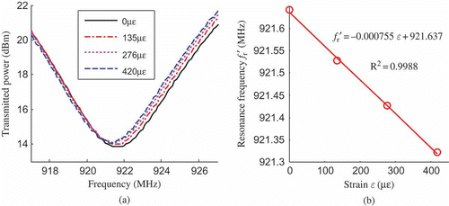
In addition, linear regression is conducted to the four data points in . The slope coefficient, –0.000755 MHz/μϵ (i.e. –755 Hz/μϵ), is the strain sensitivity of the wireless sensor, which means that 1 μϵ increment on the specimen causes 755 Hz decrease in the resonance frequency of the wireless strain sensor. The intercept, 921.637 MHz, is the resonance frequency of the wireless strain sensor at zero strain level. As described in Section 2.1, the theoretical resonance frequency of the sensor at zero strain level is 920.8 MHz. The relative difference between the theoretical and the experimental resonance frequencies is only 0.09%, which shows a very close match. According to EquationEquation (2)(2), the theoretical strain sensitivity is –920.8 Hz/μϵ. The difference between the analytical and experimental strain sensitivities is probably because the dielectric constant ϵ
r
(which is assumed constant in the analytical study) changes with respect to strain. Different from an ideal material, small voids always exist in the substrate. Distortion of the voids under strain can affect the dielectric constant. also shows the coefficient of determination, R2, from the linear regression [Citation30]. A value of R2 = 0.9988 indicates good linearity of the data.
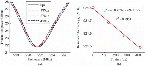
In order to explore the achievable strain resolution of the wireless sensor, the strain increment for each tensile loading step is reduced from ∼150 μϵ to ∼50 μϵ. All other experimental setup and analysis procedures are kept the same as before. The average transmitted power threshold for each strain level is plotted in , and the resonance frequency for each strain level is extracted and shown in . The strain sensitivity for this case is –771 Hz/μϵ (i.e. –0.000771 MHz/μϵ). This is reasonably close to the –755 Hz/μϵ sensitivity shown in . In addition to the possible change in the dielectric constant ϵ
r
, the small difference may also be attributed to the fact that according to EquationEquation (2)(2), the theoretical relationship between f
r′ and ϵ is only approximately linear. The difference between the intercepts in and can be due to the different initial conditions of the specimen upon being mounted to the testing machine by grips. Although the coefficient of determination in is slightly lower than that in , the linearity is still fairly acceptable.
4.1.2. Testing results at 24 in. interrogation distance
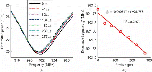
For the next series of tests, the distance between the reader antenna and the wireless strain sensor was increased to 24 in., while maintaining the relative orientation between the reader antenna and the sensor. All other experimental setup and analysis procedures remain the same as those in Section 4.1.1. shows the average transmitted power threshold for the ∼150 μϵ/step tensile tests, and shows the resonance frequency at each strain level. The strain sensitivity is –746 Hz/μϵ, which is very close to the sensitivity at 12 in. interrogation distance. Good linearity is also observed for the data in , which shows that the performance of the wireless strain sensor is still acceptable when the interrogation distance is 24 in. The experimental results for the ∼50 μϵ/step tensile tests at 24 in. interrogation distance are shown in . As expected, the linearity shown in is slightly worse than other cases, because the longer interrogation distance and higher requirement for strain resolution make the measurement more challenging. shows a strain sensitivity of -817 Hz/μϵ, which is higher than those in through . The outlier point at 0 μϵ in has obvious influence to the linear regression. If the regression is performed again without the outlier point, the slope (i.e. sensitivity) changes to –727 Hz/μϵ; this is more consistent with the other testing results.
4.2. Interrogation distance analysis
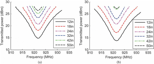
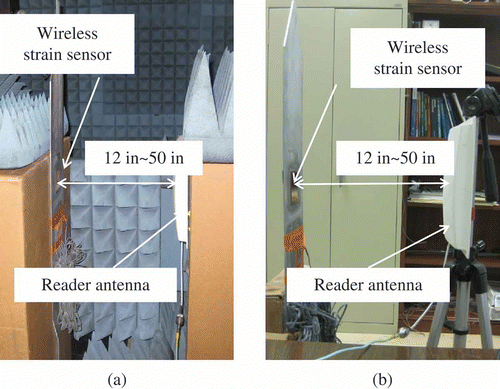
In order to investigate the largest interrogation distance that the prototype wireless system can provide, the wireless sensor under zero strain was tested with various interrogation distances. For comparison, the sensor is tested inside and outside an anechoic chamber, for which the experimental setups are shown in and , respectively. shows the average transmitted power threshold plots at different distances measured in the anechoic chamber, and shows the plots outside the chamber. For both scenarios, the distance varies from 12 in. to 50 in. The resonance frequencies at different distances are extracted and plotted in . The variation in the chamber is about 0.08 MHz, as shown in . For testing outside the chamber, as shown in , resonance frequency variation is of similar magnitude, except for the 50 in. case. The larger difference outside the chamber can be due to more multipath propagation of the electromagnetic wave, as well as more environmental noise. It should be noted that regardless of the resonance frequency variation at different interrogation distances, wireless strain sensing is feasible as long as the relationship between the strain and the resonance frequency remains approximately linear at a fixed interrogation distance. This has been demonstrated by the tensile testing results for 12 in. and 24 in. interrogation distances. Nevertheless, future research will continue exploring advanced design, interrogation, or analysis techniques for more constant resonance frequencies at different interrogation distances.
Figure 16. Resonance frequency f r (at zero strain level) extracted from the transmitted power threshold plots in . (a) Inside the anechoic chamber. (b) Outside the anechoic chamber.

5. Summary and discussion
This paper presents some preliminary investigation on the design, fabrication and experiments for an RFID-based passive wireless strain sensor utilizing folded patch antennas. Both analytical studies and tensile testing experiments demonstrate a strong linear relationship between the resonance frequency of the antenna and the strain experienced by the sensor. Not requiring battery power, the low-cost passive wireless strain sensor has the potential to offer large-scale dense deployment for civil structures. Compared with traditional metal foil strain gages, although the precision of this preliminary prototype is yet to be improved, the operation convenience enabled by the wireless/battery-less sensor may outweigh the disadvantage, particularly for scenarios where qualitative (rather than quantitative) measurements are sufficient.
Since the resonance frequency of the wireless strain sensor is determined by the size of the patch antenna, the footprint of the sensor will be significantly reduced in future studies by increasing the resonance frequency. In addition, longer interrogation distance can be achieved by adopting a high-gain antenna at the reader side, and the consistency of the resonance frequency at various distances needs to be improved. To further reduce the manufacturing cost of the wireless sensor, future research will also explore the approach of inkjet-printing silver nanoparticles onto organic substrates, where the printed nanoparticles can replace copper cladding and form an RFID antenna.
Acknowledgment
This material is based upon work supported by the Federal Highway Administration under agreement No. DTFH61-10-H-00004. Any opinions, findings, and conclusions or recommendations expressed in this publication are those of the authors and do not necessarily reflect the view of the Federal Highway Administration.
References
- 2009 . Report Card for America's Infrastructure , Reston, VA : American Society of Civil Engineers .
- 2009 . Manual of Bridge Evaluation , Washington, DC : American Association of State Highway & Transportation Officials .
- Zhou , Y. , So , R.M.C. , Jin , W. , Xu , H.G. and Chan , P.K.C. 1999 . Dynamic strain measurements of a circular cylinder in a cross flow using a fibre bragg grating sensor . Exp. Fluid , 27 : 359 – 367 .
- Mahmoud , A.M. , Ammar , H.H. , Mukdadi , O.M. , Ray , I. , Imani , F.S. , Chen , A. and Davalos , J.F. 2010 . Non-destructive ultrasonic evaluation of CFRP-concrete specimens subjected to accelerated aging conditions . NDT & E Int. , 43 : 635 – 641 .
- Çelebi , M. 2002 . Seismic Instrumentation of Buildings (with Emphasis on Federal Buildings) , Menlo Park, CA : United States Geological Survey . Report No. 0-7460-68170
- Straser , E.G. and Kiremidjian , A.S. 1998 . A Modular, Wireless Damage Monitoring System for Structures , Stanford, CA : John A. Blume Earthquake Engineering Center, Stanford University . Report No. 128
- Spencer , B.F. Jr. , Ruiz-Sandoval , M.E. and Kurata , N. 2004 . Smart sensing technology: opportunities and challenges . Struct. Control Health Monit. , 11 : 349 – 368 .
- Lynch , J.P. , Law , K.H. , Kiremidjian , A.S. , Carryer , E. , Farrar , C.R. , Sohn , H. , Allen , D.W. , Nadler , B. and Wait , J.R. 2004 . Design and performance validation of a wireless sensing unit for structural health monitoring applications . Struct. Eng. Mech. , 17 : 393 – 408 .
- Wang , Y. , Lynch , J.P. and Law , K.H. 2007 . A wireless structural health monitoring system with multithreaded sensing devices: design and validation . Struct. Infrastruct. Eng. , 3 : 103 – 120 .
- Lynch , J.P. and Loh , K.J. 2006 . A summary review of wireless sensors and sensor networks for structural health monitoring . Shock Vib. Digest , 38 : 91 – 128 .
- Li , S. , Visich , J.K. and Khumawala , B.M. 2006 . Radio frequency identification technology: applications, technical challenges and strategies . Sensor Rev. , 26 : 193 – 202 .
- Rao , K.V.S. , Nikitin , P.V. and Lan , S.F. 2005 . Antenna design for UHF RFID tags: a review and a practical application . IEEE Trans. Antenn. Propag. , 53 : 3870 – 3876 .
- Yang , L. , Rida , A. , Vyas , R. and Tentzeris , M.M. 2007 . RFID tag and RF structures on paper substrates using inkjet-printing technology . IEEE Trans. Microw. Theor. Tech. , 55 : 2894 – 2901 .
- Rida , A. , Yang , L. and Tentzeris , M.M. 2010 . RFID-Enabled Sensor Design and Applications , Norwood, MA : Artech House .
- Garg , R. , Bhartia , P. , Bahl , I. and Ittipiboon , A. 2001 . Microstrip Antenna Design Handbook , Norwood, MA : Artech House .
- Jia , Y. , Sun , K. , Agosto , F.J. and Quinones , M.T. 2006 . Design and characterization of a passive wireless strain sensor . Meas. Sci. Tech. , 17 : 2869 – 2876 .
- Loh , K.J. , Lynch , J.P. and Kotov , N.A. 2008 . Inductively coupled nanocomposite wireless strain and pH sensors . Smart Struct. Syst. , 4 : 531 – 548 .
- Andringa , M.M. , Neikirk , D.P. , Dickerson , N.P. and Wood , S.L. 2005 . Unpowered wireless corrosion sensor for steel reinforced concrete , Proc. IEEE Sensor .
- Chen , Y. , Munukutla , S. , Pasupathy , P. , Neikirk , D.P. and Wood , S.L. 2010 . Magneto-inductive waveguide as a passive wireless sensor net for structural health monitoring , Proc. SPIE .
- Finkenzeller , K. 2003 . RFID Handbook , New York : Wiley .
- Tata , U. , Huang , H. , Carter , R.L. and Chiao , J.C. 2009 . Exploiting a patch antenna for strain measurements . Meas. Sci. Tech. , 20 : 015201
- Deshmukh , S. and Huang , H. 2010 . Wireless interrogation of passive antenna sensors . Meas. Sci. Tech. , 21 : 035201
- Thomson , D.J. , Card , D. and Bridges , G.E. 2009 . RF cavity passive wireless sensors with time-domain gating-based interrogation for SHM of civil structures . IEEE Sensor J. , 9 : 1430 – 1438 .
- Philipose , M. , Smith , J.R. , Jiang , B. , Mamishev , A. and Roy , S. 2005 . Battery-free wireless identification and sensing . IEEE Pervasive Comput. , 4 : 37 – 45 .
- Balanis , C.A. 1997 . Antenna Theory: Analysis and Design , New York : John Wiley and Sons Inc .
- Kurokawa , K. 1965 . Power waves and the scattering matrix . IEEE Trans. Microw. Theor. Tech. , 13 : 194 – 202 .
- Merilampi , S.L. , Björninen , T. , Vuorimäki , A. , Ukkonen , L. , Ruuskanen , P. and Sydänheimo , L. 2010 . The effect of conductive ink layer thickness on the functioning of printed UHF RFID antennas , Proc. IEEE .
- Björninen , T. , Merilampi , S. , Ukkonen , L. , Sydänheimo , L. and Ruuskanen , P. 2009 . “ The effect of fabrication method on passive UHF RFID tag performance ” . In Int. J. Antenn. Propag 920947
- Bhattacharyya , R. , Floerkemeier , C. and Sarma , S. 2009 . Towards tag antenna-based sensing utilizing ordinary RFID tags , Orlando, , USA : IEEE RFID 2009 Conference .
- Chatterjee , S. and Hadi , A.S. 1986 . Influential observations, high leverage points, and outliers in linear regression . Stat. Sci. , 1 : 379 – 416 .
