
ABSTRACT
This paper extends to composite plates including piezoelectric plies the variable kinematics plate modeling approach called Sublaminate Generalized Unified Formulation (SGUF). Two-dimensional plate equations are obtained upon defining a priori the through-thickness distribution of the displacement field and electric potential. According to SGUF, independent approximations can be adopted for the four components of these generalized displacements: an Equivalent Single Layer (ESL) or Layer-Wise (LW) description over an arbitrary group of plies constituting the composite plate (the sublaminate) and the polynomial order employed in each sublaminate. The solution of the two-dimensional equations is sought in weak form by means of a Ritz method. In this work, boundary functions are used in conjunction with the domain approximation expressed by an orthogonal basis spanned by Legendre polynomials. The proposed computational tool is capable to represent electroded surfaces with equipotentiality conditions. Free-vibration problems as well as static problems involving actuator and sensor configurations are addressed. Two case studies are presented, which demonstrate the high accuracy of the proposed Ritz-SGUF approach. A model assessment is proposed for showcasing to which extent the SGUF approach allows a reduction of the number of unknowns with a controlled impact on the accuracy of the result.
1. Introduction
Composite structures with embedded or bonded piezoelectric sensors and/or actuators are among the most indicated solutions for implementing an adaptive strategy for, e.g., vibration suppression applications [Citation1]. The design and implementation of such structures faces two contrasting requirements. On the one hand, it is very important for a reliable design to have the possibility of accurately predicting the global and local electromechanical response of the structure [Citation2]. On the other hand, a computationally efficient procedure is necessary, for instance in the framework of optimization procedures [Citation3] or in the control algorithm for allowing a real-time adaptation [Citation4]. The three-dimensional (solid) elements with piezoelectric coupling currently available in commercial finite element software provide an excessively cumbersome computational framework, therefore much effort has been dedicated to the formulation of accurate reduced-order models, as witnessed by the early review papers [Citation5,Citation6] and by the more recent developments [Citation7–Citation12].
Unified formulations, pioneered by Reddy [Citation13] and systematically developed by Carrera [Citation14], allow constructing within a single computer program a variable-kinematics modeling approach with variable accuracy and computational cost, see also [Citation15]. The importance of such an approach, in particular for coupled multi-field problems such as composite structures with piezoelectric elements, was early recognized [Citation16–Citation19]. Carrera Unified Formulation (CUF) was subsequently generalized by Demasi [Citation20] (Generalized Unified Formulation, GUF). D’Ottavio [Citation21] further extended the flexibility of GUF to include a sublaminate approach (SGUF): in SGUF, the composite stack is subdivided into an arbitrary number of laminates grouping adjacent physical plies, and a GUF variable-kinematics model can be employed for each sublaminate independently. Recently, the authors employed the displacement-based SGUF approach in conjunction with a Ritz method previously developed by Dozio and Carrera [Citation22]: mechanical problems involving bending, buckling and free-vibration, including visco-elastic layers, have been addressed [Citation23–Citation25]. The proposed Ritz method is particularly useful as it provides sufficient flexibility for a rapid analysis of configurations involving arbitrary boundary and loading conditions as well as anisotropic coupling.
This paper presents the extension of the Ritz-SGUF approach to composite plates with piezoelectric plies working in extension mode (31-mode). The resulting computational tool is based on Hamilton’s principle involving the displacements and the electric potential as primary field variables. It accounts for the presence of electroded interfaces and verifies exactly the related equipotentiality conditions, which are known to play a major role for a realistic determination of the electro-mechanical coupling associated to the piezoelectric response [Citation26].
The paper is organized as follows. The modeling approach is outlined in Section 2, where the compact index notation typical of Unified Formulations and the adopted Ritz solution are presented up to the derivation of the discrete algebraic system to be solved. Section 3 reports results obtained for representative case studies: the electro-mechanical coupling coefficients is investigated for various boundary conditions in Section 3.1, a static analysis with actuator and sensor configurations is carried out in Section 3.2, and the modeling flexibility of the SGUF approach is illustrated by referring to a double sandwich plate with piezoelectric plies in Section 3.3. Finally, Section 4 summarizes the main conclusions and suggests the direction for further work.
2. Modeling approach
2.1. Description of the geometry
A plate is considered that occupies the volume , where
is the constant thickness and
is the reference surface lying on the
plane. The composite plate is composed of
homogeneous plies stacked along the thickness direction
, each of thickness
, see . According to the SGUF approach, the laminate is subdivided into
sublaminates, each of constant thickness
and consisting of a stack of
adjacent plies. Throughout the paper, indexes
and
are related to the physical plies and the sublaminate, respectively, and quantities related to the ply
of the sublaminate
will be indicated by
. Local coordinates
and
are introduced along with the corresponding non-dimensional coordinates
Figure 1. SGUF: geometry description and employed coordinates across the thickness.
These coordinates are linked through the relation
where and
are the midplane
coordinates of the ply and sublaminate, respectively.
2.2. The variational approach based on generalized displacements
The two-dimensional (2D) model of the composite piezoelectric plate is obtained upon introducing a priori assumptions for the through-the-thickness behavior of the displacements and the electrostatic potential
in a variationally consistent manner. Unless otherwise stated, Latin indexes range in
while Greek indexes take values in
. Adopting tensor notation and the repeated index summation convention, the weak form of the mechanical and electrical equilibrium equations is expressed by the following integral statement
where ,
,
and
represent the strain and stress tensors and the electric field and electric displacement vectors, respectively,
is the mass density,
indicates an admissible virtual variation,
is the vector of external traction imposed at the boundary
and
is the imposed electric charge density imposed at the boundary
. In this paper it shall be assumed without loss of generality that mechanical load and electric charge densities are imposed at the top and/or bottom surfaces of the plate, viz.
, while essential boundary conditions specifying displacements and electric potential are defined at
. Eq.(2) can be hence re-expressed upon separating in-plane and through-the-thickness integrals and introducing the definition of sublaminates:
The variations in Eq.(2) and Eq.(3) are to be taken under the following subsidiary conditions:
• the linearized gradient relations for small perturbations:
where the notation stays for partial derivative with respect to
.
• the piezoelectric constitutive equations in each ply:
where is the stiffness coefficient at constant electric field,
the dielectric coefficient at constant strain and
the piezoelectric stress coefficient. Elastic plies are represented by Eq.(5) with nil piezoelectric coupling, i.e.,
. Voigt compact notation is introduced based on the symmetry of the strain and stress tensors according to
and
[Citation27]. Eq.(5) is thus expressed in terms of vectors and matrices as:
where uppercase Latin indexes . Note that Eq.(5) and Eq.(6) are considered to hold in the global Cartesian reference frame employed for describing the plate geometry, i.e., the relations include the angle
describing the orientation of the principal material axis
with respect to the structural axis
, see also [Citation27].
Note that the electric field is considered to be quasi-static compared to the mechanical wave propagation velocity.
2.3. Variable kinematics modeling in SGUF
Following the SGUF approach, each sublaminate is associated to a specific kinematic approximation, which is here extended for including the approximation for the electric potential . According to the compact index notation used in Unified Formulations, the generalized displacements are regrouped in one vector
In SGUF, the variation along the thickness direction of each unknown function
is defined by a polynomial expansion of order
and by specifying whether the
plies of the sublaminate are described in an Equivalent Single Layer (ESL) or Layer-Wise (LW) manner. Therefore, the plate model is expressed in SGUF notation as
where for a displacement component and
for the electric potential, see Eq.(7). The thickness functions
are expressed in terms of the ply-coordinates
if the plies of the sublaminate are described in a LW description; the approximation for the whole sublaminate is then obtained through the assembly of all plies upon enforcing the continuity of the function
at the interface between adjacent plies. However, if an ESL description is adopted for the sublaminate
, the thickness functions vary along
and the ply index
can be omitted in Eq.(8). If a constant approximation is used for a variable
within a sublaminate, one has
and
. If a linear approximation is used,
and the thickness functions correspond to the linear Lagrange polynomials that interpolate the values at the top and bottom of the ply (LW) or sublaminate (ESL). Higher-order approximations with
are implemented through a hierarchic enrichment of the polynomial basis and employ Legendre polynomials. More details can be found elsewhere [Citation21,Citation23].
In a sublaminate whose plies are described in an ESL manner, a slope discontinuity can be introduced in the kinematics at the interface between adjacent plies by superposing a Zig-Zag function to the
polynomial expansion given by Eq.(8). The Zig-Zag function employed in SGUF is a modification of the classical Murakami’s ZigZag Function (MZZF) [Citation28] such that it vanishes at the top and bottom planes of the sublaminate:
This way, the continuity conditions to be imposed between adjacent sublaminates for building the matrices for the whole composite stack involve only the unknown displacements corresponding to the top and bottom of each sublaminate.
2.4. Ritz approximate solution
The weak form solution of the two-dimensional problem is sought within the space spanned by the global approximation (Ritz) functions, which can be expressed as
A map between the physical plane and the computational
domain is introduced, where
. Furthermore, separation of the in-plane variables is invoked thus expressing the
th two-dimensional Ritz function as the product of two one-dimensional (‘beam’) functions:
where ,
(note that
and
may be, in general, different) and the relation between the
th function and the beam functions
and
has been chosen as
. Various sets of Ritz functions can be used; adopting orthogonal polynomials along with boundary functions allows to efficiently handle various boundary conditions, such as clamped, free or simply-supported edges, as well as to provide stable solutions for high values of
[Citation22]. This work employs Legendre polynomials for spanning the field solution in conjunction with boundary functions for imposing the essential boundary conditions at the edges:
where for the employed functions are
The boundary conditions on the displacements can thus represent clamped, free or simply-supported edges, while those on the electric potential
can describe a grounded edge (
) or an edge at which the potential is let free.
As far as the electric boundary conditions are concerned, the present implementation is also capable to cope with a prescribed distribution , which is imposed at an arbitrary interface
. For this, the through-thickness model must be chosen so that a through-thickness DOF will be associated to the considered surface, which is straightforward within the sublaminate approach and a LW description: indeed, with reference to Eq.(8), one has to satisfy
in order to have
. For this variable, the Ritz approximation in Eq.(10) is then simply replaced by a one-term expression for the prescribed distribution
. Electroded surfaces with a constant electric potential or a particular distribution of an applied electric potential are thus exactly represented as essential boundary conditions. It is worth noticing that only the essential boundary conditions are exactly satisfied by prescribing the values for the generalized displacements
, while the conditions on the electro-mechanical fluxes (stresses and electric displacements) are let free to be satisfied in weak sense.
2.5. The discrete system
The weak form of the equilibrium equation is formally expressed in terms of the generalized displacements by substituting Eq.(4) into Eq.(6), and both into Eq.(3). The through-the-thickness approximation and the Ritz solution are then introduced for the virtual and actual field variables according to following notation:
where according to Eq.(7),
and
according to Eq.(8), and
according to Eq.(10). All integrals along
are explicitly carried out and are identified by the following notation:
In a similar manner, the in-plane integrals of the Ritz functions are evaluated according to the following notation:
The discrete expression of Eq.(3) can be finally written as
The left-hand side is the virtual internal work and includes the inertial terms, for which .
is one of the material parameters of Eq.(6) depending on the nature of the generic variables
and
:
• if , i.e.
and
, then
is an elastic stiffness coefficient;
• if and
, i.e.
and
, then
is a piezoelectric stress coefficient; analogously, if
and
, then
• if , i.e.
, then
is a dielectric permittivity coefficient.
The right-hand side represents the virtual work done by the external loading applied at given interfaces :
• for , a mechanical loading with a prescribed traction distribution
:
• for , an electrical loading with a prescribed charge distribution
After cycling over all indexes of the thickness assumptions, assembly over all plies
and sublaminates
, and finally cycling over all Ritz expansion indexes
, the following discrete system is obtained:
Electrical open-circuit and short-circuit conditions can be taken into account as detailed hereafter [Citation29]. The electric potential DOF are subdivided in ‘internal’ electric DOF and those associated to an electroded surface, denoted
. No electric charge is imposed in correspondance of the ‘internal’ electric potential DOF, which comprise the electric potential DOF at non-electroded (NE) surfaces also. These can hence be statically condensed out, which leads to the following discrete system:
where
In the short-circuit configuration (SC), one sets : the system to be solved is composed of only the first hyper-row of Eq.(18a) and its last hyper-row can be used to recover the electric charge vector within a post-processing step. In the open-circuit configuration (OC), one sets
: a further static condensation of the electric potential DOF at the electrodes is carried out, which transforms the first hyper-row of Eq.(18a) into
The electric potential DOF at the open-circuited electrodes are then obtained from the second hyper-row in a post-processing step.
Static problems are obtained by dropping out the time-dependency, while free-vibration responses are obtained by setting along with
and
, where
and
is the eigenfrequency.
3. Numerical results
Before proceeding to the presentation of some numerical examples, the naming convention is introduced for identifying the variable kinematics models that can be implemented. For each sublaminate, the in-plane displacements , the transverse displacement
and the electric potential can be described in an ESL (E) or LW (L) manner, and with a specific polynomial order
,
and
. These informations are gathered for each sublaminate
according to the following acronyms:
If a sublaminate does not host the electric potential variable , the corresponding index is dropped off. In fact, thanks to the sublaminate approach, the electric DOF can be retained only in those sublaminates with a piezoelectric response and omitted from those characterized by a merely elastic response.
For the whole stack of sublaminates, the acronyms are listed separated by a slash starting from the top sublaminate. For example, consider a composite layup subdivided into 3 sublaminates, all described by a FSDT kinematics; if the first (top) sublaminate is piezoelectric with a LW quadratic assumption for the electric potential, the second (central) sublaminate is purely elastic and the third (bottom) sublaminate is again piezoelectric with an ESL constant approximation for the electric potential, the resulting model is defined by the following acronym: .
3.1. Electromechanical coupling coefficients for a piezoelectric plate (T1)
This first case study, denoted as T1 and taken from [Citation30], aims at illustrating the capabilities of the proposed approach to handle different electro-mechanical boundary conditions. In fact, these are known to play a relevant role in the possibility of the structure to convert electric and deformation energy by means of the electro-mechanical coupling. The first five bending modes are considered of a freely vibrating moderately thick plate () made of 2 equally thick plies of PZT-5 material (data in ). The analysis is carried out in a two-dimensional plane strain setting. Four different sets of mechanical boundary conditions are considered at the plate edges
, which can be both simply-supported (SS), both clamped (CC), clamped-free (CF) and clamped-simply-supported (CS). The simple support condition amounts to set
. The interface
between the two plies is electrically grounded and different electrical conditions are applied to the top and bottom surfaces of the plate, which may be covered by a thin conducting electrode or let without electrode. The electrode is modeled as an equipotential surface without mechanical stiffness at which two electric conditions can be applied: a nil electric potential is imposed, which yields a short-circuit condition (SC), or the potential value is let free, which yields an open-circuit condition (OC). If no electrode is present (NE), the electric potential is let free to vary along
at the outer surfaces. In all cases, the vertical edges
are electrode-free. Krommer provides analytical solutions obtained with an FSDT model (with a shear correction factor of 5/6) for the SC and OC configurations [Citation30]. Further reference solutions are obtained by FEM computations with the commercial software Abaqus employing a mesh of 100
10 quadratic elements CPE8E.
Table 1. T1: Material data for the transversely isotropic PZT-5 material polarized along the direction. Superscripts
and
specify that the coefficients are given at constant electric field and at constant strain, respectively. Plate length
[m], thickness
[m].
Before proceeding further, it is useful to present a convergence study of the present Ritz solution. The first and the sixth circular eigenfrequencies are considered for a CC and a CF configuration. The electrical boundary conditions are the following: the mid-surface is electroded and grounded (), the bottom surface is electroded and in open-circuit (
free), the top surface is not electroded (NE). The results of the convergence study are reported in for a number of Ritz expansion terms
that range from 4 up to 64 (cylindrical bending is assured by
and
). The plate is modeled with an FSDT kinematics and a LW quadratic expansion of the electric potential, i.e., an
model. A shear correction factor of 5/6 is used. Based on the convergence analysis, an expansion order
will be used in the subsequent computations.
Figure 2. T1: Convergence analysis for first and sixth eigenfrequencies of the CC and CF plate.
– report the first 6 circular eigenfrequencies obtained by the present Ritz-SGUF approach for the four different mechanical boundary conditions. For each case, the three electrical configurations SC, OC and NE are considered. Two different models are used: the FSDT model (5/6 as shear correction factor) and the high-order
model. Note that both models retain a quadratic approximation for the electric potential in order to well capture the electric field induced by the piezoelectric coupling. The eigenfrequencies obtained by the plane strain solid Abaqus model are in perfect agreement with those of the more accurate model
model and are not reported in the tables for the sake of conciseness. Furthermore, the present
model identically recovers the analytical results obtained with the FSDT model by Krommer, whose numerical values can be found in [Citation30].
Table 2. T1: Circular eigenfrequencies [] for the hinged-hinged (SS) plate.
Table 3. T1: Circular eigenfrequencies [] for the clamped-clamped (CC) plate.
Table 4. T1: Circular eigenfrequencies [] for the clamped-free (CF) plate.
Table 5. T1: Circular eigenfrequencies [] for the clamped-hinged (CS) plate.
reports the ratio for the first 6 bending modes, where
is the eigenfrequency of the elastic plate when the piezoelectric coupling is neglected and
refers to the different configurations SC, OC and NE. illustrates the modal electro-mechanical coupling coefficient EMCC, defined as
, where
for electroded (equipotential) surfaces and
if a electric potential distribution can develop at the outer surfaces. A perfect match is obtained between the present results and those obtained by Krommer [Citation30] and with the solid Abaqus model. It is interesting to note that, despite the rather large differences between the eigenfrequencies
computed by the FSDT and
kinematics, see –, and show that the discrepancies in the frequency ratios
and
are small for the NE configuration and practically nil for the SC and OC configurations.
Figure 3. T1: Ratio between the eigenfrequencies of the piezoelectric plate and those of the equivalent elastic plate for different mechanical boundary conditions and electric circuits.
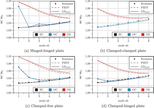
Figure 4. T1: Modal Electro-Mechanical Coupling Coefficient for different mechanical boundary conditions with and without equipotential electrode conditions.
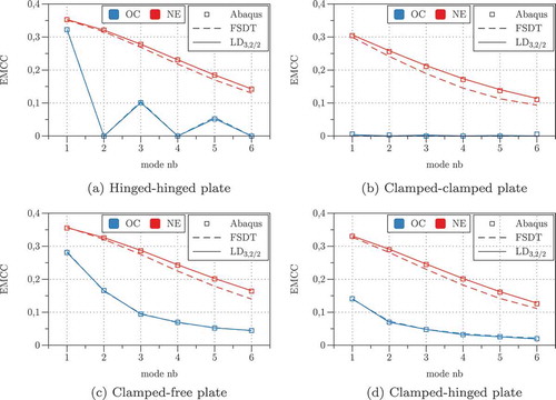
These results confirm the important role of the electro-mechanical boundary conditions on the coupled response of piezoelectric structures and the following comments can be made. shows the stiffening effect induced by the piezoelectric coupling for all considered electric boundary conditions. The largest increase is of about 10% and is obtained by the electrode-free configuration (NE configuration), while the SC configuration leads to the smallest increase. The stiffening effect of the SC configuration constantly increases from about 2.5% for mode 1 to about 4.5% for mode 6, irrespective of the mechanical boundary conditions. On the contrary, the stiffening effect associated to the NE and OC has its maximum for mode 1, with the NE configuration being alway stiffer than the OC configuration. As the mode number increases, the OC curve merge the SC curve, whereas the NE curve provides always slightly higher eigenfrequencies. The EMCC reported in directly quantifies the piezoelectric coupling effect. It is obvious that the NE configuration induces always a larger piezoelectric coupling than the OC configuration, an effect explained by the charge cancellation effect at the equipotential surface [Citation31]. The EMCC is maximum for the first mode and decreases for higher modes. Furthermore, statically determined (SS and CF) plates show a higher EMCC than those with more rigid end conditions (CC and CS). For the OC configuration (equipotential electrodes), the EMCC of the SS plate vanishes for modes with an even number of half-waves, and it is identically nil for the CC plate.
3.2. Static analysis of an orthotropic laminate with a piezoelectric ply (T2)
This second case study, identified as T2, is particularly interesting because Vel and Batra provided in [Citation32] reference 3D solutions for static actuator and sensor problems involving electro-mechanical boundary conditions different from the classical simply supported and electrically grounded edges.
The problem deals with a thick, square plate ( [m],
) consisting of a PZT-5A ply (thickness
) bonded on top of an elastic substrate composed of two Graphite-Epoxy (GrEp) plies (thickness
each). The non-zero coefficients of these materials are reported in . The fibers of the bottom GrEp ply are aligned with the
direction while those of the top GrEp ply are aligned with the
direction. The two edges
are simply-supported (
) and electrically grounded (
); at the edges
the two following sets of electro-mechanical boundary conditions are considered:
Table 6. T2: Material data for PZT-5A (transverse isotropy in plane) and for GrEp (transverse isotropy in
plane). Superscripts
and
specify that the coefficients are given at constant electric field and at constant strain, respectively.
SP configuration:
CD configuration:
Therefore, the edges are simply-supported and electrically grounded in the SP configuration and are clamped and electrically insulated in the CD configuration.
The interface between the elastic substrate and the piezoelectric ply is electroded and grounded while the bottom surface of the plate is traction-free. A sensor and an actuator configuration are considered, for which the boundary conditions at the top surface and the non-dimensional output quantities are defined as follows:
sensor configuration:
actuator configuration:
The coefficients employed for the non-dimensional quantities defined above are [GPa],
[
]
summarizes the reference values reported in [Citation32] with present solutions obtained by a quasi-3D model adopting an ED model for the piezoelectric ply, an LD
model for the elastic substrate and Ritz expansion orders
. The non-dimensional local response quantities defined in Eq.(20) (sensor configuration) and in Eq.(21) (actuator configuration) are reported for both, the SP and CD boundary conditions. For the SP boundary conditions, the present Ritz solution converges very rapidly (the reported values were already obtained with
) and exactly matches the analytical 3D solution. For the CD configuration the convergence is definitively slower, as already remarked by Vel and Batra [Citation32], due to the difficulty in satisfying the electric boundary condition of the insulated edges of the piezoelectric ply. Nevertheless, the present results are shown to well agree with the exact 3D solution even in the CD configuration.
Table 7. T2: Comparison between local non-dimensional response obtained with the quasi-3D model ED/LD
with
and the analytical 3D solution.
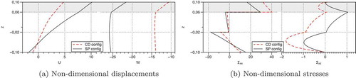
The influence of electro-mechanical boundary conditions is illustrated in for the sensor configuration and in for the actuator configuration. The through-the-thickness distributions are reported of the non-dimensional in-plane and transverse displacements and
() and )), as well as bending and shear stresses
and
() and )). The results are obtained with the quasi-3D model ED
/LD
with
.
Figure 5. T2-Sensor configuration: influence of the boundary conditions on the mechanical response of the PZT/GrEp laminate subjected to an external pressure load.
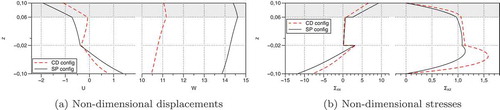
Figure 6. T2-Actuator configuration: influence of the boundary conditions on the mechanical response of the PZT/GrEp laminate under the action of an electric potential difference in the PZT ply.
Under the action of an external pressure load (sensor case), the in-plane displacement shows a strong zig-zag distribution, which is more accentuated for the CD boundary conditions than for the SP boundary conditions, see ) left. Due to the clamped edges, the CD configuration reduces the deflection of the plate () right) and, hence, the bending stress () left). This stress is largest at the outer surfaces
. The transverse shear stress
is quadratic in each ply and shows its maximum value within the bottom GrEp ply, whose fibers are oriented along the
axis ( right). This stress is approximately 1.5 times larger in the CD configuration than in the SP configuration.
In the actuator configuration, the zig-zag shape of the in-plane displacement is barely appreciable, see ) left. ) right shows that the transverse displacement is clearly non-constant across the plate thickness, with a rather steep linear variation across the piezoelectric actuator. Obviously, the clamped edges in the CD configuration reduce the deflection induced by the actuation. The through-thickness distribution of the bending stress , illustrated in ) left, is sensibly different from that of the sensor configuration: on the one hand, it shows its maximum values at the interfaces between the outer plies and the central GrEp ply, and not at the outer surfaces; on the other hand, the bending stress in the piezoelectric actuator is larger in the CD configuration than in the SP configuration. The transverse shear stress
is again quadratic in each ply and has its largest value within the bottom GrEp ply, but it shows an important peak also at the interface between the PZT ply and the elastic substrate.
A final comment is made concerning the fulfilment of the transverse stress boundary conditions at the top/bottom faces of the plate as well as their continuity at interfaces between dissimilar material plies, see the rightmost graphics of ) and ). Despite the present model is a displacement-based one, the high order expansion employed in each material ply (polynomials of degree 6) yields in fact very accurate solutions even for the transverse stress field, including the fulfilment of the natural boundary conditions. In order to satisfy these conditions with low-order models, one may consider the use of (partially) mixed formulations, see, e.g. [Citation33,Citation34].
3.3. Free-vibration analysis of a double sandwich plate with bonded piezoelectric plies (T3)
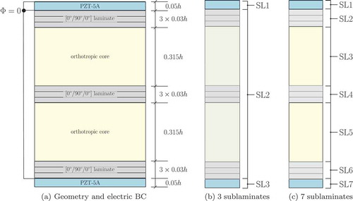
The third test case (T3) addresses the free-vibration response of an elastic substrate consisting of a double sandwich plate with two piezoelectric plies bonded at the top and bottom surfaces. The plate is square, of total thickness and simply-supported at its four edges. ) illustrates the composite stack and the electric boundary conditions: the double sandwich consists of two cores sandwiched between two composite laminates and separated by a third composite laminate; each composite laminate has three plies with stacking sequence [0/90/0]; the top surface as well as the interfaces between the elastic substrate and the piezoelectric plies are electroded and grounded, whereas the bottom surface is not electroded. The properties of the piezoelectric material (PZT-5A) correspond to those listed in , the mechanical properties of the core and face ply materials are listed in . This configuration, taken from Kapuria and Nath [Citation35], is here employed for highlighting how the proposed SGUF approach can optimize the number of DOF for reaching a desired accuracy. For this, models for the whole stack will be first proposed without resorting to the definition of sublaminates (i.e., only one sublaminate represents the whole stack) and then by subdividing the stack into 3 and 7 sublaminates, as indicated in and ), respectively.
Table 8. T3: Material data for the face and core materials.
Figure 7. T3: (a) double sandwich plate with bonded piezoelectric plies; (b) subdivision in sublaminates; (c) subdivision in
sublaminates.
The results are reported in terms of non-dimensional circular eigenfrequencies
A thick and a moderately thin plate
are considered and the attention is limited to the flexural modes (1,1), (2,1) and (3,1), which correspond to vibration modes with 1, 2 and 3 halfwaves along the
direction, respectively. Ritz expansion orders
are used which ensure converged solutions. and report the percentage difference between the 3D solutions, denoted by
and provided in [Citation35], and those obtained by some models of the proposed variable kinematics approach.
Table 9. T3: assessment of models with one, three and seven sublaminates for a thick plate .
Table 10. T3: assessment of models with with one, three and seven sublaminates for a moderately thin plate .
By using only one sublaminate, , the electric potential is always LW in order to meet the electric boundary conditions, while the kinematics may be chosen as LW or ESL. The high-order LW model
and the classical CUF model LD2 both provide the exact 3D solution, but these models need at least 100 DOF. Adopting the FSDT kinematics in each ply reduces the number of DOF to 56; in this case, an error larger than 1% is found only for the shortest wavelength (3,1) mode of the thick plate (
. Models that rely upon an ESL kinematics for the whole composite stack are seen to be inadequate, even if the Zig-Zag function is introduced. In fact, the Zig-Zag function contributes only marginally because it is incapable of coping with the different interfaces that characterize the stack, e.g., the interface between the PZT-5A ply and the face ply and that between the face ply and the core. It is worth noticing that models adopting the plane stress condition for the piezoelectric constitutive law, which is the case for the FSDT kinematics, may yield lower eigenfrequencies than the 3D reference. In fact, low-order kinematics in conjunction with the plane stress assumption comes along with an underestimation of the electrical energy induced by the electro-mechanical coupling, which in turn results in an overly compliant response of the piezoelectric structure. Similar results can be found, e.g., in [Citation35,Citation36].
Models with sublaminates are defined upon regrouping all plies constituting the double sandwich elastic plate into the second sublaminate (SL2), see ). The results in and are thus obtained with several representative models for the double sandwich structure SL2. The piezoelectric plies are modeled with an FSDT kinematics in conjunction with an electric potential distribution that is quadratic for the short-circuited ply at the top (SL1) and linear for the open-circuited ply at the bottom (SL3). With respect to the case with only one sublaminate, the number of DOF is already reduced by because no electric potential DOF are associated to the elastic basis structure. Moreover, since the piezoelectric plies and the SL2 are assembled in an LW sense, the accuracy is in general higher than that of models with only one sublaminate.
An even more efficient modeling strategy consists in regrouping into different sublaminates the two piezoelectric plies, the two core plies and the three laminated faces of the sandwich structure, see ). In and , this representation involving 7 sublaminates is identified by specifying the sublaminate models for the cores (SL3 = SL5 = SL-C) and those for the laminated faces (SL2 = SL4 = SL6 = SL-F). The models and
are again employed for the sublaminates SL1 and SL7 corresponding to the top and bottom piezoelectric plies, respectively. In general, it can be seen that the LW assembly of sublaminates allows to reduce the order of the approximations inside each sublaminate without affecting the accuracy. So, a simple FSDT kinematics with or without Zig-Zag function for the in-plane displacements can be used for the laminated faces. The core model may be based on FSDT also, or it may be enhanced upon retaining the through-thickness stretch (
model for SL-C). This latter effect is seen to play a certain role only in the (3,1) mode of the thick plate (
. If an error of 1.4% is acceptable for this mode, the less expensive model has only 22 DOF, otherwise a model with 26 DOF can be used, which ensures a maximum error of 0.5% for all considered modes. This level of accuracy can be achieved at this relatively low number of DOF thanks to the subdivision of the whole stack into several sublaminates.
In closure, the number of DOF required by the present Ritz-SGUF approach is compared with respect to a solid FEM approach available in commercial packages for the piezoelectric analysis. Only the number of DOF along the thickness coordinate shall be here considered, the discretization employed to resolve the gradients in the plane won’t be taken into account. Nevertheless, it is worth recalling that the FE mesh should avoid extreme aspect ratios of the 3D elements in order to ensure a proper conditioning, which means that the in-plane mesh density should depend on the number of elements employed across the thickness. In order to capture the piezoelectric coupling inside the top ply, at least 2 linear finite elements are required across the thickness for approximating the electric potential, i.e., 3 electric potential DOF. Since in solid elements the same approximation is used for all unknowns, a total of 12 DOF should be used across the thickness of the piezoelectric ply. On the contrary, since the present variable kinematics approach can introduce different approximations for the field variables, the employed model ED
uses only 8 DOF for the piezoelectric ply. Similar considerations hold for all models in which the order of expansion is different for the different field variables. It is finally mentioned that some commercial FEM packages allow to model sublaminates by means of laminated solid-shell elements. In this case, only FSDT kinematics can be used and no piezoelectric coupling is present.
4. Conclusions and outlook
A variable-kinematics modeling approach based on the Sublaminate Generalized Unified Formulation (SGUF) has been extended to composite plates with bonded piezoelectric plies working in extension mode. Ritz method has been used to solve in weak form the resulting two-dimensional differential equations, which may include various types of essential boundary conditions, in particular equipotential surfaces. The proposed results have demonstrated that the resulting SGUF-Ritz approach is a valuable tool for investigating piezoelectric plate problems, including static actuator or sensor applications and free-vibration analysis with various electro-mechanical boundary conditions;
assessing a large number of models in view of a minimization of the number of DOF with a controlled accuracy, i.e., for identifying the best compromise between computational cost and results’ accuracy. As a general guideline, the accuracy is greatly enhanced by adopting separate sublaminates for groups of plies characterised by a strong mismatch with respect to adjacent plies, i.e., by using separate sublaminates for the piezoelectric plies, the stiff composite laminates and the soft core plies.
The effect of model assumptions on the accuracy can be quantified in a systematic manner with respect to the associated computational cost by referring to the so-called mixed axiomatic/asymptotic approach [Citation37–Citation39]: Best Theory Diagrams have been derived in the framework of analytical Navier-type and FEM solutions for sample problems involving homogeneous metallic plates as well as laminated and sandwich plates. This technique has been applied to analytical Navier-type solutions for piezoelectric plates in [Citation40]. The implementation of this methodology on the basis of the Ritz-SGUF approach could be an interesting subject for a further study.
Further work will be dedicated to the inclusion of viscoelastic elements for the design and analysis of integrated active-passive vibration damping systems. A finite element implementation of the SGUF approach with a consistent global-local submodeling approach related to the 2D mesh shall allow an efficient investigation of more complex configurations, e.g. realistic structures with multiple active and/or passive damping patches.
Disclosure statement
No potential conflict of interest was reported by the authors.
References
- S.O.R. Moheimani and A.J. Fleming, Piezoelectric Transducers for Vibration Control and Damping, Springer-Verlag, London, 2006.
- D.H. Robbins Jr and I. Chopra, The effect of discrete layer kinematics on the global response of homogeneous and composite plates with multiple actuator pairs, J. Intellig. Mat. Sys. Struct 18 (2007), pp. 235–252. doi:10.1177/1045389X06065466
- V.M. Franco Correia, J.F.A. Madeira, A.L. Araùjo, and C.M. Mota Soares, Multiobjective design optimization of laminated composite plates with piezoelectric layers, Compos, Struct. 169 (2017), pp. 10–20.
- X. Dong, L. Ye, Z. Peng, H. Hua, and G. Meng, A study on controller structure interaction of piezoelectric smart structures based on finite element method, J. Intellig. Mat. Sys. Struct. 25 (2013), pp. 1401–1413. doi:10.1177/1045389X13507353
- D.A. Saravanos and P.R. Heyliger, Mechanics and computational models for laminated piezoelectric beams, plates and shells, Appl. Mech. Rev. 52 (1999), pp. 305–319. doi:10.1115/1.3098918
- A. Benjeddou, Advances in piezoelectric finite element modeling of adaptive structural elements: A survey, Comput. Struct 76 (2000), pp. 347–363. doi:10.1016/S0045-7949(99)00151-0
- D. Varelis and D.A. Saravanos, Coupled mechanics and finite element for non-linear laminated piezoelectric shallow shells undergoing large displacements and rotations, Int. J. Numer. Meth. Eng. 66 (2006), pp. 1211–1233. doi:10.1002/nme.1590
- H. Santos, C.M. Mota Soares, C.A. Mota Soares, and J.N. Reddy, A finite element model for the analysis of 3D axisymmetric laminated shells with piezoelectric sensors and actuators: Bending and free vibrations, Comput. Struct 86 (2008), pp. 940–947. doi:10.1016/j.compstruc.2007.04.013
- S. Kapuria and S.D. Kulkarni, Static electromechanical response of smart composite/sandwich plates using an efficient finite element with physical electric nodes, Int. J. Mech. Sci. 51 (2009), pp. 1–20. doi:10.1016/j.ijmecsci.2008.11.005
- S. Kapuria and M.Y. Yasin, Active vibration control of piezoelectric laminated beams with electroded actuators and sensors using an efficient finite element involving an electric node, Smart Mater. Struct 19 (2010), pp. 045019. doi:10.1088/0964-1726/19/4/045019
- P. Vidal, M. D’Ottavio, M. Ben Thaïer, and O. Polit, An efficient finite shell element for the static response of piezoelectric laminates, J. Intellig. Mat. Sys. Struct. 22 (2011), pp. 671–690. doi:10.1177/1045389X11402863
- O. Polit, M. D’Ottavio, and P. Vidal, High-order plate finite elements for smart structure analysis, Compos. Struct 151 (2016), pp. 81–90. doi:10.1016/j.compstruct.2016.01.092
- J.N. Reddy, An evaluation of equivalent-single-layer and layerwise theories of composite laminates, Compos. Struct 25 (1993), pp. 21–35. doi:10.1016/0263-8223(93)90147-I
- E. Carrera, Theories and finite elements for multilayered plates and shells: A unified compact formulation with numerical assessment and benchmarking, Arch. Comput. Meth. Eng. 10 (2003), pp. 215–296. doi:10.1007/BF02736224
- E. Carrera, M. Cinefra, M. Petrolo, and E. Zappino, Finite Element Analysis of Structures through Unified Formulation, John Wiley & Sons, Ltd, 2014.
- D.H. Robbins Jr and J.N. Reddy, An efficient computational model for the stress analysis of smart plate structures, Smart Mater. Struct. 5 (1996), pp. 353–360. doi:10.1088/0964-1726/5/3/014
- D. Ballhause, M. D’Ottavio, B. Kröplin, and E. Carrera, A unified formulation to assess multilayered theories for piezoelectric plates, Comput. Struct 83 (2005), pp. 1217–1235. doi:10.1016/j.compstruc.2004.09.015
- E. Carrera, S. Brischetto, and P. Nali, Plates and Shells for Smart Structures. Classical and Advanced Theories for Modeling and Analysis, Chichester: John Wiley & Sons, Ltd, 2011.
- D.H. Robbins Jr and I. Chopra, The effect of laminate kinematic assumptions on the global response of actuated plates, J. Intellig. Mat. Sys. Struct 17 (2006), pp. 273–299. doi:10.1177/1045389X06061045
- L. Demasi, hierarchy plate theories for thick and thin composite plates: The generalized unified formulation, Compos. Struct 84 (2008), pp. 256–270. doi:10.1016/j.compstruct.2007.08.004
- M. D’Ottavio, A Sublaminate Generalized Unified Formulation for the analysis of composite structures and its application to sandwich plates bending, Compos. Struct 142 (2016), pp. 187–199. doi:10.1016/j.compstruct.2016.01.087
- L. Dozio and E. Carrera, Ritz analysis of vibrating rectangular and skew multilayered plates based on advanced variable-kinematics models, Compos. Struct 94 (2012), pp. 2118–2128. doi:10.1016/j.compstruct.2012.02.008
- M. D’Ottavio, L. Dozio, R. Vescovini, and O. Polit, Bending analysis of composite laminated and sandwich structures using sublaminate variable-kinematic Ritz models, Compos. Struct 155 (2016), pp. 45–62. doi:10.1016/j.compstruct.2016.07.036
- M. D’Ottavio, R. Vescovini, L. Dozio, and O. Polit, A sublaminate generalized unified formulation for buckling and wrinkling of sandwich plates, in 2016 EMI - International Conference, October, Metz, France. ASCE Engineering Mechanics Institute, 2016.
- M. D’Ottavio, L. Dozio, R. Vescovini, and O. Polit, Dynamic analysis of multilayered plates with viscoelastic layers using a sublaminate generalized unified formulation, in 19th International Conference on Composite Structures, A.J.M. Ferreira, ed., 5 – 9 September, Porto, Portugal. 2016.
- A. Benjeddou, Modal effective electromechanical coupling approximate evaluations and simplified analyses: Numerical and experimental assessments, Acta Mech 225 (2014), pp. 2721–2742. doi:10.1007/s00707-014-1206-1
- J.N. Reddy, Mechanics of Laminated Composite Plates and Shells: Theory and Analysis, 2nd ed., Boca Raton, FL: CRC Press, 2004.
- H. Murakami, Laminated composite plate theory with improved in-plane response, J. Appl. Mech. 53 (1986), pp. 661–666. doi:10.1115/1.3171828
- A. Benjeddou and S. Belouettar, On the evaluation and application of the modal properties of piezoelectric adaptive structures, in Innovation in Computational Structures Technology, B.H.V. Topping, G. Montero, and R. Montenegro, eds., Kippen: Saxe-Coburg Publications, 2006, pp. 287–302.
- M. Krommer, Piezoelastic vibrations of composite Reissner-Mindlin-type plates, J. Sound Vibr 263 (2003), pp. 871–891. doi:10.1016/S0022-460X(02)01169-0
- M.A. Trindade and A. Benjeddou, Effective electromechanical coupling coefficients of piezoelectric adaptive effective electromechanical coupling coefficients of piezoelectric adaptive structures: Critical evaluation and optimization, Mech. Adv. Mater. Struct. 16 (2009), pp. 210–233. doi:10.1080/15376490902746863
- S.S. Vel and R.C. Batra, Three-dimensional analytical solution for hybrid multilayered piezoelectric plates, J. Appl. Mech. 67 (2000), pp. 558–567. doi:10.1115/1.1311274
- M. D’Ottavio and B. Kröplin, An extension of Reissner Mixed Variational Theorem to piezoelectric laminates, Mech. Adv. Mater. Struct. 13 (2006), pp. 139–150. doi:10.1080/15376490500451718
- M. D’Ottavio, T. Wallmersperger, and B. Kröplin, Classical and advanced models for laminated plates with piezoelectric layers actuated in shear mode, Mech. Adv. Mater. Struct. 15 (2008), pp. 167–181. doi:10.1080/15376490801907632
- S. Kapuria and J.K. Nath, Coupled global-local and zigzag-local laminate theories for dynamic analysis of piezoelectric laminated plates, J. Sound Vibr 332 (2013), pp. 306–325. doi:10.1016/j.jsv.2012.08.002
- S.V. Gopinathan, V.V. Varadan, and V.K. Varadan, A review and critique of theories for piezoelectric laminates, Smart Mater. Struct 9 (2000), pp. 24–48. doi:10.1088/0964-1726/9/1/304
- E. Carrera and M. Petrolo, Guidelines and recommendations to construct theories for metallic and composite plates, Aiaa J. 48 (2010), pp. 2852–2866. doi:10.2514/1.J050316
- E. Carrera, F. Miglioretti, and M. Petrolo, Accuracy of refined finite elements for laminated plate analysis, Compos. Struct. 93 (2011), pp. 1311–1327.
- M. Petrolo and A. Lamberti, Axiomatic/asymptotic analysis of refined layer-wise theories for composite and sandwich plates, Mech. Adv. Mater. Struct. 23 (2015), pp. 28–42. doi:10.1080/15376494.2014.924607
- M. Cinefra, A. Lamberti, A.M. Zenkour, and E. Carrera, Axiomatic/asymptotic technique applied to refined theories for piezoelectric plates, Mech. Adv. Mater. Struct. 22 (2015), pp. 107–124. doi:10.1080/15376494.2014.908043