
ABSTRACT
The technique joining by forming allows the structural integration of piezoceramic fibers into locally microstructured metal sheets without any elastic interlayers. A high-volume production of the joining partners causes in statistical deviations from the nominal dimensions. A numerical simulation on geometric process sensitivity shows that the deviations have a high significant influence on the resulting fiber stresses after the joining by forming operation and demonstrate the necessity of a monitoring concept. On this basis, the electromechanical behavior of piezoceramic array transducers is investigated experimentally before, during and after the joining process. The piezoceramic array transducer consists of an arrangement of five electrical interconnected piezoceramic fibers. The findings show that the impedance spectrum depends on the fiber stresses and can be used for in-process monitoring during the joining process. Based on the impedance values the preload state of the interconnected piezoceramic fibers can be specifically controlled and a fiber overload.
Introduction
Transferring a product to high-volume production requires a high degree of process safety. For this purpose, manufacturing processes must be optimized and monitored. The same also applies for the concept of the structural integration of piezoceramic material in lightweight construction without the use of any elastic interlayers. The technological feasibility of the individual process steps for the production of so-called piezo-metal modules has already been proven [Citation1]. The manufacturing principle is based on the micro assembly of piezoceramic fibers into local microstructured aluminum sheets, with subsequent joining by forming. By this process, the fibers are force-locked and form-fitted into the sheet metal. The result is an active semi-finished sheet metal with a completely functional coupling of lead zirconate titanate (PZT) fibers with the surrounding metal structure. In the next step the fabrication has to be made ready for high-volume production to transfer it into industrial applications like structural health monitoring [Citation2], energy harvesting [Citation3] or vibration control [Citation4]. The particular attention of the research is given to the process step joining by forming of the PZT fibers in the aluminum sheets. The focus in this step is on the monitoring of the fibers during the joining operation rather than the mechanical integration technology of the piezoceramic fibers itself, which was investigated earlier and described in [Citation5]. The change of the electromechanical condition during the joining operation shall be used to develop a monitoring method. The benefit of an implemented monitoring method is to ensure the component function and adjust a reproducible preload of the PZT fibers.
The electrical impedance of piezoceramic material has already been used as a measuring instrument in various areas such as damage or crack detection [Citation6,Citation7], and thermal behavior [Citation8,Citation9]. However, in this study electrical impedance will be used to measure the preload state and ensure functionality of the transducer. Previous investigations have already shown that the inherent sensor characteristics can be used for this purpose [Citation10]. The study was focused on the electromechanical behavior of single fibers, which were examined under increasing load. However, the piezo-metal modules are set up by a parallel arrangement of PZT fibers. The electrical interconnection of the fibers provides a more complex electromechanical behavior, what is now subject of current investigations with the aim of enabling a monitoring method. Hereinafter, the constructive structure of piezo-metal modules, the necessity of monitoring and the theoretical as well as the experimental approach for use of the impedance spectrum is presented.
Constructive assembly of piezo-metal modules
An array of PZT fibers acts as the active joining part. In this study, the number of five connected PZT fibers forms such an array. The fibers are manufactured by dicing of PZT wafers, which results in elongated fibers with rectangular cross-section and nominal dimensions of 10 × 0.58 x 0.46 mm3. The local micro channels in the aluminum sheets are generated by a micro-milling process and have nominal dimensions of 10 × 0.6 x 0.6 mm3. Consequently, with the width dimensions of the joining parts (0.6 and 0.58 mm) an assembly gap of 0.01 mm on each side of the fiber is available, as shown in .
Figure 1. Schematic design of the piezo-metal module and the nominal dimensions.
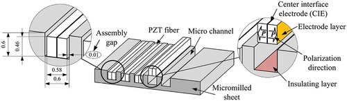
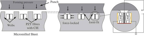
After micro assembly of the PZT fibers into the aluminum sheet, the forming process is used to close the assembly gap and clamp the PZT fibers. Therefore, a flat die is pressed on the top of the webs, which induces stresses, causing a material flow. Now the fibers are clamped in force-lock and form-fit. The process is illustrated in . The surfaces of the PZT fibers with contact to the channel walls are metallized. Furthermore, the fibers have a center interface electrode (CIE). The CIE is necessary for the realization of the electrical connection and polarization for the d33 effect according to on the right side. In order to avoid an electrical short circuit between the PZT fibers and the aluminum sheet, the bottoms of the channels are coated with an insulating layer.
Figure 2. Principle for the structural integration with joining by forming and the use of the piezoelectric d33-effect.
Numerical study on the geometrical process sensitivity
Deviations from the nominal dimensions of the joining partners (see occur as a result of the manufacturing. Inconvenient combinations of scattering of fiber dimensions and the micro channel dimensions lead to fiber overload or result in insufficient mechanical coupling. In order to investigate the effects of the deviations, the real dimensions of fabricated test samples are used to evaluate the influence of geometric scattering by a numerical simulation.
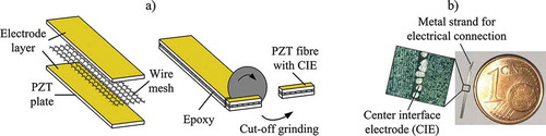
First the PZT-fiber arrays are fabricated. Therefore, two PZT plates with a thickness of 0.26 mm from the company Johnson Matthey Piezo Products (type M1100) are bonded together with an epoxy resin adhesive (J-B Weld) and with a wire mesh between them. Both surfaces of the plates are metallized with an electrode layer and then polarized. A schematic structure of the compound is represented in . The electrode layers and the wire mesh ensure the electrical connection. The thickness of the CIE is about 60 µm. The bonded plates are separated in equally sized fibers by precision cut-off grinding, which is also illustrated in (a). As mentioned above, the micro channels in the aluminum sheets are generated by a micro-milling process. The dimensions of all produced samples are measured using a digital microscope (Keyence VHX-600) for the numerical study on geometrical process sensitivity. gives the mean values with scattering range.
Table 1. Mean values and scattering range of the fiber dimensions and the channel dimensions.
Figure 3. a) Manufacturing process of PZT fibers with CIE, b) Finished produced test sample.
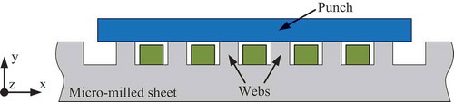
LS-Dyna Implicit with release SMP R9.1.0 (double precision) is used as solver. The forming load is applied with a control of the displacement until a maximum value. In a final step the geometry is unloaded to investigate the remaining clamping stresses in the fibers. Maximum and final stresses are monitored in the middle of each fiber (). The geometric scattering is determined by the optical scan of fibers as well as micro channels geometry before joining. In the model the mean value for channels width is shifted to 0.609 mm to avoid an overlapping of fiber and channel. The center interface electrode, described above, is not considered in the geometry model. In a first step only the influence of the dimensions of fibers and channels is included. The scattering of CIE thickness as well as irreversible deformation of CIE during joining is not part of this numerical study.
Figure 4. Geometry model for the sensitivity study.
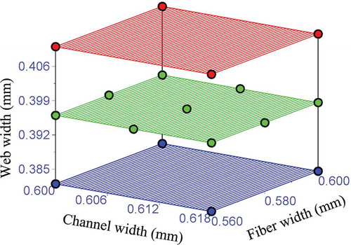
With a parameterized model an automatic geometry generation is realized to investigate the sensitivity of the chosen parameters channel width, fiber width and web width. Channel height and fiber height are excluded in this study because of the reproducible results of the micro-milling process for the channels. The parameter space is covered with a reference state and two additional simulations with parameter sets for upper and lower scattering limit. For the web width only the extremal values are considered. Hence, a total amount of 17 simulations are computed (). Especially the outer parameter-space border where fiber width equals channel width is only of theoretical interest. Due to the fitting difficulties during micro assembly, the fiber width has to be smaller than the channel width. The default mesh size for the rectangular axisymmetric elements was chosen to 20 µm according to a preliminary mesh size study. The fiber width is covered with 24 elements. Elements with shorter edge length of 10 µm lead to an overestimation of stresses especially at the singularities of the cavity bottom where 3 elements form a 270-degree corner. An element edge length of 30 µm covers the fiber width with 16 elements. The results are still comparable with the 20 µm-element solution.
Figure 5. Distribution of the geometric parameters in parameter-space.
For the isotropic hardening aluminum material model a true stress/true strain curve is determined in compression tests with cylindrical specimens. The curve is used with keyword *MAT_PIECEWISE_LINEAR_PLASTICITY and hence strain is strictly associated with the corresponding stress. The damage option as well as the strain rate dependency was deactivated in the material model. The parameters for the anisotropic elastic material model of the piezoceramic material are taken from [Citation11]. The *MAT_ORTHOTROPIC_ELASTIC material model was used. The brittle piezoceramic fibers break under low tensile stresses of about 30 MPa. But on the other hand, the manufacturer specifies maximum pressure stresses of about 600 MPa. The fibers are loaded with a maximum pressure of about 120 MPa in the simulation. Thus, the use of an elastic material model is sufficient.
In each calculation the stresses in the middle of all fibers are monitored. In the following only the third principle stress in the middle of the center fiber is discussed. The stress is always less than zero due to clamping of the fiber (the channel walls act as punch) and its orientation is always perpendicular to the side walls. Two points of the stress curves over process time are evaluated. First point: the stress minimum occurs when the maximum pressure is applied by the side walls. Second point: the residual stress in the fiber after joining and unloading gives the remaining pressure that clamps the fiber. In the study the absolute value of the third principle stress is used to account for the pressure load nature of the resulting stress component.
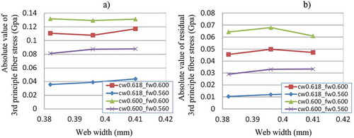
(a) shows the stress maxima reached in the process dependent on the geometric parameters channel width and fiber width. (b) gives the according residual stresses after unloading. The occurring clamping forces rise with lower gaps between fiber and channel. This is also valid for the residual stresses. While this correlation conforms to the expectations, the stress ranges (fiber pressure between channel walls) are unexpected high. A gap reduction from nearly 60 µm to zero results in a stress increase of 200%. The pressure of the channel walls is significantly dependent on the channel width and the fiber width. shows the same relation between fiber pressure and web width. There exists no dependency neither for the stresses at pressure maximum ((a)) nor for the residual stresses ((b)).
Figure 6. Distribution of absolute value of 3rd principle fiber stress dependent on channel width and fiber width, a) At pressure maxima, b) Residual stresses after unloading.
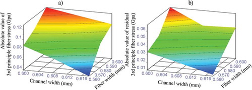
Figure 7. Absolute values of 3rd principle fiber stress in GPa dependent on web width, a) At pressure maxima, b) Residual stresses after unloading.
As a result, unfavorable combinations of channel width and fiber width may cause high clamping stresses in some fibers. This leads to higher final clamping situations on the one hand. On the other hand, it is possible that a critical fiber loading is reached, which has to be avoided to maintain the part functionality. Hence, a fiber status monitoring supports the process reliability. For this purpose the inherent sensor function of the piezoceramic material is used and described in the following sections.
Process monitoring with the aid of electrical impedance
The physical principle used for the monitoring of the PZT fibers during the joining is an analysis of the shifting and damping of the resonance modes in dependency of mechanical stress applied. Due to the fact that the PZT fibers are clamped in the longitudinal direction (see the first thickness resonance mode of the fibers in the d33-direction is influenced during the joining operation. The influence leads to a resonance mode change in the mechanical domain on the one hand and to a corresponding resonance mode change in the electrical impedance spectrum on the other hand. Hence, this dependency can be utilized as indicator of electrical impedance for the evaluation of the clamping-condition between the piezoceramic and the surrounding aluminum microstructure.
The electrical impedance of a single fiber in the vicinity of a resonance mode can be approximated by the equivalent VanDyke circuit model with lumped parameters [Citation12]. As illustrated in , the electrical behavior of the entire PZT-fiber array can be described by a parallelization of single fiber models. The index i enumerates the fibers. The capacitance C1,i represents the true electrical capacity and R1,i the true electrical contact resistance between the PZT fiber and the aluminum sheet. The parallel RLC-branch embodies the mechanical impedance of the first mechanical resonance mode of the fiber. The resistance R2,i, the capacitance C2,i and the inductance L2,i are equivalent to the mechanical damping, mechanical stiffness and inertial mass.
Figure 8. a) Electrical connection of piezo-metal modules, b) Equivalent electrical circuit of parallel PZT fibers in the vicinity of the first resonance mode, c) Simulated shift of impedance spectrum of PZT-fiber array in dependency of mechanic coupling where α* is the normalized coupling factor.
In [Citation13] proportionalities between the lumped parameters of the parallel RLC-branch and mechanical coupling factor αi are presented:
Thereby the coupling factor αi indicates the effectiveness of the piezoelectric conversion between the electrical energy Wel,i and the mechanical energy Wmech,i of the fiber. In [Citation14] the authors showed that the coupling factor αi can be changed by axial forces which cause destabilization or stiffening of a piezoceramic sample. The complex impedance Zi of a fiber i can be calculated as a function of the frequency f and the coupling factor αi by using the aforementioned proportionalities with the lumped parameters from Equation 1:
The over-all impedance of the transducer can be described by a parallelization of the single fiber models as shown in . By assuming identical electrical parameters for the fibers, the impedance of a transducer with n = 5 PZT fibers can be described with Equation 3:
Based on this analysis the impedance behavior of a PZT-fiber array is investigated in a simulative study. For this purpose, the coupling factor α*i is normalized to the load-free state of the fibers and stepwise varied between 60% and 100%. The lumped parameters of the simulated equivalent circuit where estimated at load-free conditions in the d33-direction of a single fiber from characteristic points of the impedance spectrum based on the experimental method introduced by DeAngelis and Schulze [Citation14,Citation15]. The simulation yields an impedance change driven by the electrical coupling factor as depicted in and demonstrates the feasibility of mechanical load monitoring by impedance spectroscopy.
Experimental
For the experimental investigation wires are attached to each CIE of a fiber and interconnected together to a PZT-fiber array. The bottom sides of the channels are coated with an insulating layer and a wire is connected to the aluminum sheet. Finally, the prepared PZT-fiber arrays are assembled in microstructured aluminum sheets (see ) and subsequently placed in the joining tool, as shown in . All experiments are done with the d33-effect of the PZT fibers. The interconnected wires of an array are electrically connected to a vector network analyzer (OmicronLab Bode 100). The flat upper joining tool is insulated with polyamide tape (Kapton KL-KAPT) to prevent short-circuiting of the CIE against the aluminum sheet and ground potential of the machine equipment. Experiments are performed on a material testing machine (Hegewald & Peschke Inspekt 150 kN). During the joining operation the upper tool moves downwards and applies stepwise a rising pressing force FPress to the webs of the microstructure. Hence, the fibers are continuously clamped through narrowing the channels as illustrated in .
Figure 9. a) Five unconnected PZT fibers assembled in the micro channels of an aluminum sheet, b) joining tool in open and closed position.

In order to locate the expected frequency range for the resonance mode, the series resonant frequency fs for the longitudinal mode is calculated according to Equation 4:
Using the frequency constant N3 of 1870 m/s (manufacturer data) and the active length l in the d33-direction of 0.52 mm, a series resonant frequency fs of 3.6 MHz of the thickness resonance mode is obtained.
Whilst the joining operation the impedance spectra of the interconnected fibers are measured at different levels of the increasing pressing force FPress and after the joining with lifted upper joining tool. During the rising of the pressing force FPress a decreasing of the impedance spectra over the measured frequency range, an increased damping and a frequency shifting of resonance-modes are observed. The resonance mode around 3.5 MHz shows a good sensitivity of the frequency shift and damping to the applied pressing force FPress. The value is close to the calculated frequency for fs. Based on this observation, the resonance mode can be utilized as monitoring indicator for the joining process. A series of joining with eight specimens reveals that a good clamping of the fibers is achieved when the resonance peak at around 3.5 MHz disappears. and exemplary show impedance spectra of two different transducers during the joining by forming operation at different pressing forces FPress.
Figure 10. Measured impedance spectra of PZT-fiber arrays during joining by forming at different pressing forces FPress up to 8 kN and after joining.
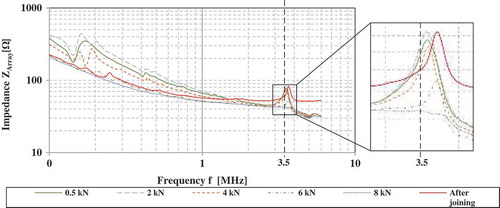
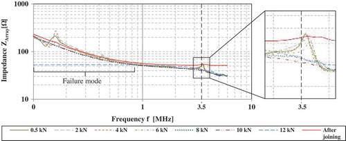
Figure 11. Measured impedance spectra of PZT-fiber arrays during joining by forming at different pressing forces FPress and after joining with failure mode due to excessive pressing forces up to 12 kN.
In the first case a good joining result is obtained by applying a maximum pressing force of 8 kN. The decreasing of the resonance peak (see during the joining indicates a good clamping of the fibers with the aluminum microstructure. The resonance peak at around 3.5 MHz shifts from 3.47 MHz at 500 N pressing force FPress to 3.55 MHz at 8 kN. At 8 kN the resonance peak disappears. A microscopic inspection (see ) after the joining shows a completely closed assembly gap and good fit between the fibers and the webs of the microstructure. Even no visible fiber-cracks or damages are found. Only the form-fit has not yet been fully achieved as the sectional view in shows. To this end, the process parameters must be adjusted, whereby the load limits of the fibers have to be considered.
Figure 12. Microscopic inspection results after joining, a) Joining result with forming up to 8 kN and no visible cracks, b) Failure mode due to excessive pressing forces up to 12 kN.
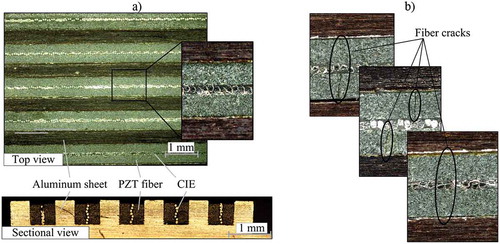
In the second case the pressing force is increased up to 12 kN. Up to 8 kN, the impedance behavior is similar to the previous example. The resonance peak at around 3.5 MHz shifts from 3.53 MHz at 500 N pressing force FPress to 3.62 MHz at 8 kN. At 8 kN the resonance-peak disappears again. Beyond 10 kN a drastic drop-down of the impedance is observed in the range of 0.1 MHz and 0.8 MHz. This indicates a damaging of the insulation film of the CIE. After joining, a microscopic inspection shows a number of visible fiber cracks in the range of the channels as illustrated in . Nevertheless, the proposed impedance analysis proves its feasibility for failure mode detection during the joining process in this case.
Furthermore, a significant decrease of the resonance peak beginning in the range of 4 kN is observed in the experiments, and thus represents the beginning of the actual clamping process. In addition, the clamping of the fibers after optical inspection appeared to be functionally sufficient for all fibers. However, to judge if only single fibers within the array fail because of high pressure, further investigation is needed.
After joining, a microscopic inspection shows a number of visible fiber cracks in the range of the channels as illustrated in . Nevertheless, the proposed impedance analysis proves its feasibility for failure mode detection during the joining process in this case.
Summary and conclusion
A procedure for the structural integration of PZT-fiber arrays with the technique joining by forming was presented. The effects of dimensional deviations for the joining process were shown by a numerical study of the geometric process sensitivity. Already differing tolerances with a span of 60 μm result in a 200% increase in pressure with the same joining force. These results demonstrated clearly the necessity of a monitoring method to ensure the functional reliability of the PZT-fiber array transducers during the joining process as well as the adjustment of a reproducible preload.
For this purpose, PZT-fiber arrays and microstructured aluminum were prepared as test samples. Electrical impedance spectra are recorded during the joining process via inherent sensor characteristics of the piezoceramic and finally evaluated. The impedance spectra of the interconnected fibers show a shift of the resonance point into higher frequencies as well as an attenuation of the signal. These findings enable the development of a novel monitoring method for the adjustment of a defined preload and avoiding an overload. Further work is intended to secure statistically the results of the monitoring method and the detection of the failure of single fibers in the array. Furthermore, the behavior of the electrical impedance spectrum under varying technological parameters of the joining process (i.e. different forming speeds and holding times) is a point in further studies. Additional, efforts are being done to minimize the manufacturing tolerances of the joining partners.
Acknowledgments
This research is supported by the Deutsche Forschungsgemeinschaft (DFG) in context of the Collaborative Research Centre/Transregio 39 PT-PIESA, subprojects A02, A03 and B01.
Disclosure statement
No potential conflict of interest was reported by the authors.
Additional information
Funding
References
- A. Schubert, V. Wittstock, H.-J. Koriath, S.F. Jahn, B. Müller, and M. Müller, Smart metal sheets by direct functional integration of piezoceramic fibers in microformed structures, Microsyst. Technol. 20 (2013), pp. 1131–1140.
- E. Glushkov, N. Glushkova, R. Lammering, A. Eremin, and M.N. Neumann, Lamb wave excitation and propagation in elastic plates with surface obstacles: Proper choice of central frequencies, Smart Mater. Struct. 20 (2011), pp. 1–11. doi:10.1088/0964-1726/20/1/015020
- K. Naveet and B. Suresh, Feasibility of energy harvesting from thin piezo patches via axial strain (d31) actuation mode, J. Civil Struct. Health Monit. 4 (2014), pp. 1–15.
- A. Koszewnik The optimal vibration control of the plate structure by using piezo-actuators. 17th International Carpathian Control Conference (ICCC), Tatranska Lomnica, Slovakia, (2016). 358–363.
- A. Schubert, V. Wittstock, S.F. Jahn, B. Müller, and M. Müller, Joining by forming of piezoceramic macro-fiber arrays within micro-structured surfaces of aluminum sheets, Production Eng. Res. Dev. 8 (2014), pp. 195–205. doi:10.1007/s11740-013-0498-7
- Y.Y. Lim and C.K. Soh, Damage detection and characterization using EMI technique under varying axial load, Smart Struct. Syst. 11 (2013), pp. 349–364. doi:10.12989/sss.2013.11.4.349
- A.N. Zagrai and V. Giurgiutiu, Electro-mechanical impedance, method for crack detection in thin plates, J. Intell. Mater. Syst. Struct. 12 (2001), pp. 709–718. doi:10.1177/104538901320560355
- F.G. Baptista, D.E. Budoya, V.A.D. de Almeida, and J.A.C. Ulson, An experimental study on the effect of temperature on piezoelectric sensors for impedance-based structural health monitoring, Sensors. 14 (2014), pp. 1208–1227. doi:10.3390/s140101208
- K.-Y. Koo, S. Park, -J.-J. Lee, and C.-B. Yun, Automated Impedance-based structural health monitoring incorporating effective frequency shift for compensating temperature effects, J. Intell. Mater. Syst. Struct. 20 (2009), pp. 367–377. doi:10.1177/1045389X08088664
- W.-G. Drossel, V. Wittstock, S. Hensel, and M. Schmidt, Condition monitoring of piezoceramic fibers during joining by forming, Procedia Technol. 26 (2016), pp. 144–151. doi:10.1016/j.protcy.2016.08.020
- S. Hosseini-Hashemi, M. Es’haghi, and H. Rokni Damavandi Taher, An exact analytical solution for freely vibrating piezoelectric coupled circular/annular thick plates using Reddy plate theory, Compos. Struct. 92 (6) (2010), pp. 1333–1351. doi:10.1016/j.compstruct.2009.11.006
- IEEE Standard on piezoelectricity IEEE/ANSI Std. 176., The Institute of Electrical and Electronics Engineers, Inc New York, USA (1987).
- H.A.C. Tilmans, Equivalent circuit representation of electromechanical transducers: II. Distributed parameter systems, J. Micromech. Microeng 7 (1998), pp. 285–309. doi:10.1088/0960-1317/7/4/005
- G. Lesieutre and C. Davis, Can a coupling coefficient of a piezoelectric device be higher than those of its active material? J. Intell. Mater. Syst. Struct. 8 (10) (1997), pp. 859–867. doi:10.1177/1045389X9700801005
- D.A. DeAngelis and G.W. Schulze Optimizing piezoelectric crystal preload in ultrasonic transducers. 38th Annual Symposium of the Ultrasonic Industry Association (UIA), Canada (2009).