
 ?Mathematical formulae have been encoded as MathML and are displayed in this HTML version using MathJax in order to improve their display. Uncheck the box to turn MathJax off. This feature requires Javascript. Click on a formula to zoom.
ABSTRACT
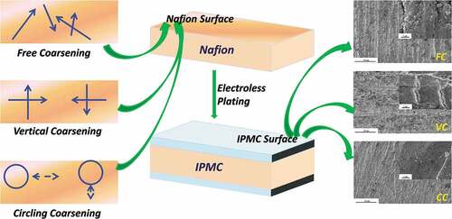
In this paper, three different roughening route planning methods (free coarsening, vertical coarsening, circling coarsening) were designed to pre-treat the basement membrane. The platinum IPMC was prepared by electroless plating to observe their surface morphology and test their performances such as output displacement and blocking force. The results show that the platinum electrode of the vertical coarsening route planning of IPMC is distributed in the shape of fish scales and is the most compact and regular on the surface electrode. The thickness of the platinum electrode layer is about 13 μm, the maximum output displacement is 54.89 mm, the blocking force of 15.46 mN, and the maximum strain energy density of the IPMC of 2.44 KJ/m3. Vertical coarsening route planning can significantly improve the electrodynamic properties of IPMC, and it is recommended that the surface roughening of IPMC be utilized in the research and application of IPMC. It lays a certain experimental foundation for the performance improvement and innovation research and development of IPMC in the subsequent stage.
Graphical Abstract
1. Introduction
With the rapid development of science and technology, the demand for intelligent and miniaturized materials is increasing gradually, the performance of intelligent materials has a higher requirement. Since the introduction of smart materials in the 1980s, to the present fourth generation of materials, smart materials have gradually become the development object of key cutting-edge new materials technology [Citation1]. Ionic polymer-metal composite (IPMC), as one of the new smart polymer materials, with the characteristics of low voltage and large deformation, has been widely concerned [Citation2,Citation3], and have been applied in artificial muscles, bionic robots, aerospace equipment, bioengineering, flexible mechanical brakes, medical instruments, and other fields [Citation4–Citation6]. It is composed of electrode material on both sides and basement membrane wrapped in the middle. The anions in the basement membrane are fixed on the main chain of the polymer, and the cations can migrate under the stimulation of voltage, which leads to the generation of the osmotic force and electrostatic force, and eventually causes the IPMC to bend toward the anode [Citation7,Citation8].
During the preparation of IPMC, the surface roughening of the basement membrane has a critical influence on its properties [Citation9–Citation11]. Stoimenov BL et al. [Citation12] compared the isotropic and anisotropic sandpaper coarsening methods, and the results showed that the bending response of anisotropic grinding was 2.1 times that of isotropy. Choi NJ et al. [Citation13] used three methods of anisotropic plasma etching, isotropic plasma etching, and sandblasting to do experiments, and found that anisotropic plasma etching has far more performance than the other two methods, and its response speed is 2 times that of sandblasting treatment, and the output displacement is 1.5 times. Kim SJ et al. [Citation14,Citation15] and Kim JH et al. [Citation16] also used the method of plasma etching to make the surface show a needlelike micropore structure, the membranes undergo morphological, as well as surface chemical structural changes during the process of plasma treatments. It was found that the change in the surface morphology of the electrode could improve the corresponding working time, output force, electrodynamic displacement of IPMC. Lee SH et al. [Citation17] and Tak Y et al. [Citation18] have significantly improved the electrodynamic bending performance of IPMC after surface coarsening treatment. In order to get more grooves on the base film surface and more surface texture, He QS et al. [Citation19] used the method of adding abrasive to grind, which combined with the hot pressing of mold, the performance of IPMC has been significantly improved. Surface roughening device included friction head, membrane jig, and fixed stage was demonstrated for the IPMC membranes based on linear reciprocating motion of the UMT-2 friction-abrasion testing machine [Citation20]. Microneedle roller roughening was proposed as an effective roughening method for an IPMC, roughening the membrane after the initial impregnation process to form a deep needlelike penetrated electrode, and subsequently obtained an IPMC with large deformation at both low and high frequencies [Citation21]. Although the above methods improve the actuation performance of IPMC to a certain extent, these coarsening methods are not ideal, for example, it is difficult to control the ejection speed of sandblasting treatment, which will cause irreparable physical damage to the base membrane; the chemical coarsening will produce erosion effect and corrode the structure of the basement membrane; the mechanical coarsening needs to consider the grinding head material, rotating frequency, applying pressure and other variables, so it is difficult to achieve stable grinding; the plasma surface treatment destroys the basement membrane structure, which is not conducive to improving the performance. At the present stage, there is not any uniform and standardized surface-coarsening method to define the grinding method of the basement membrane. Therefore, this paper attempts to explore a convenient and simple grinding method for experimental research. On the basis of traditional sandpaper grinding, three different coarsening route plannings are designed for free coarsening (FC), vertical coarsening (VC), circling coarsening (CC) respectively. After coarsening the basement membrane, the platinum-based IPMC is prepared by the same electroless plating process. The surface and cross-section morphology of the IPMC with three coarsening methods were observed by scanning electron microscope (SEM), and the output displacement, the output force of the IPMC were compared and analyzed to provide the data reference for the later preparation process of IPMC, which laid a theoretical foundation for improving the actuation performance of IPMC.
2. Experimental
2.1. Materials
The Nafion-117 membrane was produced by Dupont company with a thickness of 183 um. Platinum ammonia compound (98%) was purchased from Shanghai Civic Chemical Technology Co., Ltd. The hydrazine hydrate (80%) was obtained from Tianjin Fuyu Chemical Co., Ltd. And the sodium borohydride (98%) was from the Tianjin Fuchen chemical factory. Hydroxylamine hydrochloride (98.5%), lithium chloride (95.0%), and lithium hydroxide (97.0%) were purchased from Guangdong Guanghua technology Co., Ltd. The ammonium hydroxide (25.0%) was from Zhengzhou Paini chemical factory.
2.2. Fabrication
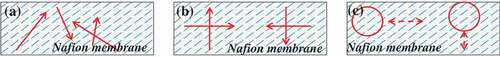
In this experiment, Nafion-117 membrane was selected as the basement membrane and cut into a size of 50 mm × 10 mm specimen. The three coarsening route planning approaches designed are as follows: free coarsening (FC), vertical coarsening (VC), and circling coarsening (CC), as shown in . Before coarsening, the basement membrane is hereby fixed on the loading table to keep it level and then treated according to different coarsening methods. FC: the basement membrane is used random grinding without a specified track, selected 800 mesh, 1000 mesh sandpapers to operate repeatedly for 6 min, respectively, the front and back surfaces are opaque. VC: first can be polished in any direction, the second grinding direction is perpendicular to the previous, then the same way with FC, using different sandpapers to operate repeatedly the membrane for 12 min, so that the front and rear sides are uniformly opaque. CC: using multi-function grinding machine to fix the grinding head to drive sandpaper to rotate, repeatedly grinding to roughen the basement membrane. Notably, the three approaches adopted 800 mesh and 1000 mesh sandpapers for coarsening for 6 min respectively, a total of 12 min.
Figure 1. Schematic diagram of different coarsening route planning (a) FC (b) VC (c) CC.
The coarsened basement membrane was ultrasonically cleaned to remove the surface residual attachment, subsequently placed in a hydrochloric acid solution of 2 mol/L to remove surface impurities and other ions within its membrane. The membrane was placed in 2 mg/mL of platinum ammonia complex solution and adsorbed for 14 h under ambient temperature. The magnetic heating agitator was set at 45°C, 55°C, 60°C, respectively, and 3 mL of NaBH4 was added every 10 min at each temperature for a total of 15 times. Rinsed with deionized water and placed in 0.1 mol/L of hydrochloric acid for about 30 min to remove platinum particles not completely deposited.
The 45.72 mg dichlorotetracycline and 3 mL 8% NH3∙H2O solution was added to deionized water. The membrane was added to the solution and placed on a 45°C magnetic heating agitator with 4 mL of 1% hydroxylamine hydrochloride solution and 2 mL of 25% hydrazine hydrate solution. Add 3 mL 1% hydroxylamine hydrochloride solution and 2 mL 25% hydrazine hydrate solution after 20 min, add 3 mL 1% hydroxylamine hydrochloride solution and 2 mL 25% hydrazine hydrate solution after 10 min. Repeat the above steps 4 times and then heat in a high-temperature water bath with 0.1 mol/L hydrochloric acid for 30 min to remove the residual NH4+. 1 g of LiCl and 40 mg of LiOH were configured into 60 mL solution, and then the IPMC under different coarsening modes was placed in turn for ion exchange. After full exchange for 12 h, the IPMC was removed and put into deionized water for storage.
2.3. Measurements
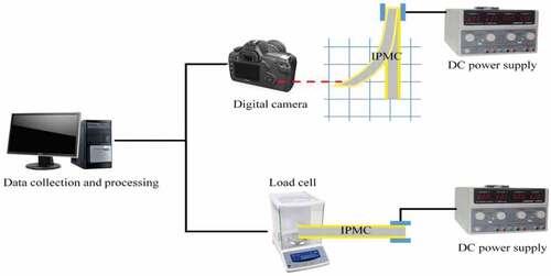
The scanning electron microscope (JSM-6390A, JEOL, Japan) was used to observe the surface morphology of the IPMC (the distribution uniformity of the electrode and the state of metal particles) and the cross-section morphology (the degree of penetration of the electrode layer and the degree of bonding of the interface). The test platform of driving performance for IPMC is shown in , which is mainly composed of a DC power supply (LPS605D, LODESTAR, China), a load cell (FA2004, Shanghai precision instrument co., LTD., China), a digital camera (a frame grabber, China), and data collection and processing module. The sample size of IPMC is 50 mm × 10 mm, the clamping part for 10 mm, and the test point for the end of IPMC. The balance was used to measure the mass of the specimen with a precision of 0.0001 g, and which could be converted into the force of IPMCs. The displacement of IPMCs was recorded with a camera under a voltage stimulus of 3–7 V. All measurements were performed at room temperature, taking the average of three measurements.
Figure 2. Schematic diagram of the testing platform of displacement and force of IPMCs.
3. Results and discussion
3.1 Macrophotograph
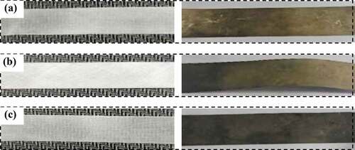
Comparing the substrate treated with FC, VC, CC, and the corresponding IPMC (), it can be found that after three kinds of coarsening, the macroscopic morphology of the basement membrane is basically the same, all of which show as impermeable. Compared with the other two coarsening methods, the VC has the largest degree of roughness. At the same time, it can be seen that the IPMC surface of FC has partial inhomogeneity, probably because the site is not conducive to the growth of platinum particles in the electroless plating process, or adhesion of platinum particles is low under the process of FC. And the other two surfaces are relatively uniform. While we found that the surface of the prepared IPMC samples showed dark gray, mainly because we carried out four electroless platings in the process of preparing the IPMC, ensured the quality of the coating, and the layer of platinum particles was denser, which was also confirmed by subsequent SEM tests.
Figure 3. Comparison of macroscopic photographs before and after electroless plating with different roughing methods (a) FC (b) VC (c) CC.
3.2 SEM
is SEM of the surface electrode of IPMCs. It can be intuitively seen that the distribution of platinum particles after FC is relatively dense, the distribution trace of the river, and there is basically no local accumulation (preferential growth of deposition) of platinum particles. From the magnified figure in the upper right corner of ), it can be seen that the distribution of platinum particles on the electrode surface shows a sheet-like and irregular. The distribution of platinum particles is significantly dense after VC from ), the platinum metal particles are stacked, which presents a more complex mesh structure, and some folds here, which makes the distribution of electrode layer more dense. The local amplification presents regular fish scale sheet-like on the electrode surfaces with significantly more platinum particles than the other two coarsening modes. ) shows that the electrode distribution of CC is slightly inferior to that of VC, but stronger than that of FC. The distribution of platinum particles is extremely uniform, but the magnification shows tiny cracks on the electrodes. Although CC has some advantages in controlling the force, it is still easy to have local residual stress. Therefore, the complexity of VC is the largest, and the roughness of the basement membrane increases, and the electrode distribution on the surface of IPMC becomes more compact.
Figure 4. SEM of the surface electrode of IPMCs (a) FC-IPMC (b) VC-IPMC (c) CC-IPMC.
Figure 5. Cross-section morphology of IPMCs (a) FC-IPMC (b) VC-IPMC (c) CC-IPMC.
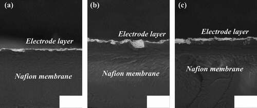
In order to observe the thickness distribution of the electrode and the combination of the interface under different coarsening modes, the cross-section morphology of the IPMC was analyzed as shown in . It can be obviously seen that a layer of surface electrode is formed on the surface of the membrane after electroless plating, that is, platinum metal electrode. The cross-section morphology of various IPMCs is not very obvious, this may be due to there is embrittlement of the specimens using liquid nitrogen before SEM observation to show neat fracture morphology. Carefully contrast, the thickness of the electrode layer of FC-IPMC is about 4.5 μm in ), and its electrode layer is more regular and symmetrical. The thickness of the electrode layer of the VC-IPMC is 3–13 μm in ), the distribution of electrode layer is not symmetrical. The maximum thickness of electrode layer is about 13 μm and the minimum thickness of 3 μm. This is mainly due to the uneven distribution of the platinum particles deposited in the electroless plating, which increases the contact area between the membrane surface and the electrode, and expands the interfacial area between the membrane and the electrode, and improves the ability of the platinum particles to be deposited and adsorbed. The thickness of the electrode layer of the CC-IPMC in ) is between 2 μm and 9 μm, and its electrode distribution is also irregular.
3.3 Deformation displacement
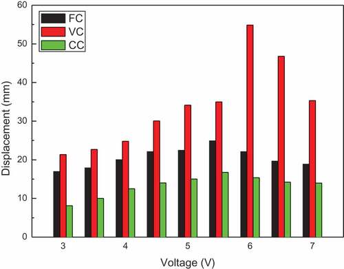
shows the maximum deformation displacement of the IPMC under different coarsening modes varies with the voltage. As the voltage increases, the displacement increases first and then decreases. The displacement of the VC IPMC reached a maximum of 54.89 mm at a voltage of 6 V, whereas the largest displacement points of the other two IPMCs are 5.5 V. Moreover, it is found that the changes of FC and CC are very slowly under the stimulation of voltage, while VC changes very quickly in the range of 5.5–6 V, which can quickly affect the actuation performance of IPMC. Furthermore, it is shown that different coarsening methods have a great influence on the performance of IPMC. The displacement of CC is relatively small, which may be caused by the inaccurate setting of grinding parameters, resulting in the lack of surface roughness and adhesion, therefore. The VC of the surface can significantly enhance the electrodynamic output displacement of the IPMC. The VC method makes the surface of Nafion membrane to be addressed in both vertical and horizontal directions, promoting surface roughness. During electroless plating, these rough sites provide favorable positions for nucleation of platinum particles. And the deposited sites continue to grow with the increase of the number of electroless plating, the thickness of the platinum electrode layer is further increased, and the state of the electrode layer directly affects the performance of IPMC. The displacement of FC is located between VC and FC, so it is not conducive to enhance the actuation performance of IPMC.
Figure 6. Displacement of IPMCs.
3.4 Blocking force
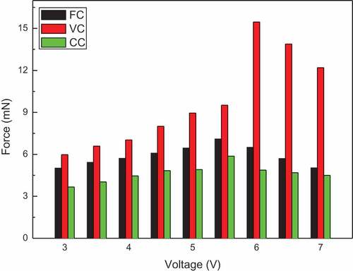
The blocking force of the IPMC with different coarsening methods varies with the voltage, as shown in . The blocking force of IPMCs is the same as the displacement. The forces of FC and CC IPMCs reach the maximum at 5.5 V, and then the force of VC increases rapidly to the maximum when the voltage increases to 6 V, 15.46 mN, which is obviously higher than that of the other two coarsening modes, and the force of the other two coarsening methods is reduced to a certain extent. The blocking force of VC-IPMC has the same advantage as the displacement, the method of VC promotes the roughness of the membrane, and provides favorable nucleation and growth for platinum particles. The force of FC has been lower than that of VC, and there is no considerable fluctuation. The force of CC is relatively weak in the overall view. It can be observed that in the process of preparing IPMC in the laboratory, the surface of IPMC can be roughened by using the VC route planning methods to obtain higher performance.
Figure 7. The blocking force of IPMCs.
3.5 Strain energy density
In order to better reflect the influence of different coarsening modes, this paper comprehensively evaluates the electrodynamic properties of IPMC through Strain energy density. In the process of bending deformation, IPMC can be approximated as a cantilever beam, while ignoring the effect of shear strain energy. The strain energy is calculated using the following equation [Citation22]
where and
represent the bending moment and the moment of inertia, respectively.
is electric field intensity,
is the length of IPMC.
According to Euler–Bernoulli beam theory,
where ,
and
represent the blocking force, displacement, and curvature radius of IPMC at time t, respectively.
The strain energy density can be expressed as
where and
are the width and thickness of the IPMC, respectively.
Assuming that the displacement and force of IPMC reach the ideal state at the same time. According to EquationEquation (5)(5)
(5) , the strain energy densities of various IPMCs at 5.5 V are calculated, as shown in , it can be seen that the VC of strain energy density is significantly higher than that of FC and CC. It also further indicates that VC can improve the strain energy density of IPMC, thus increase the comprehensive electrodynamic properties of IPMC.
Table 1. Maximum strain energy density of the IPMCs (Unit: KJ/m3).
4. Conclusion
IPMC has the advantages of low power consumption, large bending deformation under low voltage, light weight, and good flexibility, in addition to being an actuator, it has been studied as a sensor and super-capacitor with a transducer reverse effect. Thus, they can offer great potential for many applications including robotics, aerospace, and energy storage. In this paper, based on the surface-coarsening process of IPMCs, we designed three surface coarsening route plannings, i.e., FC, VC, CC, with the intention to develop a roughening method suitable for experimental research, standard unified, simple, and efficient grinding method. The micromorphology and performance of IPMCs designed by three different coarsening methods are measured and compared. The results show that the distribution of the surface electrode of VC-IPMC is scale-like and the most compact and regular, and the maximum thickness of the electrode layer is about 13 μm. And the maximum displacement is 54.89 mm, the force of 15.46 mN, the Maximum strain energy density of 2.44 KJm/m3. VC route planning is beneficial to improve the integrated electrodynamic properties of IPMCs. Considering the production and processing cost of IPMC, VC has achieved excellent performance such as economy, environmental protection, green, and no pollution. The VC route planning method is recommended for surface roughening of IPMCs in the research and application of IPMCs.
Acknowledgments
The authors wish to express thanks to the support from the Key Science and Technology Program of Shaanxi Province of China.
Disclosure statement
No potential conflict of interest was reported by the authors.
Additional information
Funding
References
- MohdIsa W, Hunt A, HosseinNia H. Sensing and self-sensing actuation methods for ionic polymer-metal composite (IPMC): a review. Sensors. 2019;19(18):3967.
- Wu G, Hu Y, Zhao J, et al. Ordered and active nanochannel electrode design for high performance electrochemical actuator. Small. 2016;12(36):4986–4992.
- Li J, Ma W, Song L, et al. Superfast-response and ultrahigh power-density electromechanical actuators based on hierarchal carbon nanotube electrodes and chitosan. Nano Lett. 2011;11(11):4636.
- Yang L, Zhang D, Zhang X, et al. Fabrication and actuation of Cu-ionic polymer metal composite. Polymers. 2020;12(2):460.
- Wu G, Hu Y, Liu Y, et al. Graphitic carbon nitride nanosheet electrode-based high-performance ionic actuator. Nat Commun. 2015;6(1):7258.
- Yang L, Zhang D, Zhang X, et al. Prediction of the actuation property of cu ionic polymer–metal composites based on backpropagation neural networks. ACS Omega. 2020;5(8):4067–4074.
- Park JH, Lee SW, Song DS, et al. Highly enhanced force generation of ionic polymer−metal composite actuators via thickness manipulation. ACS Appl Mater Interfaces. 2015;7(30):16659–16667.
- Bian K, Liu H, Tai G, et al. Enhanced actuation response of Nafion-based ionic polymer metal composites by doping BaTiO3 nanoparticles. J Phys Chem C. 2016;120:12377−12384.
- Kim KJ, Shahinpoor M. Ionic polymer metal composites: II. Manufacturing techniques. Smart Mater Struct. 2003;12(1):65–79.
- Jeon J-H, Yeom S-W, Oh I-K. Fabrication and actuation of ionic polymer metal composites patterned by combining electroplating with electroless plating. Compos Part A Appl S. 2008;39(4):588–596.
- Jin N, Wang BF, Bian K, et al. Effect of surface roughening on the manufacture and performance of IPMC. J Funct Mater. 2008;39(11):1933–1936.
- Stoimenov BL, Rossiter JM, Mukai T. Anisotropic surface roughness enhances bending response of ionic polymer-metal composite (IPMC) artificial muscles. Proc SPIE. 2006;6413:641302.
- Choi N-J, Lee H-K, Jung S, et al. Electroactive polymer actuator with high response speed through anisotropic surface roughening by plasma etching. J Nanosci Nanotechnol. 2008;8(10):5385–5388.
- Saher S, Moon S, Kim SJ, et al. O2 plasma treatment for ionic polymer metal nano composite (IPMNC) actuator. Sensor Actuat B-Chem. 2010;147(1):170–179.
- Kim SJ, Lee IT, Kim YH. Performance enhancement of IPMC actuator by plasma surface treatment. Smart Mater Struct. 2007;16(1):N6–N11.
- Kim JH, Sohn J, Cho JH, et al. Surface modification of Nafion membranes using atmospheric-pressure low-temperature plasmas for electrochemical applications. Plasma Process Polym. 2008;5(4):377–385.
- Lee SH, Kim CJ, Hwang HW, et al. Performance enhancement of IPMC by anisotropic plasma etching process. Proc of SPIE. 2009;7287:7287221–7287228.
- Noh T-G, Tak Y, Nam J-D, et al. Electrochemical characterization of polymer actuator with large interfacial area. Electrochim Acta. 2002;47(13–14):2341–2346.
- He QS, Yu M, Zhang XQ, et al. Electromechanical performance of an ionic polymer–metal composite actuator with hierarchical surface texture. Smart Mater Struct. 2013;22(5):055001.
- Yang X, Yu M, Wang YD, et al. Effects of surface roughening method on performance of IPMC artificial muscle. Chinese Sci Bull. 2016;61(23):2620–2628.
- Chang LF, Yang Q, Niu QZ, et al. High-performance ionic polymer–metal composite actuators fabricated with microneedle roughening. Smart Mater Struct. 2019;28(1):015007.
- Zhao D, Li D, Wang Y, et al. Improved manufacturing technology for producing porous Nafion for high-performance ionic polymer–metal composite actuators. Smart Mater Struct. 2016;25(7):075043.