
ABSTRACT
Irradiation with swift heavy ions causes the deformation of Ferric nanoparticles in direction of the ion beam. Fe nanoparticles with mean diameter of about 20 nm were prepared by gas flow sputtering and subsequently confined within silica films. Two silica films wherein two different densities of Fe nanoparticles are encapsulated were irradiated with 50 MeV Ag ions with fluences of few 1014 ions.cm−2 at 300 K and normal incidence. Transmission electron microscopy analysis shows that the spherical Fe nanoparticles are deformed into prolate nanorods aligned in direction of the incident ion beam. The depth distribution profiles of irradiated particles reveal the presence of a critical fluence above which the elongation kinetics becomes dependent on the nanoparticles density. Analysis indicates that for the lower density particles, a saturation length is reached under irradiation to fluence between 3–4 × 10¹⁴ ions.cm−2. However, for the higher density, collective growth into aligned nanowires is presumed to take place. Hysteresis curves of the saturation magnetization and coercivity indicate an increasing magnetic anisotropy, which can be correlated with the deformation of nanoparticles in the direction of the ion beam.
Graphical Abstract
1. Introduction
Nano-scale particles (NPs) are currently receiving an increasing scientific interest because of their various fascinating optical [Citation1,Citation2], electrical [Citation3] and magnetic properties [Citation4–Citation6]. Strong scattering and absorption resonances of metallic NPs occur at optical frequencies that are determined by the shape morphology, size aspect ratio and dielectric environment of the particles [Citation7]. Such effect has been known and exploited for centuries by glassmakers particularly in stained glass windows and decorative glass artwork. Moreover, the chemical characteristics of NPs such as surface area, mechanical stability, and reactivity, make them suitable candidates for catalysis [Citation8] and sensing applications [Citation9]. The possibility to tune and customize the physical properties of various microscopic [Citation10,Citation11] and nanoscopic objects [Citation12,Citation13] by modulating the shape using energetic ion beam irradiations represents a unique approach that is independent of many of the constraints associated with conventional shape modification methods. While there has been a great deal of published articles on irradiation-induced shape modification, so far, the investigations are largely localized in particular noble metallic NPs such as Co [Citation14,Citation15], Au [Citation16–Citation26], Ag [Citation27–Citation30] and Ni [Citation31–Citation33]. The high sensitivity of such NPs to the energy deposited in their electronic systems makes them particularly attractive for shape modification by using ion beam irradiation. The impact of swift heavy ions (SHI) of some MeV/amu in a solid instantaneously generates a long, radial anisotropic region of highly excited material, denoted as the ion track. The heat transfer to the surrounding material leads the ion track to cool down, and the anisotropic strain resulting from the stress relaxation to freeze in. An established model [Citation34–Citation39] based on continuum mechanics taking into account the energy of the incident ions, material thermal and mechanical parameters, the NPs size effects, and NP-substrate interactions, has qualitatively described the observed shape deformation for non-crystalline objects such as colloidal silica glass [Citation40] and amorphous silicon films and pillars [Citation41]. The model has always predicted an oblate shape formation, i.e. contraction in the direction of the ion beam and a concomitant expansion perpendicular to it. Obviously, the ion-induced elongation of the metallic NPs, which are aligned parallel to the beam direction, does not follow this model and another mechanism must be at play. Presumably, the deformation of the metallic NPs is a result of the composite nature of the material, i.e. of processes that affect both the metal and the surrounding silica. Therefore, it had little, despite the many experiments, the irradiation-induced elongation mechanism of metallic NPs is not clearly understood, at least in great detail. The current work reports on the irradiation-induced shaping effects on unexplored ferromagnetic materials; i.e. Ferric (Fe) NPs. The motive of the current work is the fact that most of the NPs properties can be tuned by modification of the size and shape. However, our goal is not to explore the modified properties in detail, but rather an implementation of one different material parameter within the resulting elongation characteristics.
2. Experimental procedures
Fe NPs were prepared by using a gas flow sputtering (GFS) method [Citation42–Citation44]. Within the GFS process, a high negative voltage is applied to the target and thereupon acceleration of Ar ions, Fe atoms sputtered off the target surface. Ar flow with 99.999% purity was introduced in the sputter chamber through the target. When necessary, He gas flow was used. The sputtering chamber was evacuated to a base pressure of 4 × 10⁻⁴ Pa prior to the sputtering. Fe nanoclusters are sputtered from Fe targets (99.95%) of 2.5-inch diameter and 0.120-inch thickness, bonded onto a copper backing plate. NPs were formed by aggregation of clusters onto a Si-SiO2 substrates measuring 10 × 10 mm2 area. The thickness of the native SiO2 in the substrate amounts to 200 nm. The applied sputtering pressure at which Fe NPs were prepared was 150 Pa. The distance between the target and the exit aperture during sputtering; denoted as NP aggregation length, was about 200 mm. The discharge power was 290 W and the Ar flow rate was about 490 SCCM.
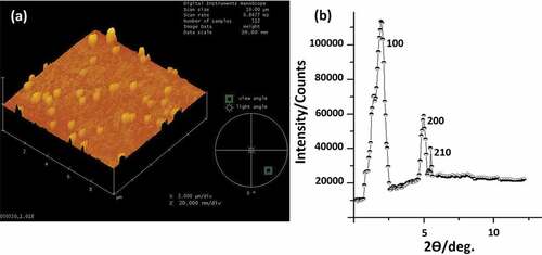
Fe NPs were prepared with two different densities amount to approximately (0.65x10⁹ ± 10%) and (1.5x10¹⁰ ± 10%) particles/cm2, respectively. Several physical and optical techniques have been used to examine the morphology, size, and shape of the Fe NPs. The average size of the NPs is examined by inspection of the height profile of the atomic force microscopy (AFM) measurements operated at tapping-mode; see ). The latter reveals the formation of an average size of Fe NPs ranging between 20–25 nm diameters. Besides, AFM indicates the uniformity of the particles spatial distribution. X-ray diffraction (X-RD) measurements are performed to characterize the structure of the grown Fe NPs. X-RD indicates the presence of α-Fe at crystalline nature with 100, 200 and 210 bcc structure, ).
Before irradiation, a secondary covering layer of SiO2 with a thickness of 200 nm was sputtered by reactive deposition on top of the Fe NPs and the underlying SiO2 film. Thus, the Fe NPs are confined in a single plane in a sandwich of 400 nm SiO2 matrix. The latter structure were subsequently annealed at 910°C in an open furnace for 15–20 minutes. The annealing step aims at providing excessive interdiffusion between the top and the bottom silica films, which could lead to an ultimate contact between the oxide and the Fe NPs. It is noteworthy to mention that the annealing of the α-Fe at temperature of 910°C for 15–20 minutes could facilitate the transformation into the γ-Fe [Citation38]. Since Fe has a strong affinity with oxygen, we expect the Fe NPs to be oxidized, at least within the outer shell of the NPs surface. In fact, the effect of oxidation on the magnetic properties of magnetite materials has been reported a number of times in literature [Citation45–Citation47]. A previous study by K. Simeonidis et al [Citation48]. showed that the X-ray diffraction spectra of 15 nm Fe NPs produced by thermal decomposition revealed instant oxidation of iron and the formation of wüstite and magnetite after exposure to air.
The density, layer thickness, and size of the Fe NPs in the silica films have been measured by using Rutherford backscattering spectrometry (RBS). RBS provides quantitative information about the composition of the Fe NPs layered structure by analyzing the energy distribution and the yield of the backscattered ions at a certain angle. RBS measurements were carried out at normal incidence geometry applying 4He+ ions with an energy of 2 MeV. The spectra recorded from the RBS analysis are collected simultaneously at two detectors at scattering angles of 120° and 170°, respectively. The data presented in the current study is collected from the 120° scattering angle detector, which has the best depth resolution. The results obtained from the 120° detector have been compared to those deduced from the 170° detector whenever necessary to warrant the internal consistency of the experimental data sets.
Figure 1. (a) (Color online) 3D Atomic force microscopy (AFM) image of Fe nanoparticles prepared by gas flow sputtering on a Si-SiO2 surface. The nanoparticles size is deduced from the height profile and found to amount to 20 nm diameter (±3 nm). (b) X-ray diffraction patterns of Fe nanoparticles prepared under sputtering pressure of 150 Pa, nanoparticle aggregation length of 200 mm, discharge power of 290 W, and Ar flow rate of about 490 SCCM. The XRD reveals that only α-Fe with bcc structure was detected. The transverse dimension of NPs appears artificially broadened due to the tip size convolution, which is typical characteristics of the AFM measurements.
High-resolution transmission electron microscopy (HR-XTEM) is used to inspect the presence of the Fe NPs in the silica films and further to characterize their size and shape before and after SHI irradiation. Samples were prepared in cross-sectional geometry applying an acceleration voltage of 200 kV. The samples were irradiated with 50 MeV Ag ion beam for fluences of few 1014 ions.cm−2 at RT and normal incidence geometry. The current stability during irradiation has been inspected by using a micrometer-sized Faraday cup. A massive metallic holder is used for mounting the samples for irradiation. A conductive paste is applied to avoid successive heating of the samples during the irradiation. Electrostatic sweeping of the beam has been made over the entire samples area of 10 × 10 mm2 to obtain a homogeneous irradiation. The projection range distribution of the applied silver ions in SiO2 was calculated by SRIM 2008 code [Citation49] and found of about 9.1 µm. The latter is much larger than the thickness of the SiO2-Fe NPs containing layer. Hence, the irradiation is only used for the deposition of energy into the SiO2–Fe NPs layer. The hysteresis curves of the saturation magnetization and coercive field (Ms and Hc) were inspected for investigation of the effects of the irradiation-induced elongation on the corresponding properties of the Fe NPs. Ms and Hc were measured at 2 K applying an external magnetic field in a direction perpendicular to the surface of films containing the Fe NPs.
3. Results and discussion
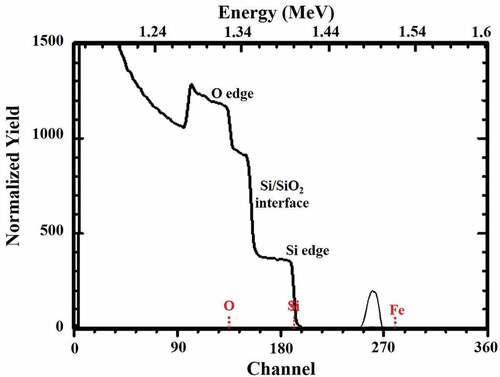
The integrity of the SiO2/Fe NPs layer structure before and after the irradiation has been assessed by an inspection of the RBS spectrum. shows the RBS spectrum of a SiO2-Fe NPs containing layer before irradiation with the SHI. By inspection of the layer structure, the O edge is found to occur at ~ 1.33 MeV. The Si (66%) from the Si/SiO2 interface occurs at ~ 1.35 MeV. The Si (100%) edge from the substrate occurs at an energy of ~ 1.40 MeV. A distinct peak at ~1.5 MeV is observed, which arose by scattering from Fe in the substrate. The occurrence of the distinct peak in the RBS spectrum confirms that Fe NPs are present in the silica film. While the distinct Fe RBS peak designates the depth distribution of the Fe species in the substrate, its full-width at half maxima (FWHM) provides indirect information about the NPs size. Therefore, an easier and faster approach to calculate the size of the Fe NPs has been followed by inspection of the FWHM of the Fe RBS peak before and after irradiation with the SHI. It is noteworthy to mention that the extraction of the exact size from the RBS analysis is difficult; i.e. only a qualitative trend can be followed. However, to warrant the consistency of our experimental data sets, the results obtained from RBS has always been verified by HR-XTEM.
Figure 2. RBS spectrum of a SiO2-Fe NPs layer structure. The oxygen channel, the Si/SiO2 interface and Si edge are indicated. The distinct peak belongs to Fe NPs in the SiO2 layer. The surface channel of the Fe is indicated.
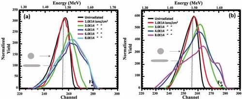
After irradiation, we examined the elongation of Fe NPs as a function of the NPs density and irradiation fluence. show the evolution of the Fe peak with fluence extracted from the RBS spectrum for the two silica films containing the two different densities of the Fe NPs irradiated with 50 MeV Ag ions for fluences of few 1014 ion.cm−2 at room temperature and normal incidence. The density of the Fe NPs in the two silica films amounts to approximately 0.65 × 10⁹ and 1.5 × 10¹⁰ particles/cm2, , respectively.
show that with further increase of the irradiation fluence, the Fe RBS peak broadens, indicative of a wider distribution of Fe in the oxide layer. The latter is possibly due to the elongation of the NPs into nanorods parallel to the ion direction. In , the broadening of the Fe peak is plotted as a function of the ion fluence. The broadening of the Fe RBS peak in this Figure is estimated by the calculation of the FWHM of the Fe RBS peak. Under irradiation to fluences of 1–3 × 10¹⁴ ions.cm−2, discerns an identical increase in FWHM for the two samples irrespective of their NPs density. The broadening of Fe peak for the sample consisting the lower density tends to saturate for irradiation with fluences between (4–8) x1014 ions.cm–2, solid black line and black circles in . For irradiation with fluence between 3–4 × 10¹⁴ ions.cm−2, the broadening becomes dependent on the NPs density. In particular, the NP elongation rate increases with increasing the initial NP density. As a result, the corresponding broadening curve for the higher NP density sample does not exhibit a clear saturation effect under irradiation to the maximum fluence of 8 × 10¹⁴ ions.cm−2; solid red line and red squares in . Alternatively, a slowing down of the elongation kinetics is observed for fluences between 4–8 × 10¹⁴ ions.cm−2.
Figure 3. (Color online) Normalized RBS spectra of the 20 nm Fe nanoparticles under 50 MeV Ag ions for two samples prepared with an average nanoparticle density of 0.65 × 10⁹ and 1.5 × 10¹⁰ particles/cm2, (a) and (b), respectively. The slight difference within the normalized yield of the Fe peaks under irradiations with 4 × 10¹⁴ and 8 × 10¹⁴ ions.cm−2 in Figure 3(a) is due to the 10% difference within the as-prepared NPs density. The insets in both Figures represent the corresponding NP shape before and after irradiation. The surface channel of Fe is indicated for each sample. The slight difference in energy-channel conversion is attributed to the different experimental conditions than in plots. The Fe peak shift toward higher energy under irradiation with fluence of 1–3 × 10¹⁴ ions.cm−2 due to NP elongation toward the surface.
The irradiation of the two NPs densities with fluences between 3–8 × 10¹⁴ ions.cm−2 causes the Fe peak to shift toward higher energies; see . The latter indicates that as the irradiation fluence increases to 3 × 10¹⁴ ions.cm−2, a decreasing amount of the SiO2 on top of the elongated particles is visible, possibly in relation to two simultaneous processes; the NP elongation toward the surface of the sample, and the irradiation-induced sputtering of the surface material. It has been pointed out in the experimental section that, the samples were irradiated applying normal incidence geometry. As a result, the rate of the SiO2 sputtering on top of the NPs is expected to be below 2 nm/1x1014 ions.cm−2 [Citation50]. The latter can be ignored compared to the shifting rate of the Fe RBS peak to the surface. Thus, the Fe peak shifting toward higher energies is presumably a result of the nanorods elongation to the surface, not surface material sputtering.
Figure 4. The relative change of the Fe RBS peak (in keV) as a function of the irradiation fluence for the two samples as in . The black line and black circles represent the broadening of the Fe nanoparticles within the lower density sample; 0.65 × 10⁹ particles/cm2. The red line and red squares represent the broadening of the Fe nanoparticles within the higher density sample; 1.5 × 10¹⁰ particles/cm2.

show cross-sectional HR-XTEM images from the lower NPs density subsequently embedded in SiO2 films. ) presents the Fe NPs in the SiO2 film prior to irradiation, i.e. after the annealing process to 910°C for 10–15 minutes. The particles appear in their pristine shape with a size of approximately 20–25 nm diameter. ) shows a single Fe NP after irradiation with 50 MeV Ag ions to a fluence of 3 × 10¹⁴ ions.cm−2. The direction of the ion propagation is indicated from bottom to top, as shown by the white arrows. This Figure shows that the NP is transformed into an aligned nanorod parallel to the ion beam direction with a length of approximately 35 nm and a width of ~10-12 nm. ) shows Fe NPs after irradiation to fluence of 8 × 10¹⁴ ions.cm−2. As can be seen that, the originally spherical Fe NPs are all shaped into prolate nanorods with a length of 60 nm and a width of 8–10 nm, thus with an aspect ratio of approximately 6–7. The occurrence of the nanorod-type features in these Figures, strongly confirms the existence of the Fe NPs during the irradiation and their shape modification is an effect of the ion passage through the silica films. The volume of the transformed nanorods corresponds approximately to that of the pristine spherical NPs, meaning that, the ion-shaping process for these irradiation conditions, is regarded as an individual process; i.e., each NP deforms into an individual prolate nanorod.
Figure 5. X-TEM images of: Fe nanoparticles before irradiation (a), single NP under irradiation with 50 MeV Ag ions to a fluence of 3 × 10¹⁴ ions.cm−2 (b), Fe NPs with the lower density under irradiation to a fluence of 8 × 10¹⁴ ions.cm−2 (c), Fe NPs with the higher density under irradiation with fluence of 8 × 10¹⁴ ions.cm−2 (d) and (e), respectively.

X-TEM micrographs in correspond to the last data point of the red solid line and red squares in , i.e., to the highest NP density and a fluence of 8.0 × 10¹⁴ ions.cm−2. The Figures clearly show Fe nanowires with a length of ~ 210 nm aligned in direction of the ion beam. Calculations reveal that the volume of these nanowires is about three to four times the volume of a single NP, i.e., VNW ~ 3–4VNP. The latter indicates that the NPs elongation under these conditions becomes a collective growth process where some of the NPs, or even some of the nanorods, are dissolved while others continue to grow by accumulation of atoms. This means that the elongation process for these conditions necessitates the contributions from several individual NPs.
It is striking to see that the elongation of Fe NPs under SHI occurs in a similar way to that of the metal NPs; in the direction parallel with the ion beam path. Besides, the transition from individual growth to collective growth seems to take place in a narrow fluence region; in the level between 3–4 × 10¹⁴ ions.cm−2. Below this critical fluence region, there is no experimental sign of nanowire formation. It is presumed that the particles must have a certain nanorod shape before evolving to nanowires creation, or that, alternatively, a certain fluence is necessary to enter into the collective growth mechanism. This could be understood within the Gibbs-Thomson relation [Citation51]. This relation suggests that atoms from rod-shaped NPs with a certain aspect ratio have a larger tendency to dissolve than atoms from spherical particles with the same volume. This reasoning implies that first; the NP shape has to be modified, before the nanowires could be formed.
TEM micrograph in ) shows Fe nanowires accompanied by disintegration and/or fragmentation of some of Fe satellite NPs. In fact, the NPs disintegration into satellite particles is a common feature of embedded NPs when irradiated with SHI [Citation21,Citation52,Citation53]. These satellite particles may have contributed to the elongation of nanorods by lateral mass transport, which is similar to the ripening process of the thermally treated nanocluster ensembles known as Ostwald ripening. Thus, the growth of nanowires requires the Fe atoms to evaporate from the nanorod particles and dissolve into the molten silica. The dissolved atoms may then recondensate in a supersaturated region in the cylindrical ion track during the cooling stage. Because of the parallelism, and as the subsequent ion track overlaps with the former track volume, the dissolved atoms diffuse in subsequent tracks, perpendicular and parallel with the ion beam direction, until they condensate on a particle with a larger effective radius. The ion impacts randomly determine which elongated particles disintegrate and which grow. In this picture, the growth and disintegration is regarded as a continuous process, extending to nanowires creation. Given the decreasing density of the nanowires, the rate of disintegration of nanowires with fluence decreases, and so does the rate of elongation until ultimately a saturation length is reached.
In some regions in TEM micrographs, we note the tendency of an increasing refractoriness to deformation for few larger NPs under irradiation to the maximum fluence of 8 × 10¹⁴ ions.cm−2, . Such NPs seemingly take longer times to be transformed under ion beam irradiation. Instead, NPs reveal a tendency to evolve toward facetted-like configurations. The latter shape most likely does not correspond to the steady-state morphology for the irradiated NPs, viz. the nanorod and/or nanowire shape. The mechanism governing the irradiation-induced elongation of NPs has been argued several times in literature [Citation54,Citation55]. It is presumed that the elongation mechanism requires the flow of NPs into a molten-like track in silica. The latter implies that the elongation of the NPs occurs only when the temperatures of both NP and SiO2 exceed their respective melting temperatures within the ion track, i.e., the elongation of NPs necessitates the dissolution of NP species into the molten silica. G. Rizza et al. [Citation56] has reported earlier on the deformation of metallic NPs into facetted configurations within an amorphous matrix. It has been stated that although all the irradiated NPs present similar morphologies, they are not always made of a single grain. The presence of grain boundaries in irradiated NPs reveals that the transformation takes place independently for each grain. Apparently, the transformation process does not require the simultaneous contribution of the whole volume of the NP. To some extent of this view, the NP transformation could be regarded as a general behavior of the irradiated NPs, where the key parameter is the NP size rather than the stopping power.
Finally, and for investigation of the ion-induced shaping effects on the corresponding magnetic properties of the Fe NPs, we performed magnetization experiments on the sample with the lower NP density before and after irradiation with 50 MeV Ag ions to a fluence of 4 × 10¹⁴ ions.cm−2. We inspected the hysteresis loop by calculation of the saturation magnetization and coercivity field, Ms and Hc respectively applying a magnetic field at 2 K perpendicular to the sample surface. The results are shown in . The Figure reveals that for the film consisting the unirradiated NPs, a small magnetic anisotropy is present. After 50 MeV Ag ion irradiation to a fluence of 4 × 10¹⁴ ions.cm−2, the curves indicate higher magnetic anisotropy, analogous to NPs elongation in the direction of the incident ion beam. The Figure exhibits superimposed ferromagnetic-like contribution with Ms, and Hc values ranging up to 168 emu/g and 260 Oe, for pristine NPs and 184 emu/g and 974 Oe for aligned nanorods, respectively. The reported values of the Ms for the two samples are smaller than that of the bulk Fe (in the range of 218 emu/g). The latter might be due to the oxidation of particle surface.
Figure 6. TEM micrographs for two large Fe NPs (presumably with 50 nm diameters) under irradiation with 50 MeV Ag ions to the maximum fluence of 8 × 10¹⁴ ions.cm−2, (a) and (b), respectively. The white dot circles represent the original nanoparticle size. The direction of the ion beam is indicated by the white arrows for the particles.
Figure 7. The saturation magnetization Ms and coercivity Hc curve measured at 2 K for pristine NPs (solid line) and irradiated NPs with 50 MeV Ag ions to a fluence of 4 × 10¹⁴ ions.cm−2 (dot line), respectively. A maximum magnetic field of 20 kOe is applied parallel to the ion beam direction.
4. Conclusion
Fe nanoparticles encapsulated in SiO2 films have been irradiated with 50 MeV Ag ions to fluences of few 1014 ions.cm−2 at normal incidence and room temperature. The ion-shaping effects have been studied by RBS and TEM analysis. The broadening of the Fe peak has been found to be a function of the density of the as-grown nanoparticles. For low fluences, elongation of the Fe NPs is most likely following an individual mechanism, whereby NPs deform into ion-aligned nanorods. For fluences larger than 3–4 × 10¹⁴ ions.cm−2, analysis indicates that the elongation rate becomes dependent on NP density. In particular, the NP elongation rate increases with increasing the initial NP density. Magnetization curves of irradiated nanoparticles indicate higher magnetic anisotropy. The latter can be correlated with the NPs elongation parallel to the ion beam direction. We conclude that the irradiation-induced shape modification in Fe nanoparticles occurs similarly to that of the noble metal nanoparticles in the direction parallel with the ion beam path.
Disclosure statement
No potential conflict of interest was reported by the authors.
References
- Lance Kelly K, Coronado E, Zhao LL, et al. The Optical Properties of Metal Nanoparticles: the Influence of Size, Shape, and Dielectric Environment. J Phys Chem B. 2003;107(3):668–677.
- Kreibig U, Vollmer M. Optical Properties of Metal Clusters. Berlin, Heidelberg, New York: Springer-Verlag; 1995.
- Nakajima A, Nakao H, Ueno H, et al. Coulomb blockade in Sb nanocrystals formed in thin, thermally grown SiO2 layers by low-energy ion implantation. Appl Phys Lett. 1998;73:1071.
- Solzi M, Ghidini M, Asti G. Magnetic Nanostructures. Nalwa HS, edited by. Valencia, CA, USA: American Sci. Pub; 2002. p. 123.
- Amekura H, Kitazawa H, Umeda N, et al. Nickel nanoparticles in silica glass fabricated by 60 keV negative-ion implantation. Nucl Instrum Methods Phys Res B. 2004;222:114.
- Amekura H, Fudamoto Y, Takeda Y, et al. Curie transition of superparamagnetic nickel nanoparticles in silica glass: A phase transition in a finite size system. Phys Rev B. 2005;71:172404.
- Lance Kelly K, Coronado E, Lin L, et al. The Optical Properties of Metal Nanoparticles: the Influence of Size, Shape, and Dielectric Environment. J Phys Chem B. 2002;107(3):668–677.
- Hong YX, Charles Y, Campbell T. Magic-Angle-Spinning NMR Techniques for Measuring Long-Range Distances in Biological Macromolecules. Acc Chem Res. 2013;46(8):1671–1672.
- Luo X, Morrin A, Killard A, et al. Application of Nanoparticles in Electrochemical Sensors and Biosensors. electroanalysis. 2006;18(4):319–326.
- Segev-Bar M, Haick H. Flexible Sensors Based on Nanoparticles. ACS Nano. 2013;7(10):8366–8378.
- van Dillen T, Snoeks E, Fukarek W, et al. Anisotropic deformation of colloidal particles under MeV ion irradiation. Nucl Instrum Methods B, Volumes. 2001;175–177:350.
- Penninkhof J, van Dillen T, Roorda S, et al. Anisotropic deformation of metallo-dielectric core–shell colloids under MeV ion irradiation. Nucl Instru Methods Phys Res B. 2006;242:523.
- van Dillen T, Polman A, van Kats CM, et al. Ion beam-induced anisotropic plastic deformation at 300 keV. Appl Phys Lett. 2003;83(2124):4315–4317.
- D’Orl´eans C, Stoquert JP, Estourn`es C, et al. Anisotropy of Co nanoparticles induced by swift heavy ions. Phys Rev B. 2003;67:220101.
- Gilliot M, En Naciri A, Johann L, et al. Optical anisotropy of shaped oriented cobalt nanoparticles by generalized spectroscopic ellipsometry. Phys Rev B. 2007;76:045424.
- Roorda S, van Dillen T, Polman A, et al. Aligned Gold Nanorods in Silica Made by Ion Irradiation of Core–Shell Colloidal Particles. Adv Mater. 2004;16:235.
- Mishra YK, Singh F, Avasthi DK, et al. Synthesis of elongated Au nanoparticles in silica matrix by ion irradiation. Appl Phys Lett. 2007;91:063103.
- Awazu K, Wang X, Fujimaki M, et al. Elongation of gold nanoparticles in silica glass by irradiation with swift heavy ions. Phys Rev B. 2008;78:054102.
- Penninkhof JJ, Polman A, Polman A, et al. Angle-Dependent Extinction of Anisotropic Silica/Au Core/Shell Colloids Made via Ion Irradiation. Adv Mater (Weinheim, Ger). 2005;17:1484.
- Dawi EA, Rizza G, Mink MP, et al. Ion beam shaping of Au nanoparticles in silica: particle size and concentration dependence. J Appl Phys. 2009;105:074305.
- Rizza G, Attouchi F, Coulon P-E, et al. Rayleigh-like instability in the ion-shaping of Au–Ag alloy nanoparticles embedded within a silica matrix. Nanotechnology. 2011;22:175305.
- Ridgway MC, Giulian R, Sprouster DJ, et al. Role of Thermodynamics in the Shape Transformation of Embedded Metal Nanoparticles Induced by Swift Heavy-Ion Irradiation. Phys Rev Lett. 2011;106:095505.
- Dufour C, Khomenkov V, Rizza G, et al. Ion-matter interaction: the three-dimensional version of the thermal spike model. Application to nanoparticle irradiation with swift heavy ions. J Phys D. 2012;45:065302.
- Srivastava SK, Tomar R, Amirthapandian S, et al. Formation and dynamics of Au nanoparticles in a silica-glass: synergistic effects of temperature and fluences of ion irradiations. Appl Phys A. 2018;124:648.
- Yang YT, Zhang CH, Su CH, et al. Aligned Elongation of Ag Nanoparticles Embedded in Silica Irradiated with High Energy Ni Ions. Chin Phys Lett. 2018;35:096102.
- Amekura H, Narumi K, Chiba A, et al. C60 ions of 1 MeV are slow but elongate nanoparticles like swift heavy ions of hundreds MeV. Sci Rep. 2019;9:14980.
- Wolf S, Rensberg J, Johannes A, et al. Shape manipulation of ion irradiated Ag nanoparticles embedded in lithium niobate. Nanotechnology. 2016;27:145202.
- Li R, Pang C, Amekura H, et al. Ag nanoparticles embedded in Nd:YAG crystals irradiated with tilted beam of 200 MeV Xe ions: optical dichroism correlated to particle reshaping. Nanotechnology. 2018;29:424001.
- Oliver A, Reyes-Esqueda JA, Cheang-Wong JC, et al. Controlled anisotropic deformation of Ag nanoparticles by Si ion irradiation. Phys Rev B. 2006;74:245425.
- Ovidio Peña-Rodríguez A, Olivares PJ, G. Silva-Pereyra H, et al. Understanding the ion-induced elongation of silver nanoparticles embedded in silica. Sci Rep. 2017;7:922.
- Alejandro Reyes-Esqueda J, Torres-Torres C, Carlos Cheang-Wong J, et al. Large optical birefringence by anisotropic silver nanocomposites. Opt Exp. 2008;16(2):717.
- Kumar H, Ghosh S, Avasthi DK. Ion beam-induced shaping of Ni nanoparticles embedded in a silica matrix: from spherical to prolate shape. Nanoscale Res Lett. 2011;6:155.
- Dawi EA, Karar AA, Habraken FHPM. Anisotropic deformation of NiO nanoparticles embedded in silica under swift heavy ion irradiation. Nanotechnology. 2019;30(28):7.
- Trinkhaus H, Ryazanov A. Viscoelastic Model for the Plastic Flow of Amorphous Solids under Energetic Ion Bombardment. Phys Rev Lett. 1995;74:5072–5075.
- Trinkaus H. Dynamics of viscoelastic flow in ion tracks: origin of plastic deformation of amorphous materials. Nucl Instrum Methods Phys Res, Sect B. 1998;146:204.
- Wang ZG, Dufour C, Paumier E, et al. Se sensitivity of metals under swift-heavy-ion irradiation: a transient thermal process. J Phys Condens Matter. 1994;6:6733.
- Wang ZG, Dufour C, Paumier E, et al. Se sensitivity of metals under swift-heavy-ion irradiation: a transient thermal process. J Phys Condens Matter. 1995;7:2525.
- Toulemonde M, Dufour C, Meftah A, et al. Transient thermal processes in heavy ion irradiation of crystalline inorganic insulators. Nucl Instrum Methods B. 2000;903:166.
- Klaumünzer S. Ion hammering of silica colloids. Nucl Instr Meth B. 2003;215:345.
- van Dillen T, Polman A, Fukarek W, et al. Energy-dependent anisotropic deformation of colloidal silica particles under MeV Au irradiation. Appl Phys Lett. 2001;78:7.
- van Dillen T, de Dood MJA, Penninkhof JJ, et al. Ion beam-induced anisotropic plastic deformation of silicon microstructures. Appl Phys Lett. 2004;84:18.
- Dawi EA, Ismail AH, AbdelKader A, et al. Sputtering of size-tunable oxidized Fe nanoparticles by gas flow method. Appl Phys A. 2020;126:316.
- Ishii K. Sputter-Deposition of Fe Films in a High Pressure Atmosphere. Jpn J Appl Phys. 1987;26(6):932.
- Ishii K, Vac J. High‐rate low kinetic energy gas‐flow‐sputtering system. Sci Technol A. 1989;7:256.
- Jafari A, Farjami Shayesteh S, Salouti M, et al. Effect of annealing temperature on magnetic phase transition in Fe3O4 nanoparticles. J Magn Magn Mater. 2015;379:305–312.
- Schwaminger SP, Bauer D, Fraga-García P, et al. Oxidation of magnetite nanoparticles: impact on surface and crystal properties. Cryst Eng Comm. 2017;19:246.
- Rebodos RL, Vikesland PJ. Effects of Oxidation on the Magnetization of Nanoparticulate Magnetite. Langmuir. 2010;26:16745.
- Simeonidis K, Mourdikoudis S, Tsiaoudis I, et al. Oxidation process of Fe nanoparticles. Mod Phys Lett B. 2007;21(18):1143–1151.
- Ziegler JF, Biersack JP, Ziegler MD. SRIM, a version of the TRIM program, The stopping and range of ions in matter. 2008. https://www.srim.org
- Arnoldbik WM, van Emmichoven PAZ, Habraken FHPM. Electronic sputtering of silicon suboxide films by swift heavy ions. Phys Rev Lett. 2005;94:1.
- Buffat P, Borel J-P. Size effect on the melting temperature of gold particles. Phys Rev A. 1976;13(6):2287–2298.
- Rizza G, Ramjauny Y, Gacoin T, et al. Chemically synthesized gold nanoparticles embedded in a SiO2 matrix: A model system to give insights into nucleation and growth under irradiation. Phys Rev B. 2007;76:245414.
- Ridgway MC, Kluth P, Giulian R, et al. Changes in metal nanoparticle shape and size induced by swift heavy-ion irradiation. Nucl Instrum Methods Phys Res B. 2009;267:931.
- Klaumünzer S. Ion tracks in quartz and vitreous silica. Nucl Instrum Methods Phys Res B. 2004;225:136.
- Klaumünzer S. Modification of nanostructures by high-energy ion beams. NIMB. 2006;244(1):1.
- Rizza G, Coulon PE, Khomenkov V, et al. Rational description of the ion-beam shaping mechanism. Phys Rev B. 2012;86:035450.