
 ?Mathematical formulae have been encoded as MathML and are displayed in this HTML version using MathJax in order to improve their display. Uncheck the box to turn MathJax off. This feature requires Javascript. Click on a formula to zoom.
ABSTRACT
Ionic polymer-metal composite (IPMC) is an electro-active polymer material, which has many advantages such as small size, light weight, low driving voltage, large strain, and good biocompatibility. However, the conventional sheet IPMC has the shortcoming of only bending in the two-dimensional plane, which greatly limits the application of IPMC in the field of interventional surgery. In this work, a square rod-shaped IPMC with multi-degree-of-freedom motion was fabricated, and the displacement and blocking force of the square rod-shaped IPMC in different directions are measured and analyzed under the DC voltage signal. An interventional catheter was designed using the square rod-shaped IPMC in order to achieve active guidance, and a simulation experiment platform and a model of human aorta were built to successfully complete the in vitro simulation experiment of interventional surgery, which preliminarily verified the feasibility of the square rod-shaped IPMC in the field of interventional surgery.
Graphical abstract
1. Introduction
Ionic polymer-metal composite (IPMC) is one kind of electro-active polymer (EAP), which has many advantages such as low driving voltage, large deformation, fast response speed, good biocompatibility, and so on. The conventional sheet IPMC is a typical sandwich structure consisting of an ion-exchange membrane and an antioxidant noble metal electrode layer on both sides. Under an electric signal, the cations combined with water molecules migrate from the anode to the cathode, resulting in the increase and decrease of the water molecules on cathode and anode, respectively. The bending deformation of IPMC is shown due to the expansion and contraction of cathode and anode, respectively [Citation1–Citation6]. On the contrary, ions inside IPMC move and redistribute to generate an electric signal if IPMC is deformed by an external force or displacement [Citation7]. Due to its special performance, IPMC can be used as actuators and sensors in underwater robots, flexible grippers, medical devices and many other fields [Citation8–Citation15].
According to different driving modes, guiding devices for interventional surgery can be divided into the following types of shape memory alloy (SMA), rope, magnetic, hydraulic, and EAP drive [Citation16–Citation18]. Guo et al. proposed to apply IPMC to the interventional catheter guide device, and designed the active interventional catheter model based on sheet IPMC [Citation18]. Fang et al. improved the preparation and control methods of IPMC, and conducted some relevant experiments on the application of sheet IPMC in catheter guiding device for interventional surgery in a simulated human environment [Citation19,Citation20]. Biswal et al. designed an active interventional catheter driven by IPMC, which was composed of sheet IPMC, catheter, optical fiber, and control system. The device mainly realized the steering motion of optical fiber by controlling the motion of sheet IPMC, and established the mathematical model of the system under the action of fluid [Citation21]. However, the above studies focus on the sheet IPMC, which limit the flexibility of its movement. Kim et al. successfully prepared the columnar IPMC that can realize multi-degree-of-freedom motion, and established the physical model of the columnar IPMC, but the driving ability of the columnar IPMC needs to be further improved for further practical application [Citation22–Citation25]. Therefore, it is very necessary to develop a kind of columnar IPMC which has strong driving ability and can realize bending movement in different directions, in order to verify the application feasibility in the interventional surgery.
In this work, a square rod-shaped IPMC with multi-degree-of-freedom motion was prepared, the output performance of the square rod-shaped IPMC in different directions was tested under DC voltage signal, and the semicircular motion was further realized. Based on the square rod-shaped IPMC, an interventional surgical guide device which can realize the active guidance function was developed, and the in vitro simulation experiment of interventional surgery in the model of human aorta was successfully completed, which preliminarily verified the application feasibility of the square rod-shaped IPMC in the field of interventional surgery.
2. Materials and method
2.1. Materials
A perfluorinated sulfonic acid resin (Nafion DE520CS, 10 wt%) was purchased from Dupont Company (Wilmington, DE, USA). Dimethylformamide (DMF), Pt(NH3)4Cl2, NaBH4, NH2OH·HCl, and NH2NH2 · 1.5H2O were purchased from Sigma Aldrich (St. Louis, MO, USA). All other reagents were reagent grade and were used without further purification.
2.2. The fabrication of the square rod-shaped IPMC
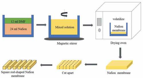
The thick Nafion membrane was prepared by solution casting, and then the square rod-shaped Nafion matrix was cut out by a sharp blade, as shown in . The specific preparation steps of the experiment are as follows: 24 ml Nafion solution and 12 ml dimethylformamide (DMF) solution were weighed and added into the silicon rubber mold with the size of 30 mm × 50 mm × 40 mm (length × width × height). The mixed solution was stirred by a magnetic stirrer for 3 hours and vibrated by ultrasonic for 1 hour, so that the two solutions were fully mixed. The mold containing the mixed solution was put into the incubator at 70°C for 46 h. Then, the incubator was closed and cooled naturally to room temperature. The solvent volatilizes continuously in the incubator, and the mixed solution crystallizes to form a film. The basement membrane was taken out and cut into some square rod-shaped Nafion matrices.
Figure 1. The fabrication of square rod-shaped Nafion membrane.
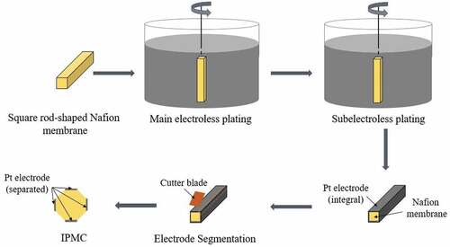
Platinum electrode layer was deposited on the surface of Nafion matrix by electroless plating, and four independent electrodes were manually separated, as shown in . The specific process is as follows: Each side of the square rod-shaped Nafion matrix were roughened with 800 mesh metallographic sandpaper for 10 min, and then was washed with deionized water to remove the impurities on the surface, and ultrasonicated for 30 minutes. The Nafion matrix was successively put into 2 wt% hydrochloric acid solution and heated in water bath at 80°C for 30 min to further remove the residual impurities in the matrix. After pretreatment, the square rod-shaped Nafion matrix was immersed in a certain concentration of Pt (NH3)4Cl2 solution for 14 h, and a proper amount of 5 wt% ammonia solution was added to prevent the hydrolysis of platinum ammonium ion. Using NaBH4 as a reducing agent, the platinum ammonium cations adsorbed in the Nafion matrix were reduced to platinum particles at a reaction temperature of 42–62°C. After the reaction is complete, the samples were taken out for cleaning and stored in 0.1 wt% hydrochloric acid solution. In order to obtain a more compact Pt metal layer, the samples were immersed in Pt(NH3)4Cl2 solution, and the secondary electroless plating was carried out with 1.5 wt% NH2OH·HCl and 20 wt% N2H4·H2O as reducing agent. After the reaction was complete, the samples were taken out for cleaning and stored in 0.1 wt% hydrochloric acid solution. The prismatic structure on the side of the square rod-shaped IPMC is convenient for manual cutting. The electrode is separated by using a sharp blade along the four prismatic edges of the IPMC so that they are not conductive to each other.
Figure 2. The fabrication and segmentation of IPMC electrodes.
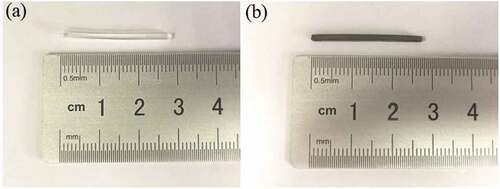
After electrode segmentation, the square rod-shaped IPMC was placed in LiCl and LiOH mixed solution and stored for 16 h, and the square rod-shaped IPMC with size of 1.35 mm × 1.55 mm × 28 mm (length × width × height) was successfully prepared, as shown in , which can realize multi-degree of freedom movement.
Figure 3. The images of Nafion and IPMC. (a) the square rod-shaped Nafion matrix; (b) the square rod-shaped IPMC.
3. Test apparatus
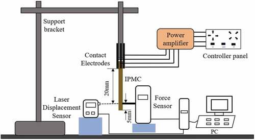
The driving performances of the square rod-shaped IPMC were measured on a test platform, including a signal generator, a force sensor (Q84X5X12-05Z-20 G, ZEMIC, China), and a laser displacement sensor (LK-GD500, KEYENCE, Japan), as shown in . The signal generator includes DC power supply (APS3500 S-3D, ATTEN, China), controller panel, power amplifier (DPA-1698, JUNTEK, China). 3 mm from one end of the square rod-shaped IPMC was fixed between four Cu electrodes, and the other end was suspended vertically. The laser displacement sensor and force sensor are used to test the output displacement and force at 5 mm of the other end of the square rod-shaped IPMC. Through the test platform, different voltage signal combinations can be applied to the two pairs of electrodes on the surface of the square rod-shaped IPMC, and the bending motion of the square rod-shaped IPMC in different directions can be realized, so as to complete the driving ability test of the square rod-shaped IPMC. Moreover, the resistance of the four surface electrodes of the square rod-shaped IPMC was measured using a digital multimeter (VC890D, VICTOR, China). The square rod-shaped IPMC was removed from deionized water and placed in a vacuum drying oven for 15 min to remove surface moisture. During the test, the distance between the two test points was kept to be 10 mm. Each surface electrode was measured three times, and the average value was finally calculated.
Figure 4. The schematic diagram of the test platform.
It is assumed that the square rod-shaped IPMC has a uniform curvature deformation relationship along the length direction after the voltage signal is applied [Citation26]. In this work, the relationship between the deflection angle at the end of the square rod-shaped IPMC and the displacement data d measured by the laser displacement sensor is obtained by means of trigonometric functions. Using the geometric relationship shown in and the following EquationEquations (1
(1)
(1) )–(Equation4
(4)
(4) ), the function between the bending angle
and the measured displacement d can be derived.
Figure 5. The diagram of angle derivation.
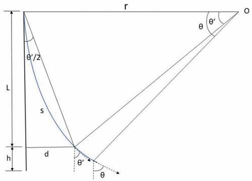
When L = 20 mm, h = 5 mm,
4. Results and discussion
4.1. The SEM observation and surface resistance test
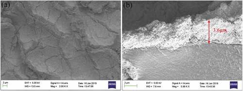
In order to study the Pt electrode on the surface of the square rod-shaped IPMC, the surface electrode morphology of IPMC samples was observed by scanning electron microscopy (SEM), as shown in . ) presents that the Pt electrode layer on the surface of the square rod-shaped IPMC is relatively flat, but there are also a few cracks for the easy migration of hydrated ions. In ), the thickness of Pt electrode is about 3.6 μm, and the Pt electrode layer and the base matrix are well bonded, generating enough electric field to drive the square rod-shaped IPMC. The results show that the average resistance of the four electrodes of the square rod-shaped IPMC is 3.5, 4.0, 3.8, 3.7 Ω/cm, respectively, which are lower enough and indicate that the conductivities of the four electrodes are excellent, reduce the voltage drop on the electrode surface, and are beneficial for IPMC behaviors.
Figure 6. The images of SEM. (a) surface electrode layer; (b) cross-sectional electrode layer.
4.2. Actuation behaviors
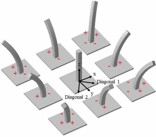
Different voltage signals are applied to the two pairs of electrodes on the surface of the square rod-shaped IPMC, respectively, which can realize the bending motion of the square rod-shaped IPMC in different directions, as shown in . By testing the displacement and blocking force of the square rod-shaped IPMC under different DC voltages, the influence of different voltages on driving performance of IPMC is analyzed. DC voltage signals of 2 V, 4 V, 6 V, and 8 V are selected to test the driving performance of the square rod-shaped IPMC. Due to water electrolysis, IPMC consumes some water in the process of voltage driving, which will affect the driving performance of IPMC. Therefore, in order to fully ensure the consistency of the square rod-shaped IPMC at different voltage signal, after each test it was immersed into deionized water for 1 h to make it fully replenish the water lost.
Figure 7. The motion sketch of the square rod-shaped IPMC.
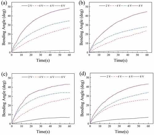
The displacement caused by the bending motion of the square rod-shaped IPMC was measured by the laser displacement sensor, and the bending angle of the square rod-shaped IPMC is calculated according to EquationEquation (4)(4)
(4) to verify whether the motion-guiding ability of the square rod-shaped IPMC meets the needs of the interventional catheter in the complex vascular system of the human body. shows the angle curves of the square rod-shaped IPMC changing with time in x, y, diagonal 1 and diagonal 2 directions under the DC voltage of 2 ~ 8 V. During the test time of 60 s, when the DC voltage signals are 2 V, 4 V, 6 V, and 8 V, respectively, the maximum displacements in the x direction were 0.32 mm, 3.97 mm, 5.15 mm, and 7.80 mm, respectively. The maximum bending angles were 2.26°, 27.37°, , and 48.50°, respectively. The maximum displacements in the y direction were 0.30 mm, 3.43 mm, 4.10 mm, and 7.01 mm, respectively. The maximum bending angles were 2.14°, 23.86°, , and 44.70°, respectively. The maximum displacements in the diagonal l direction were 0.97 mm, 4.07 mm, 5.06 mm, and 6.72 mm, respectively. The maximum bending angles were 6.91°, 27.96°, , and 43.22°, respectively. The maximum displacements in the diagonal 2 direction were 0.96 mm, 3.81 mm, 5.05 mm, and 6.69 mm, respectively. The maximum bending angles were 6.87°, 26.35°, , and 43.07°, respectively. It can be seen that, under the 8 V DC voltage signal, the maximum displacement of the square rod-shaped IPMC was 7.80 mm, and the maximum bending angle was up to 48.50°. The square rod-shaped IPMC has a good driving performance. Under the same DC voltage signal, the bending angle error of the square rod-shaped IPMC in all directions was kept within 5.5°. Therefore, the motion ability of the square rod-shaped IPMC in all directions has a good consistency. The end of square rod-shaped IPMC can successfully complete the semicircular motion under the control of external DC voltage signal, as shown in Movie S1.
Figure 8. The angle curves of the square rod-shaped IPMC under 2 ~ 8 V DC. (a) x-direction; (b) y-direction; (c) diagonal 1-direction; (d) diagonal 2-direction.
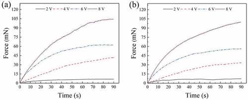
The blocking forces of the square rod-shaped IPMC in the direction of x, y, diagonal 1, diagonal 2 are measured by a force sensor. Under DC voltages of 2 V, 4 V, 6 V, and 8 V, respectively, the maximum blocking forces of the square rod-shaped IPMC in x direction were 7.90 mN, 33.34 mN, 71.75 mN, and 116.33 mN, respectively, while the maximum blocking forces in y direction were 6.48 mN, 31.37 mN, 71.97 mN, and 117.90 mN, respectively [Citation27]. In , the maximum output forces in diagonal 1 direction were 6.55 mN, 41.66 mN, 62.36 mN, and 104.07 mN, respectively, while the maximum blocking forces in the diagonal 2 direction were 7.03 mN, 33.63 mN, 55.57 mN, and 99.70 mN, respectively. As the DC voltage signal increases, the blocking force of the square rod-shaped IPMC increases gradually. Under the 8 V DC voltage signal, the maximum blocking force of the square rod-shaped IPMC can reach 117.90 mN. It can be seen that the blocking force is also significantly increased due to the significant increase of the thickness of the square rod-shaped IPMC compared with the conventional sheet IPMC.
Figure 9. The blocking force curves of the square rod-shaped IPMC under 2 ~ 8 V DC. (a) Diagonal 1-direction; (b) Diagonal 2-direction.
4.3. The simulation experiment
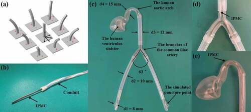
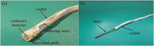
Nowadays, with the improvement of the living standards, the incidence of cardiovascular disease is also significantly increased. The most direct and effective method for cardiovascular disease is minimally invasive interventional surgery. Compared with the conventional interventional catheter, the active interventional catheter with active bending function can greatly save the operation time and reduce the operation risk. Based on the square rod-shaped IPMC, an interventional catheter which can realize the active guidance function was designed in this work. The interventional catheter mainly consists of a square rod-shaped IPMC, conductive electrodes, micro fixed guide, conduit, and conducting wires, as shown in . The square rod-shaped IPMC with the size of 1.45 mm × 1.55 mm × 25 mm (length × width × height) is selected as the front-end guide device of the interventional catheter, and it is closely combined with the micro fixed guide at the front-end of the catheter by means of interference fit. Among them, four wires with a diameter of 0.5 mm are selected to closely fit with four independent electrodes of the square rod-shaped IPMC. Through these four wires, different voltage signal combinations can be applied to the square rod-shaped IPMC, so as to realize the bending movement in different directions. Because the four wires have a certain supporting function in the catheter, the catheter maintains a certain rigidity and flexibility, and has better vascular adaptability. In the process of the in vitro simulation experiment of interventional surgery, the catheter can move forward and backward in the human vascular model by pushing and pulling action, which greatly reduces the operation difficulty of the simulation experiment.
Figure 10. The interventional catheter. (a) the front end of the catheter; (b) the side view of the catheter.
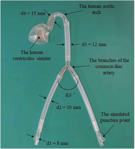
Because the position of human femoral artery is shallow, the internal diameter is relatively large and easy to operate, the current common path of cardiac interventional surgery is to use femoral artery puncture and intervention, through the external iliac artery, the common iliac artery, the abdominal aorta, the thoracic aorta, the aortic arch into the human heart, from which further angiography, stent placement and other treatment are carried out. Therefore, the branches of the common iliac artery and the human aortic arch constitute two barriers for the interventional catheter to enter the human heart. In order to better simulate the experiment of human aortic interventional surgery, a model of human aortic vascular that is close to the real size of human blood vessel was designed and the simulation experiment of interventional surgery in this model was completed. In order to simplify the difficulty of making the model and ensure that the accuracy of the intervention simulation experiment is not affected, all the inner diameter sizes of the vascular model are less than or equal to the average inner diameter sizes of the adult human vessels. The physical diagram of the vascular model is shown in .
Figure 11. The human aortic vascular model.
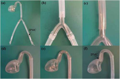
In this intervention simulation experiment, 6 V DC voltage signal was selected as the driving voltage signal of the square rod-shaped IPMC, and lubricating oil (WD-40 Multi Use, WD-40, USA) was applied to the main part of the interventional catheter to reduce the friction of the interventional catheter during the intervention simulation experiment. Before the intervention simulation experiment, the comparative experiments were carried out under the condition that the front end of the intervention catheter was equipped without the square rod-shaped IPMC as the guide device. The experimental results show that when there is no square rod-shaped IPMC at the front of the interventional catheter as the guiding device, the interventional catheter can’t smoothly enter the next vascular branch, as shown in Movie S2. Under the condition that the front end is equipped with the square rod-shaped IPMC as a guide device, the interventional catheter can smoothly pass through the iliac aortic branch and the aortic arch to enter the human left ventricle model smoothly with the guidance of the square rod-shaped IPMC, as shown in and Movie S3. The square rod-shaped IPMC is integrated into the front end of the interventional catheter to enter the vascular model from the simulated puncture intervention point. Under the action of external thrust, the interventional catheter is pushed forward continuously. When the square rod-shaped IPMC at the front of the interventional catheter reaches the iliac aortic branch, the external control circuit is used to apply a 6 V DC voltage signal to the square rod-shaped IPMC to make it bend to the upper right at a certain angle so that the interventional catheter can enter the next vascular access. Then, while pushing forward continuously, the reverse voltage signal is applied to control the square rod-shaped IPMC to restore a straight state. When the interventional catheter reaches the aortic arch successfully, voltage signals are applied to the square rod-shaped IPMC to make it produce bending deformation to adapt to the curvature of the aortic arch. Finally, the interventional catheter was continuously pushed forward, and the bending angle of the square rod-shaped IPMC was constantly adjusted through the external control circuit to make the interventional catheter reach the left ventricle of the human body smoothly. The simulation results showed that the interventional catheter could successfully reach the left ventricle of the human body through the complex and varied vascular pathways of the human aorta under the auxiliary guidance of the square rod-shaped IPMC. Therefore, the feasibility of the square rod-shaped IPMC in interventional catheters was verified.
Figure 12. The simulation experiment of interventional surgical operation. (a) the intervention at puncture point; (b) the guidance at branch of iliac aorta. (c) the IPMC restored to flat state; (d) the guidance at aortic arch; (e) angle adjustment and forward propulsion; (f) arrived the left ventricle.
5. Conclusions
In this work, the square rod-shaped IPMC with the size of 1.35 mm × 1.55 mm × 28 mm (length × width × height) was prepared. The bending motion of the square rod-shaped IPMC in multiple directions was realized. The preparation effect and driving performance of the square rod-shaped IPMC were tested. The results show that the Pt electrode on the surface of the square rod-shaped IPMC is deposited uniformly and has a low resistance. The experimental results show that the square rod-shaped IPMC has a good driving ability and realizes the semicircular motion under DC voltages. Under DC voltage of 8 V, the maximum bending angles were 48.50°, 44.70°, , and 43.07°, respectively, while the maximum blocking forces of the end were 116.33 mN, 117.90 mN, 104.07mN, and 99.70 mN, respectively. Based on the square rod-shaped IPMC, an interventional catheter with active guiding function was developed and the human aortic vascular model was built to complete the in vitro interventional simulation experiment. The experimental results show that the square rod-shaped IPMC, which can realize multi-degree of freedom bending motion, can well assist the interventional catheter to successfully complete the active guiding function in the vascular model, and verify the feasibility of the application of the square rod-shaped IPMC in the interventional catheter field.
Supplemental Material
Download MP4 Video (4.6 MB)Supplemental Material
Download MP4 Video (9.6 MB)Supplemental Material
Download MP4 Video (1.4 MB)Acknowledgments
The authors are deeply grateful for financial support from the Jiangsu Province Natural Science Foundation (Grant No. BK20160793), the National Natural Science Foundation of China (Grant No. 51605220), and Open Project Fund in Jiangsu Provincial Key Laboratory for Interventional Medical Devices (Grant No. jr1601).
Disclosure statement
No potential conflict of interest was reported by the authors.
Supplemental Material
Supplemental data for this article can be accessed here.
Correction Statement
This article has been republished with minor changes. These changes do not impact the academic content of the article.
Additional information
Funding
Related Research Data
References
- Jo C, Pugal D, Oh IK, et al. Recent advances in ionic polymer-metal composite actuators and their modeling and applications. Prog Polym Sci. 2013;38:1037–1066.
- Carrico JD, Hermans T, Kim KJ, et al.. 3D-printing and machine learning control of soft ionic polymer-metal composite actuators. Sci Rep. 2019;9: 174821–17.
- Wang YJ, Liu JY, Zhu YT, et al. Formation and characterization of dendritic interfacial electrodes inside an ionomer. ACS Appl Mater Inter. 2017;9:30258–30262.
- Palmre V, Kim SJ, Pugal D, et al. Improving electromechanical output of IPMC by high surface area Pd-Pt electrodes and tailored ionomer membrane thickness. Int J Smart Nano Mater. 2014;5:99–113.
- Sun Z, Yang L, Zhang D, et al. High performance, flexible and renewable nano-bio composite artificial muscle based on mesoporous cellulose/ionic liquid electrolyte membrane. Sensor Actuat B-Chem. 2019;283:579–589.
- Zhu ZC, Bian CS, Ru J, et al. Rapid deformation of IPMC under a high electrical pulse stimulus inspired by action potential. Smart Mater Struct. 2019;28:01LT01(6pp).
- Shen Q, Kim KJ, Wang T. Electrode of ionic polymer-metal composite sensors: modeling and experimental investigation. J Appl Phys. 2014;115(19): 1949021–14.
- Feng GH, Tsai JW. Micro-machined optical fiber enclosed 4-electrode IPMC actuator with multidirectional control ability for biomedical application. Biomed Microdevices. 2011;13:169–177.
- Guo S, Shi L, Xiao N, et al. A biomimetic underwater microrobot with multifunctional locomotion. Rob Autom Syst. 2012;60:1472–1483.
- He QS, Liu ZG, Yin GX, et al. The highly stable air-operating ionic polymer metal composite actuator with consecutive channels and its potential application in soft gripper. Smart Mater Struct. 2020;29:045013(13pp).
- Najem J, Sarles SA, Akle B, et al. Biomimetic jellyfish-inspired underwater vehicle actuated by ionic polymer metal composite actuators. Smart Mater Struct. 2012;21:094026(11pp).
- Tiwari R, Kim KJ. Mechanoelectric transduction in ionic polymer-metal composite. Appl Phys Lett. 2013;102:1239031–1239034.
- Anand SV, Arvind K, Bharath P, et al.. Energy harvesting using ionicelectro-active polymer thin films withAg-based electrodes. Smart Mater Struct. 2010;19: 0450261–7.
- Chang LF, Liu YF, Yang Q, et al. Ionic electroactive polymers used in bionic robots: a review. J Bionic Eng. 2018;15:765–782.
- He QS, Yang X, Wang ZY, et al. Advanced electro-active dry adhesive actuated by an artificial muscle constructed from an ionic polymer metal composite reinforced with nitrogen-doped carbon nanocages. J Bionic Eng. 2017;14:567–578.
- Liu H. A study on the catheter guiding device for invasive surgery [Master diss.]. Harbin Industrial University; 2006.
- Mineta T, Mitsui T, Watanabe Y, et al. Batch fabricated flat meandering shape memory alloy actuator for active catheter. Sensor Actuat A-Phys. 2001;88:112–120.
- Guo S, Fukuda T, Kosuge K, et al. Micro catheter system with active guide wire. Rob Autom. 1995;1:79–84.
- Fang BK, Ju MS, Lin CCK. A new approach to develop ionic polymer-metal composites (IPMC) actuator: fabrication and control for active catheter systems. Sensor Actuat A-Phys. 2012;137(2):321–329.
- Fang B-K, Lin C-CK, Ju M-S. Development of sensing/actuating ionic polymer–metal composite (IPMC) for active guide-wire system. Sensors and Actuators A: Physical. 2010;158(1):1–9.
- Biswal DK. Development of an Active Catheter Mechanism using IPMC for in vivo Inspection. Int J Mechatroni Autom. 2015;119(34):1–10.
- Ruiz S, Mead B, Palmre V, et al. A cylindrical ionic polymer-metal composite-based robotic catheter platform: modeling, design and control. Smart Mater Struct. 2015;24(1):015007(11pp).
- Marissa A, James D, Kim KJ, et al. Slender tube-shaped and square rod-shaped IPMC actuators with integrated sensing for soft mechatronics. Meccanica. 2015;50:2781–2795.
- Stalbaum T, Pugal D, Nelson SE, et al. Physics-based modeling of mechano-electric transduction of tube-shaped ionic polymer-metal composite. J Appl Phys. 2015;117:15–30.
- Kim SJ, Pugal D, Wong J, et al. A bio-inspired multi degree of freedom actuator based on a novel cylindrical ionic polymer–metal composite material. Rob Autom Syst. 2014;62:53–60.
- Kim SJ, Pugal D, Jung Y, et al. A rod-shaped ionic polymer-metal composite for use as an active catheter-platform. Proceedings of the ASME 2010 Conference on Smart Materials, Adaptive Structures and Intelligent Systems. Philadelphia; 2010.
- Huo K, He QS, Yin GX, et al. Fabrication and driving performance of square rod-shaped ionic polymer-metal composites. J Funct Mater. 2019;9:09013–09026.