
 ?Mathematical formulae have been encoded as MathML and are displayed in this HTML version using MathJax in order to improve their display. Uncheck the box to turn MathJax off. This feature requires Javascript. Click on a formula to zoom.
ABSTRACT
Leveraging advances in shape memory alloys (SMAs) and flexible thermoelectric devices (f-TEDs), this paper presents a structural and functional integrity composite sheet to address the inefficient and bulky activation of 2-D SMAs. A series of experimental tests were performed to reveal the generation, change, and transfer mechanisms of different types of electrically-induced heat in the f-TED, as well as the temperature-induced SMA phase transformation behaviors. The results show that the composite sheet exhibited good bidirectional thermal management capacity. The austenite deformation can be completed within 10s at an operating current of 2 A. The cooling recovery, in particular, performs much better than in conventional modes (the temperature declines exponentially with time). Finally, through two functional prototypes, a light switch and a flexible gripper, the application potential of the proposed composite was further experimentally demonstrated.
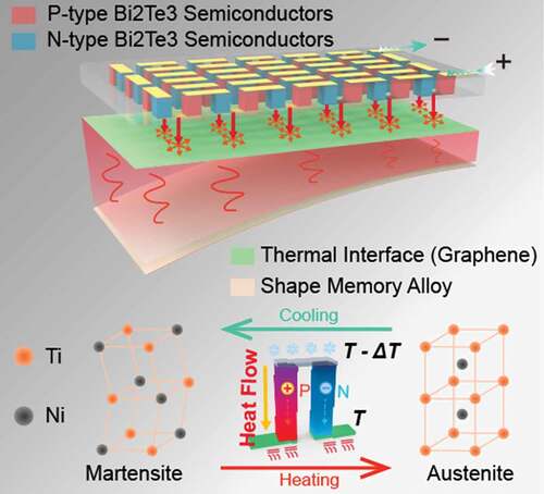
Graphical Abstract
1. Introduction
As an intelligent material, shape memory alloys (SMAs) can convert electrical and thermal energy into mechanical energy [Citation1] under external stimuli. Compared to traditional actuators (such as electrical motors, air pumps, and hydraulic cylinders), the shape memory alloys can reduce the size and complexity of the mechanisms owing to their high work-to-weight ratio. They have, therefore, become widely used in soft robots [Citation2–5], actuators [Citation6–8], medical devices [Citation9,Citation10], artificial muscles [Citation11,Citation12], and aerospace [Citation13,Citation14].
Wires or their variants (e.g. spring coils) are the most common form of the existing SMA actuators. In addition to being simple to fabricate or assemble [Citation11,Citation15,Citation16], the fundamental reason is that the wires can be easily activated by electrical heating [Citation17]. However, the one-dimensional configuration is difficult to be used directly as functional structures, but instead, as discrete actuators or in combination with other structures [Citation18,Citation19]. Two-dimensional configurations (e.g. thin sheets) can address this problem by richer deformation patterns. If so, ideal compact, flexible and programmable SMA-based intelligent structures could be developed (e.g. fabricated by additive manufacturing techniques [Citation5,Citation20]). Unfortunately, the SMA sheets cannot convert electrical energy effectively into Joule heat because of their minimal resistance values. In the literature [Citation5,Citation21,Citation22], NiCr wires were wrapped densely around SMA sheets, and the Joule heat generated by the wires was transferred to the SMA structures. However, this solution has a certain amount of heat loss (the insulating layer of the wire conducts heat poorly) and tends to cause uneven heating. Thabuis et al. used an electromagnetic induction to heat the SMA with complex shapes [Citation23]. This approach requires the location of a fixed heating device that must match the geometry of the SMA structure, thus leading to more complexity and less flexibility in the construction process.
In addition, unlike Cu-based SMAs [Citation24–26], the most commonly used NiTi SMAs have heat dissipation problems. To rely on natural heat dissipation does often take too long. Forced convection cooling [Citation27,Citation28] or liquid cooling circulation systems [Citation29] are currently used to increase heat dissipation. However, forced convection can only enhance heat dissipation rate to a limited extent, while the liquid cooling method requires a complex and bulky set of equipment. Therefore, more convenient and efficient cooling solutions are key for the SMA actuators.
Thermoelectric devices (TEDs) based on the Peltier effect have shown the capability to transport heat from one side to the other [Citation30]. The TED is unique for SMA’s temperature management since it can integrate heating and cooling in a single system. There has been some relevant research [Citation31–33] on this topic, but the benefits of TEDs are not yet fully demonstrated. Traditional TEDs they used are composed of non-flexible substrates. Therefore, the traditional TEDs cannot deform along with SMAs. Flexible thermoelectric devices [Citation34] (f-TEDs) have been developed in recent years because of the advancement in flexible electronics. They have been used in wearable devices [Citation35,Citation36], for power generation [Citation37,Citation38], for the sharing of thermal information [Citation39], and in variable stiffness actuators [Citation40]. The f-TEDs have significant flexibility and adapt quite well to structural deformation, showing their potential in the efficient activation of SMAs.
This paper proposes a binary composite structure consisting of an SMA sheet and an f-TED compliantly bonded on it. Two active thermal modes can be easily switched during its operation, thanks to the Peltier effect of the f-TED. The composite sample was designed and fabricated using a cost-effective method and then experimentally tested its two-way performance under different operating conditions. The conversion and coupling behavioral mechanism among the different energy forms (electrical, thermal, and mechanical) was quantitatively measured and analyzed. At last, two applications were presented, further demonstrating the feasibility of the smart composite.
2. Materials and methods
2.1. Functional structure design
The proposed f-TED/SMA (f-TES) composite comprises a two-way shape memory alloy (TWSMA) sheet, a graphene sheet, and an f-TED ()). The heat sink is an optional part of improving the cooling performance of the composite, and it will be further described in the next section. The Ni55Ti45 (wt.%) TWSMA sheet (Haichuan Rare Metal Products Co., China) can switch between two featured shapes (at high and low temperatures) [Citation41]. In order to better demonstrate the performance of bidirectional heat management, TWSMA was selected in this paper. However, the two-way shape memory effect will lose after too much cyclic loading. A more stable actuation scheme (a one-way shape memory alloy sheet and a spring) is shown in the supplementary material. The f-TED performs the heat management function, and it works on the principle of the Peltier effect. In this study, p-type (Bi0.5Sb1.5Te3) and n-type (Bi2Te2.7Se0.3) thermoelectric legs (TE legs) were used to form a circuit based on the Peltier effect. When a current is applied, heat is transferred from one side of the f-TED to the other ()). One side of the f-TED will become cold, and the other side will be hot. Furthermore, switching the current direction will change the direction of the heat transfer. The graphene sheets are used in the composite structure to improve heat transfer efficiency.
Figure 1. a) A schematic diagram of the f-TES composite. b) The principle of the Peltier effect. c) An f-TES composite that is bent by hand. The bending radius is ~23 mm. d) Clamping conditions and characteristic deformation states. e) Steps in the f-TED construction.
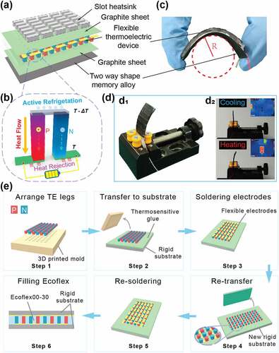
A 0.25 mm thick SMA sheet is bonded to an f-TED, with a graphene sheet in between. These layers are bonded by a highly thermally conductive (2 W•m−1•K−1) silicone glue (K5205, Kafuter, China). It is worth noting that the poor ductility of the graphene sheet will affect the flexibility of the final f-TES composite. In order to reduce the deformation hindrance, the graphite sheet has been cut into several short segments (at equal intervals along the width direction). The resulting composite has an overall dimension of 40 mm × 20 mm × 2.2 mm, and a total weight of 4.72 g. The composite can be made highly flexible by designing appropriate structural parameters ()). ) shows the operating state of the composite sheet, bending in the heating mode and recovering back, to a flat state, in the cooling mode. These states depend entirely on the current phase of the SMA.
2.2. Fabrication of the f-TED
) shows the steps in the f-TED fabrication. Step 1: TE legs (1.3 mm × 1.3 mm × 1.5 mm) were arranged on a 3D printed mold with row and column spacings of 1.5 mm. Step 2: A rigid substrate with a thermosensitive adhesive was snapped onto the top of the TE legs. The entire device was turned upside-down, and the 3D-printed mold was removed. The transfer of the TE legs to the substrate was, thereby, completed. Step 3: Solder paste (Sn42Bi58 solder paste) was applied to the top of the TE legs. Then, the TE legs were sequentially bridged by 0.06 mm thick copper foils and bonded through a high-temperature re-flow soldering machine. Step 4: A second substrate, coated with a new thermosensitive adhesive, was snapped onto the top of the TE legs bonded with copper foils. Again, the entire device was turned upside-down. The first attached substrate (see step 2) was easily removed as the adhesive strength of the thermosensitive adhesive decreased after high-temperature treatment. Step 5: There was a repetition of step 3. Step 6: Silicone rubber was filled into the gaps of the TE legs. After the silicone rubber was cured, remove the substrates to get the f-TED.
2.3. Phase change temperature test
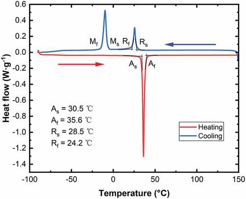
With temperature changes, SMA undergoes mutual alteration between martensite (M-phase) and austenite (A-phase). The obtained SMA is mainly affected by the processing steps, and there is an intermediate phase called the rhombohedral phase (R-phase). In the present study, the temperature range has been set to the R-to-A phase transition temperature interval. This choice of temperature interval is based on the fact that the hysteresis effect is relatively more minor as the A-phase transitions to the R-phase rather than the M-phase upon cooling (). As shown in , the phase transition temperature of the SMA sheet was measured by a differential scanning calorimetry (DSC). As and Af represent the beginning and end of the A-phase transformation temperatures, respectively, and Rs and Rf represent the beginning and end of the R-phase transformation temperatures.
Figure 2. DSC measurement results of the SMA sheet.
3. Results and discussion
3.1. Heating mode of the f-TES Composite
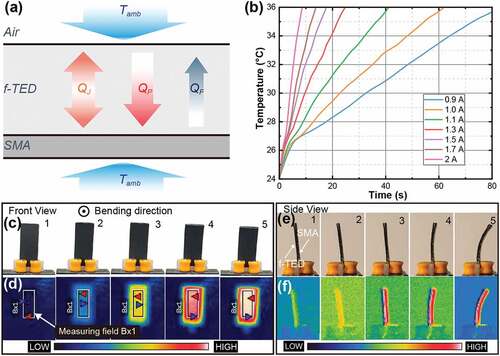
As shown in ), when the f-TES composite is operating in the heating mode, the surface will be hot where the f-TED and the SMA sheet fit together. The heat flow into the hot surface is defined as positive and can be written as [Citation42]:
Figure 3. a) Heat transfer sketch of the f-TES composite in the heating mode. b) The rise in SMA temperature at different currents. c-f) Pictures and thermal images of the heating Bend of the f-TES composite (from a front- and side-view).
where QJ is the Joule heat, QP is the Peltier heat, QF is the Fourier heat, I is the applied current to the f-TED, R is the total resistance of the f-TED, N is the number of thermoelectric legs, α is the Seebeck coefficient for the thermoelectric legs, k is the effective thermal conductivity of the f-TED in the z-direction, and Th and Tc are hot and cold side surface temperatures, respectively.
The Joule heat and Peltier heat positively influence the heating effect of the f-TED according to the EquationEquation (1)(1)
(1) , while the Fourier heat harms this heating effect. The Fourier heat has only a significant effect when the temperature difference reaches a certain level. Therefore, the average temperature in the test area of the SMA surface will rise as the current increases ()). The temperature of the SMA was measured by an infrared camera (FLIR E40, Teledyne FLIR, USA). The heating time it takes to go from room temperature (24°C) to Af is less than 10 seconds at 2A current, which is a significant heating rate.
Disregarding the thermal resistance between f-TED and the SMA sheet, the heat flow, Qh, generated by f-TED will be entirely absorbed by the SMA sheet. Before the start of the A-phase transformation, the heat input only changes the internal energy of the SMA. Furthermore, when the A-phase transformation starts, one needs to consider the latent heat of the phase transformation [Citation43]. The equation of the energy change can be written as:
where m is the mass of the SMA sheet, cp is the heat capacity of the SMA sheet, Δh is the enthalpy change during phase transition, and ξ is the volume fraction of the R-phase. ξ is temperature-dependent, and further details will be discussed further below.
As EquationEquation (2)(2)
(2) , the SMA consumes a part of the heat provided by the f-TED for its phase transition. The temperature increase will, therefore, slow down to a certain extent. As shown in , the temperature curve of the SMA has a large linear slope before reaching ~ 27°C. The rate of temperature rise slows down above 27°C. It can be concluded that the phase transition starts at ~ 27°C. For detailed information about the effect of phase transition on the temperature curve, see the relevant work [Citation44]. As the current increases, the slope of the temperature curve rises, both before and after the breakpoint (~ 27°C). The slope approximates a straight line for an input current as large as 1.5 A.
The internal crystal structure of the SMA switches from R-phase to A-phase when the temperature reaches As, which leads to the composite bending. ) shows the bending process of the f-TES composite (from the perspective of the orthogonal SMA surface). The corresponding thermal images are shown in ). The central region of the SMA sheet, which corresponds to the effective region enclosed by the flexible electrodes, produces a uniform temperature field because of the excellent in-plane thermal conductivity (1100 ~ 1300 W•m−1•K−1) of the graphene sheet. This area (i.e. Bx1) has been chosen as the measurement area. The largest temperature difference between any two sites in the Bx1 area does not exceed 1°C during the whole heating process. However, considering the temperature in the edge and thickness direction, the temperature of SMA is not homogenous. Pictures and thermal images of the composite (side views) are shown in ). The heat gradually shifts from the left side of the device to the right side. Moreover, the temperature gradient becomes more significant during the energization period in the same direction.
3.2. Cooling mode of the f-TES Composite
After the heating has been completed, changing the current direction, and the composite is switched to cooling mode. In this mode, the Peltier heat flows in the reverse direction to lower the temperature of the SMA. The internal crystal structure of the SMA will, thereby, transform from an A-phase to an R-phase, and the SMA sheet will drive the composite to recover its flat form. ) demonstrates the recovery process of the f-TES composite, and the corresponding thermal imaging is shown in ). Temperature uniformity in the surface of the SMA sheet remains good, with an overall decrease in temperature. ) shows the side views of structural deformation. The right part of these side-views is the SMA sheet, while the left part is the f-TED. The thermal images show that the red high-temperature part of the f-TES (i.e. the SMA) shifts to the left with time, while the temperature of the SMA turns blue ()).
Figure 4. a-d) Pictures and thermal images of the f-TES composite in the cooling mode (from a front- and a side-view). e) Heat dissipation curves for the SMA at different currents. f) Cooling time versus current.
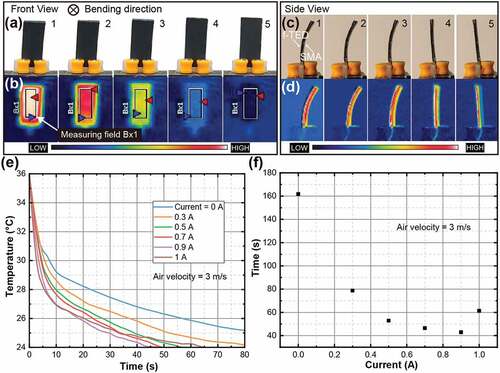
For the cooling experiments, the SMA was firstly heated to 36°C using a current of 1 A. Then the effect of different currents was then investigated at a wind speed of 3 m/s ()). The first test was conducted in the absence of an input current. Thus, the heat dissipation depended on thermal convection caused by the airspeed. The SMA sheet takes 161.8 seconds (temperature-dependent) to return to room temperature (24°C). However, the cooling recovery time was reduced to half of its original value (about 80s) with only a small current of 0.3 A. Also, when increasing the current to 0.5 A, the cooling recovery time was further reduced (to about 55s). It was clear that the Peltier effect had a significant impact on the heat dissipation performance of the SMA.
As the current increases to a certain extent, the heat dissipation capacity of the composite actuator turns to deteriorate. For example, when the current is further increased to 1 A, the required cooling time is ~ 65s. which is longer than the one observed in a current of 0.9 A (i.e. 42.9 s). It can be explained from the thermal analysis. After the switch of the input current, the heat flowing into the cold side of the f-TED (i.e. the side connected with the SMA sheet) can be expressed as:
the parameters, in this equation, are described in the previous sections.
According to the EquationEquation (3)(3)
(3) , the Peltier heat has a positive effect on the cooling function of the composite, while the Joule heat and the Fourier heat have a reverse effect. The magnitude of the effect of the Fourier heat depends on the temperature difference between the hot and cold surfaces. However, for the hot surface, the rate of heat dissipation does not match the heat input rate, which means that Th will increase during the process. The heat accumulation, thereby, inhibits the cooling effect of the cold surface. Obviously, the higher the operating current, the larger the suppressive effect of the Joule heat and the Fourier heat. Thus, for a current of 1 A, the cooling time will instead increase. If the current continues to increase, the cooling time will further increase and even fail to restore the temperature of the SMA to room temperature.
An increasing heat transfer coefficient, between the hot surface and the air, will improve the cooling effect of the f-TES composite [Citation45]. The proposed structure design allows us to further improve its thermal performance by attaching a heat sink (consisting of 1.5 mm × 4.5 mm × 2 mm aluminum particles) to its surface. ) shows the thermal performance curves of the f-TES composite with an attached heat sink. The air-cooling conditions are the same as for the f-TES composite without any heat sink. The cooling time becomes smaller as the current increases. Up to the operating limit current of 2 A, the composite with heat sink does not show any deterioration in cooling performance. In fact, the cooling time is as short as 5.6 s for an input current of 2 A, which is 93.7% shorter than the cooling time (88.2 s) obtained without any current. The result shows the heat sink can effectively improve the Peltier cooling effect. It is worth mentioning that the heat sink also has side effects. There is a geometrical incompatibility between the surfaces of the heat sink and the composite actuator, so the output deformation of the composite actuator is limited.
Figure 5. Factors improving the cooling performances of the f-TES composite. a) Tests in operation currents after adding a heat sink. b) Tests at different air velocities for a 1 A operating current.
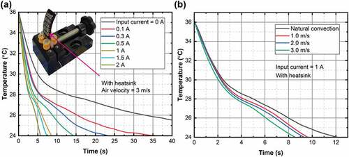
The air velocity also affects the heat dissipation performance of the f-TES composite ()). The cooling time will decrease as air velocity increases under a 1 A operational current. However, the reduction in cooling time is not significant.
3.3. Actuation of the composite
The f-TES composite without any heat sink is utilized to investigate the actuation of the device in the following way. With one end held fixed and the other free, the device is kept vertically on a base. A bending angle describes the deformation of the device ()). A heating current of 1 A is initially provided to the device, followed by a cooling current of 0.9 A to complete a single cycle of motion (Supplementary Video S1). The bending angle and angular velocity are acquired by image processing, and we use the zero line of angular velocity as a reference to separate the single-cycle deformation into four stages ()).
Figure 6. Kinetic testing of the f-TES composite. a) Definition of the bending angle, which is formed between the line connecting the free end (target point) and the fixed end (origin), and the vertical reference line. b) Time evolution of the bending angle and angular velocity. The angular velocity over the complete time span can be separated into 4 stages. M1: forward deformation stage, S1: end of bending deformation stage, M2: reverse deformation stage, and S2: end of reverse deformation stage. c) Evolution of the volume fraction of the temperature-induced R-phase. d) Blocking force test.
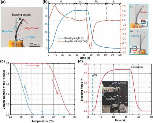
The deformation of the composite actuator is caused by the phase transition of the SMA sheet. Neglecting the small interfacial stresses during bending deformation of the composite, the phase transformation of the SMA is completely induced by the temperature. The relationship between the volume fraction of the internal R-phase (ξR) and the temperature (T) can be described as [Citation46]:
CONVERSION TO AUSTENITE
where, .
CONVERSION TO R-PHASE
where, .
) shows that the ξR decreases from 1 to 0 with increased temperature, indicating that the R-phase structure disappears in the transformation into austenite. Then, the ξR rises back to 1 as the temperature decreases, indicating that the austenite structure gradually transforms to the R-phase.
The velocity curve in ) shows that the reverse phase transition is faster than the forward. The average angular velocity, measured for the forward deformation, is 0.6 °/s, while the reverse deformation value is 0.8 °/s. This result can be explained by the fact that the absorbed energy that is required for the forward deformation is larger than the energy released during the reverse deformation of the SMA. The DSC curve in shows that the area of the forward heating peak, SA, is larger than the area of the reverse cooling peak, SR.
The discussion above is valid for the case where the composite is free to deform. However, when there is an external load applied to the composite, the output of the composite will be a force. ) shows the experimental setup and the results of the blocking force test. The blocking force increased with the input of a heating current of 1 A, and the maximum force was 2.2 N. The blocking force was measured using a force sensor (9301B, Kistler, Germany). In addition, the output force of the f-TES composite decreased as a response to a reverse input of a cooling current of 0.9 A.
3.4. Case study
The composite actuators without the heat sink were used in the case study. ) demonstrates the usage of the f-TES composite as a switch. The copper foil is attached to the end of the device and the black base. In addition, the wires on the copper foil connect via the customized led lights to the power supply. When the f-TES composite actuator is heated and bent (heating time: 10s), the two copper foils come into contact, causing the circuit to turn on and led to light up. However, when the f-TES composite switches to the cooling mode (cooling time: 10s), it starts to recover and causes the circuit to break and lead to light off (see Video S2 in Supplementary Information).
Figure 7. Two examples of applications for the f-TES composite. a) Switch to control the LED. b) Gripper to catch and release objects.
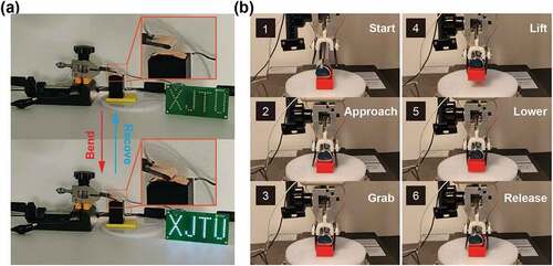
Two f-TES composite sheets form a pair of forceps ()). The two devices are connected in series to the circuit to complete the opening and closing control of the forceps (heating/cooling time: 20s). The forceps targets are a red carrier and a weight. The total weight of the forceps targets is 106 g, which is 11 times the weight of the two composite sheets. The following is the procedure for the forceps in action. At first, the forceps will gradually approach the target from an initial position and reach an optimal position. Then, the two f-TES composites are heated and, thereby, bent to grasp the target. The target is lifted to a certain height and then lowered to a position close to the bottom platform. Finally, the two f-TES composites are cooled and restored to flatness, and the target drops to the ground platform (see Video S3 in Supplementary information).
4. Conclusion
A bidirectional thermal management method for SMA sheets, in combination with an f-TED, has been developed and constructed in the present study. The proposed composite has two temperature control modes (i.e. heating and cooling), corresponding to bending and recovering flat form. Moreover, f-TED can closely fit and deform along with the SMA sheet. Thus, the f-TED can always control the global temperature of the SMA and, thereby, improve the driving efficiency. In particular, the cooling rate of the SMA can be significantly improved. However, the f-TED and the graphene is not ductile, making it difficult to be applied to situations requiring large curvature bending, or stretching deformation. The polymer thermoelectric materials might be a solution [Citation30].
Although only SMA sheets have been investigated in the present study, the simple composite approach allows the f-TED to be extended to other SMA actuators with complex structures. By bonding the f-TEDs to key actuation areas and controlling them time-sharing, SMAs with complex structures can perform special actions. Furthermore, the combination of antagonistic structure and active temperature control technology proposed in this paper would further improve the response speed of the SMA actuators. There are two commonly used antagonistic structures: bias springs or two smart materials (see supplementary material). In conclusion, the f-TED-based flexible actuation is particularly important in solving the problem of SMA structure design limitations and expanding the application prospects of SMAs.
Supplemental Material
Download MP4 Video (8.1 MB)Supplemental Material
Download MP4 Video (3.4 MB)Supplemental Material
Download MP4 Video (3.1 MB)Supplemental Material
Download MS Word (809.3 KB)Disclosure statement
No potential conflict of interest was reported by the author(s).
Supplementary material
Supplemental data for this article can be accessed online at https://doi.org/10.1080/19475411.2022.2076754
Additional information
Funding
Related Research Data
References
- Mohd Jani J, Leary M, Subic A, et al. A review of shape memory alloy research, applications and opportunities. Mater Des. 2014;56:1078–1113.
- Velvaluri P, Soor A, Plucinsky P, et al. Origami-inspired thin-film shape memory alloy devices. Sci Rep. 2021;11:10988.
- Coral W, Rossi C, Curet OM, et al. Design and assessment of a flexible fish robot actuated by shape memory alloys. Bioinspir Biomim. 2018;13:056009.
- Laschi C, Cianchetti M, Mazzolai B, et al. Soft robot arm inspired by the octopus. Adv Robot. 2012;26:709–727.
- Yao T, Wang Y, Zhu B, et al. 4D printing and collaborative design of highly flexible shape memory alloy structures: a case study for a metallic robot prototype. Smart Mater Struct. 2020;30:015018.
- Lee HT, Seichepine F, Yang GZ. Microtentacle actuators based on shape memory alloy smart soft composite. Adv Funct Mater. 2020;30:2002510.
- Huang X, Kumar K, Jawed MK, et al. Chasing biomimetic locomotion speeds: creating untethered soft robots with shape memory alloy actuators. Sci Robot. 2018;3:eaau7557.
- Zhakypov Z, Mori K, Hosoda K, et al. Designing minimal and scalable insect-inspired multi-locomotion millirobots. Nature. 2019;571:381–386.
- B MN. Medical shape memory alloy applications—the market and its products. Mater Sci Eng A. 2004;378:16–23.
- Li S, Kim Y-W, Choi M-S, et al. Superelasticity, microstructure and texture characteristics of the rapidly solidified Ti–Zr–Nb–Sn shape memory alloy fibers for biomedical applications. Mater Sci Eng A. 2022;831:142001.
- Wang W, Ahn S-H. Shape memory alloy-based soft gripper with variable stiffness for compliant and effective grasping. Soft Robot. 2017;4:379–389.
- Huang X, Kumar K, Jawed MK, et al. Highly dynamic shape memory alloy actuator for fast moving soft robots. Adv Mater Technol. 2019;4:1800540.
- Oliveira JP, Shen J, Escobar JD, et al. Laser welding of H-phase strengthened Ni-rich NiTi-20Zr high temperature shape memory alloy. Mater Des. 2021;202:109533.
- Shen J, Zeng Z, Nematollahi M, et al. In-situ synchrotron X-ray diffraction analysis of the elastic behaviour of martensite and H-phase in a NiTiHf high temperature shape memory alloy fabricated by laser powder bed fusion. Addit Manuf Lett. 2021;1:100003.
- Liang C, Wang Y, Yao T, et al. A shape memory alloy-actuated soft crawling robot based on adaptive differential friction and enhanced antagonistic configuration. J Intell Mater Syst Struct. 2020;31:1920–1934.
- Mc Caffrey C, Umedachi T, Jiang W, et al. Continuum robotic caterpillar with wirelessly powered shape memory alloy actuators. Soft Robot. 2020;7:700–710.
- Motzki P, Gorges T, Kappel M, et al. High-speed and high-efficiency shape memory alloy actuation. Smart Mater Struct. 2018;27:075047.
- Han M-W, Kim M-S, Ahn S-H. Shape memory textile composites with multi-mode actuations for soft morphing skins. Compos Part B Eng. 2020;198:108170.
- Kim H-I, Han M-W, Song S-H, et al. Soft morphing hand driven by SMA tendon wire. Compos Part B Eng. 2016;105:138–148.
- Ke WC, Oliveira JP, Cong BQ, et al. Multi-layer deposition mechanism in ultra high-frequency pulsed wire arc additive manufacturing (WAAM) of NiTi shape memory alloys. Addit Manuf. 2022;50:102513.
- Paik JK, Hawkes E, Wood RJ. A novel low-profile shape memory alloy torsional actuator. Smart Mater Struct. 2010;19:125014.
- She Y, Li C, Cleary J, et al. Design and fabrication of a soft robotic hand with embedded actuators and sensors. J Mech Robot Trans ASME. 2015;7:021007.
- Thabuis A, Thomas S, Martinez T, et al. Designing compliant mechanisms composed of shape memory alloy and actuated by induction heating. Smart Mater Struct. 2021;30:095025.
- Oliveira JP, Crispim B, Zeng Z, et al. Microstructure and mechanical properties of gas tungsten arc welded Cu-Al-Mn shape memory alloy rods. J Mater Process Technol. 2019;271:93–100.
- Oliveira JP, Zeng Z, Berveiller S, et al. Laser welding of Cu-Al-Be shape memory alloys: microstructure and mechanical properties. Mater Des. 2018;148:145–152.
- Oliveira JP, Zeng Z, Omori T, et al. Improvement of damping properties in laser processed superelastic Cu-Al-Mn shape memory alloys. Mater Des. 2016;98:280–284.
- Mao Z, Xu Z, Wang Q. Shape memory alloy actuator with active cooling device and deflectable winglet application. Smart Mater Struct. 2020;29:105026.
- Borboni A, Faglia R, Palpacelli M. 2014. Shape memory actuator with slider and slot layout and single fan cooling. 2014 IEEE/ASME 10th International Conference on Mechatronic and Embedded Systems and Applications (MESA). Senigallia, Italy; pp. 1–6.
- Cheng SS, Kim Y, Desai JP. Modeling and characterization of shape memory alloy springs with water cooling strategy in a neurosurgical robot. J Intell Mater Syst Struct. 2017;28:2167–2183.
- Du Y, Xu J, Paul B, et al. Flexible thermoelectric materials and devices. Appl Mater Today. 2018;12:366–388.
- Luo Y, Takagi T, Maruyama S, et al. A shape memory alloy actuator using peltier modules and R-Phase transition. J Intell Mater Syst Struct. 2000;11:503–511.
- Selden B, Cho K, Asada HH. Segmented shape memory alloy actuators using hysteresis loop control. Smart Mater Struct. 2006;15:642–652.
- Lantada AD, Morgado PL, Sanz JLM, et al. Intelligent structures based on the improved activation of shape memory polymers using Peltier cells. Smart Mater Struct. 2010;19:055022.
- Shi X-L, Zou J, Chen Z-G. Advanced thermoelectric design: from materials and structures to devices. Chem Rev. 2020;120:7399–7515.
- Kim CS, Lee GS, Choi H, et al. Structural design of a flexible thermoelectric power generator for wearable applications. Appl Energy. 2018;214:131–138.
- Hong S, Gu Y, Seo JK, et al. Wearable thermoelectrics for personalized thermoregulation. Sci Adv. 2019;5:eaaw0536.
- Dargusch M, Liu W-D, Chen Z-G. Thermoelectric generators: alternative power supply for wearable electrocardiographic systems. Adv Sci. 2020;7:2001362.
- Bahk J-H, Fang H, Yazawa K, et al. Flexible thermoelectric materials and device optimization for wearable energy harvesting. J Mater Chem C. 2015;3:10362–10374.
- Kim S, Kim T, Kim CS, et al. two-dimensional thermal haptic module based on a flexible thermoelectric device. Soft Robot. 2020;7:736–742.
- Kim CS, Oh OK, Choi H, et al. Variable rigidity module with a flexible thermoelectric device for bidirectional temperature control. Soft Robot. 2021;8:662–672.
- Liu Y, Liu Y, Van Humbeeck J. Two-way shape memory effect developed by martensite deformation in NiTi. Acta Mater. 1998;47:199–209.
- Min G, Rowe DM. Improved model for calculating the coefficient of performance of a Peltier module. Energy Convers Manag. 2000;41:163–171.
- Thrasher MA. 1992. Thermal cycling of shape memory alloy wires using semiconductor heat pump modules. First European Conference on Smart Structures and Materials. Glasgow, United Kingdom; p. 39.
- Bhattacharyya A, Lagoudas DC, Wang Y, et al. On the role of thermoelectric heat transfer in the design of SMA actuators: theoretical modeling and experiment. Smart Mater Struct. 1995;4:252–263.
- Elghool A, Basrawi F, Ibrahim TK, et al. A review on heat sink for thermo-electric power generation: classifications and parameters affecting performance. Energy Convers Manag. 2017;134:260–277.
- Liang C, Rogers CA. One-Dimensional Thermomechanical Constitutive Relations for Shape Memory Materials. J Intell Mater Syst Struct. 1997;8:285–302.