
 ?Mathematical formulae have been encoded as MathML and are displayed in this HTML version using MathJax in order to improve their display. Uncheck the box to turn MathJax off. This feature requires Javascript. Click on a formula to zoom.
ABSTRACT
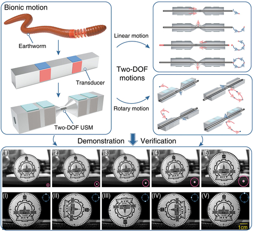
Multi-motor configuration of multi-DOF (degree of freedom) optical system is a major source of redundant structure, putting a limitation on the simple and miniaturized design. Thus, a novel two-DOF ultrasonic motor (USM) is proposed to provide a feasible method of application in the lens autofocus of the optical system. The proposed USM operates by one longitudinal mode and two orthogonal bending modes, which is inspired by the bionic motion principle of the earthworms. The frequency degeneration among the three working modes is performed, and the working principle of the USM is verified via the FEM simulation. A prototype of the two-DOF USM is fabricated, and its mechanical output characteristics are tested. The experimental results indicate that the prototype achieves the maximum rotary and linear speeds of 3319.6 rpm and 57.6 mm/s, respectively. Furthermore, we demonstrate the result of a simple focusing experiment using the prototype and obtain a series of clear pictures, which verifies the feasibility of application in the optical focusing system.
Graphical Abstract
Introduction
At present, optical focusing can significantly improve the imaging performance, and various motors have been utilized to design lens modules accordingly. For instance, as the magnetic field could vary with the position change of the lens module, Chien et al. proposed a voice coil motor (VCM) to apply in the optical lens module, which realized stable operation [Citation1]. However, as an electromagnetic motor, the VCM is susceptible to external magnetic field. Besides, functional materials are widely used in the manufacturing of actuators due to their individual characteristics. For example, Jin and Ren developed a movable lens module driven by the dielectric elastomer actuator (DEA) [Citation2]. However, the DEA has a slow response and needs high driving voltage, which is not suitable for most cameras. Moreover, thermally activated shape memory alloy (SMA) has attracted wide attention because of its shape memory effect and large output force. Hasan and Kim et al. proposed tunable lens devices based on the three SMA actuators, and a series of clear pictures could be obtained by controlling the length of springs connecting to the SMA actuator [Citation3]. However, the SMA exhibits serious nonlinear hysteresis effects.
The emerging development of piezoelectric actuators (PEAs) increasingly promotes the rapid growth of the commercial motor market and has received substantial interest from both industry and academia [Citation4–9]. The PEAs have excellent merits such as no electromagnetic interference, fast responsiveness, and self-lock when power-off and are widely used in manufacturing [Citation10,Citation11], adaptive optics instruments [Citation12,Citation13], medical auxiliary equipment [Citation14], and robots [Citation15–19]. Generally, PEAs can be classified as the resonant and non-resonant type from the viewpoint of their vibration states [Citation20]. The non-resonant-type PEAs have been applied in the autofocus modules for improving their localization ability by researchers. Based on the smooth impact drive mechanism, Jonghyun et al. developed an autofocus module with a dual-slider and achieved linear speed of 5 mm/s [Citation21]. However, the non-resonant-type PEAs with low speed cannot be applied in high-speed cameras that need to record most frames during a short operating time [Citation22]. By contrast, the resonant type PEAs have the advantages of high speed and large travel range. Therefore, the resonant-type PEAs are one of the suitable candidates to solve the above problems.
The resonant-type PEAs are usually named as the ultrasonic motors (USMs) as their working frequency is beyond 20 kHz. Generally, USMs are mainly classified into three types according to the working principles: the traveling wave motor (TWM) [Citation23,Citation24], the standing wave motor (SWM) [Citation25–27], and the hybrid modes motor (HMM) [Citation28–31]. As the pioneer in the field of professional electronic photography, Canon, Inc., integrated the TWM in the single-lens reflex camera in the 1980s [Citation32]. The torque and speed were 160 mN·m and 60 r/min, respectively; the response time was less than 1 ms. However, the complicated structure and signals are unsuitable for further miniaturization. By contrast, the SWM has the merits of simple configuration and control circuits. But the SWM is not suitable for applications that require bidirectional motions. In comparison with the TWM and SWM, the most remarkable characteristic of HMM is that the multi-DOF actuation can be achieved by adopting the desired vibration modes. To take advantage of HMMs, Canon, Co., Ltd., proposed a rod-shaped HMM and with dimensions of Φ10 mm×25 mm [Citation33]. In this study, two orthogonal first-order bending vibration modes were excited by the Langevin-type configuration. To adjust the position of lens module, the rotary motion of rotary HMMs needs to be converted into the linear motion. Thus, the autofocus module was processed with internal threads and moved back and forth accordingly. In 2005, New Scale Technologies, Co., Ltd., reported a tiny HMM with the screw transmission mechanism, which is named as the SQUIGGLE motor with the size of 1.8 mm × 8 mm × 0.6 mm. The SQUIGGLE motor transformed the rotary motion of the rod into the linear one, which was applied in the autofocus module successfully [Citation34]. Compared with Langevin-type configuration, the bonded-type PEAs are more suitable for miniaturization owing to their simple structures [Citation35,Citation36]. For instance, Mashimo et al. proposed a millimeter-scale two-DOF HMM, which successfully realized the focus of the image through the linear motion [Citation37,Citation38]. However, the application of rotary motion in the optical field has not been reported.
Generally speaking, focusing a large size of object is conducted by moving either the optical device or the object along the optical axis. In some cases, when a series of clear pictures of the partial object are captured, it may not be completed in the visual range of the objective lens due to the large size of the object. Thus, it is important to obtain clear and complete pictures of the object simultaneously. An effective strategy is to obtain clear pictures of large object via the linear motion, and the complete information of object is obtained through the rotary motion. Therefore, the position adjustment of the object and the expanded visual range of the objective lens can be realized by the linear motion and the rotary motion of the motor, respectively. The preliminary application aforementioned based on the multi-DOF USM has been rarely reported. The multi-DOF USM based on the Langevin-type configuration has the merits of large thrust force and high speed [Citation39], but the compact and simple structure is achieved by the bonded-type one. Thus, it is meaningful to realize the integral design of the multi-DOF USM based on the bonded-type configuration.
The aim of this study is to provide a feasible method of application in the lens autofocus of the optical system. Additionally, imitating the biological organisms in actuation systems to design the piezoelectric actuator is important for the fabrication of biomimetic USM [Citation15,Citation16]. Thus, the two-DOF motions of USM are inspired by the bionic motion principles of the earthworms. This work is organized as follows. The configuration and operating principle of the BT (Bonded-type transducer) are determined and discussed in Section II. In Section III, the relevant FEM study is investigated mainly. The experimental results are presented in Section IV. Finally, the conclusions are stated in Section V.
2. Configuration and working principle of two-DOF bonded-type transducer
2.1. Structure design of two-DOF bonded-type transducer
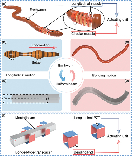
Both earthworms (Lumbricus terrestris) and inchworms are multi-segmented creatures in nature, but the locomotion mechanism of earthworms is different from that of inchworms, and the retrograde peristaltic gaits are presented while the longitudinal and circular muscles serves as the actuating unit of the hydrostatic skeleton [Citation40], as shown in )). The somites of earthworms are contracted and expanded through the circular and longitudinal muscles. The soft setae are extended and serves as anchors fixed on the ground regularly, as shown in )). Therefore, the thrust force is provided by the fixed somite to push other parts moving forward. In fact, as shown in )) and )), the peristaltic motion of earthworms is coupled by longitudinal and bending motions, which can be achieved via the longitudinal and circular muscles, respectively. Similarly, the BT can achieve the coupled motion bioinspired by the earthworms through the FEA simulation, which also includes the longitudinal and bending vibration components of the uniform beam, as shown in )) and )), respectively. Furthermore, the PZT plates could be regarded as the actuating unit. The coupled motion of BT is the elliptical trajectory or the oblique line formed on the end of the BT to push the mover or rotor, as shown in )). Therefore, the linear or rotary motion can be generated through the BT since the bending motion is used to overcome the preload exerted by the mover, while the pushing motion is caused by the longitudinal motion through the friction effect.
Figure 1. The locomotion mechanism of the earthworm and bonded-type transducer (BT). (a) The longitudinal and circular muscles of earthworm. (b) and (d) The longitudinal motion of the earthworm and BT, respectively. (c) and (e) The bending motion of the earthworm and BT, respectively. (f) The longitudinal and bending PZT plates of BT.
The inferior mechanical performance caused by inconsistent vibration characteristics of multi-feet configuration and the extra usage cost caused by multi-feet BT. Aimed at the current deficiencies in design of multi-feet BT, the single-foot driving system is designed for the developed of two-DOF BT in this study. Furthermore, the driving foot is arranged at the intermediate wave crest of bending mode for efficient actuation. Generally speaking, it is difficult to tune the resonant frequency of the first bending and longitudinal vibration modes to be close since the speed of sound for longitudinal vibration is larger than that for bending one [Citation41]. Therefore, several studies were performed to investigate the design philosophy of BT [Citation42–44]. Traditionally, the odd-order bending modes and even-order longitudinal modes are adopted simultaneously due to their adjacent wave nodes and closed resonant frequencies, or vice versa. In this study, the odd-order bending modes are considered as the tentative working modes according to the distribution of the wave crest of the uniform beam. The driving foot can be arranged at the intermediate wave crest of the uniform beam reasonably under free-free condition. The second-order longitudinal vibration mode (named as L2X mode) of BT is selected due to its large amplitude compared to high-order ones. Namely, the longitudinal–bending (L-B) modes of BT are adopted to generate the linear motion along the length of BT. The adoption of the L-B modes can achieve miniaturization of the USM compared with the longitudinal–longitudinal (L-L) modes [Citation30]. Furthermore, the rotary motion can be achieved via the two orthogonal bending (B-B) vibration modes, and frequency degeneration can be taken away due to the symmetrical section of BT. Therefore, the L2X mode and two orthogonal bending vibration modes are selected as the tentative working modes in this study. The order of bending vibration is determined through the FEM method, and then the results are obtained subsequently.
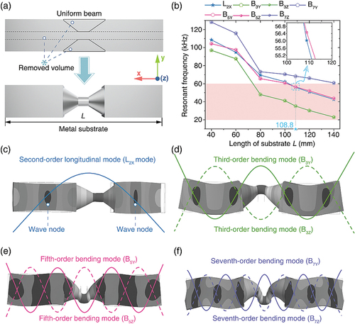
The design flow chart of proposed two-DOF USM are shown in . First, the cone-shaped horn is utilized to amplify the vibration amplitudes of BT effectively, as shown in )). For the beam-type BT, the length of the beam is determined first; the resonant frequencies of USMs range from 20 kHz to 60 kHz in most studies [Citation28–30]. Subsequently, the relationships between the resonant frequencies of the tentative working modes and the length of the metal substrate L are as shown in )). The L2X mode and the odd-order bending modes of the substrate are plotted in )), )), )) and )). Furthermore, it can be seen that the resonant frequencies of B3Y and B3Z modes are within the range of human hearing when the L exceeds 140 mm. Therefore, the L determined ranges from 100 to 140 mm in this study. Additionally, the seventh-order bending modes (named as B7Y/B7Z mode) are not considered due to their inferior vibration characteristics such as the low-amplitude. However, the resonant frequency of the L2X mode is close to the one of the fifth-order bending modes (named as B5Y /B5Z mode) by comparison with the other vibration modes. Especially, when the L is 108.8 mm, the resonant frequencies of L2X, B5Y, and B5Z mode are 56.031, 56.462, and 56.481 kHz, respectively, namely, the L2X and the B5 modes can be excited simultaneously through the same exciting frequency. Therefore, the L2X mode and B5Y /B5Z modes are chosen as the desired working modes when the three modes have approximated resonant frequencies in this study.
Figure 2. The design flow chart of two-DOF USM.
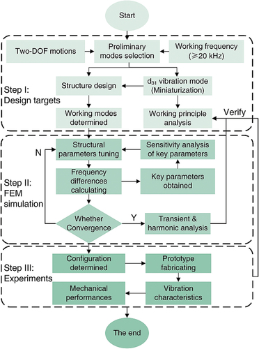
Figure 3. The metal substrate and the tentative working modes. (a) The structure of the cone-shaped horn substrate. (b) Adjustment of the resonant frequencies for the L2X and bending modes through changing the length of the metal substrate. (c) The second-order longitudinal mode. (d) Two orthogonal third-order modes. (e) Fifth-order and (f) seventh-order bending modes, respectively.
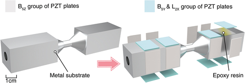
The three-dimensional model of the BT is shown in . In order to improve the mechanical performance of the USM, 16 PZT plates are placed in the wave loop of B5Y /B5Z mode. Furthermore, these PZT plates are divided into two groups (the B5Z and B5Y/L2X groups) equally and bonded on the substrate via the conductive epoxy resin. Therefore, the L2X mode, B5Y mode, and B5Z mode are excited individually by the L2X /B5Y and the B5Z group of PZT plates, respectively.
Figure 4. Configurations of the developed two-DOF BT.
2.2 Working principle of two-DOF USM
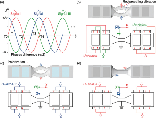
The electrical connections and polarization configurations of the PZT plates are presented in . The PZT plates are polarized along their thickness directions, which are indicated by red arrows. See )), the three voltage signals with the phase difference of π/2 are named as Signal I, Signal II, and Signal III, respectively. The BT can produce continuous self-reciprocating vibration when the PZT plates are excited with these voltage signals. As shown in )), the B5Y mode can be excited when the PZT plates are excited with Signal I and Signal III with the phase difference of , and reciprocating vibration of BT could be achieved, which is consistent with the B5Y mode plotted in )). Similarly, the B5Z mode can be excited while the B5Z group PZT plates are excited with the Signal II. Under the uniform electric field, the 4 PZT plates are elongated in thickness direction and the remaining ones are shortened regularly. Theoretically speaking, the B5Z group PZT plates can be utilized to produce the L2X mode, but the vibration is undesirable in this study. The L2X mode can be utilized to produce the axial vibration components when the Signal I is applied to the L2X group PZT plates, as shown in )). Therefore, the B5Y and B5Z modes are employed to generate the rotary motion around the X-axis when two orthogonal bending vibration modes are excited, and the linear motion along the X-axis can be obtained when the B5Z and L2X mode are excited simultaneously.
Figure 5. Schematic of exciting signals and desired working modes. (a) The exciting signals for two-DOF driving. (b) The electrical wiring diagram of B5Y mode, (c) B5Z mode, and (d) L2X mode.
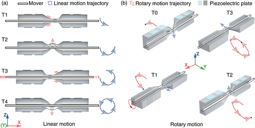
The working principle of two-DOF USM is similar to our previous study [Citation39]. Furthermore, several slim poles are utilized to serve as the mover, and the rotary speed can be protruded. When the electrodes are applied with the desired signals, the three desired working modes aforementioned are excited and the rotary and linear motions of the mover can be obtained individually, as shown in )) and )). Thus, the continuous rotary and linear motions are performed by the stator. Finally, the counter-direction motions of two-DOF BT can be achieved by adjusting the exciting signals flexibly.
Figure 6. Schematic illustration of the working principle of two-DOF USM. (a) The linear motion of the proposed motor in one period. (b)The rotary motion of the proposed motor in one period.
3. FEM simulation of two-DOF bonded-type transducer
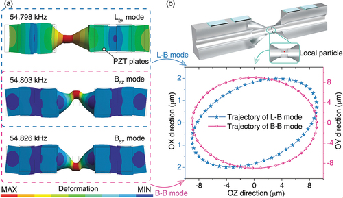
The decisive dimensions of the metal substrate are determined; thus, the resonant frequency of the L2X mode is close to that of the bending one. To minimize the difference among the resonant frequencies of the working modes, the frequency degeneration among the three working modes is carried out by FEM simulation with ANSYS software. The decisive dimensions of the metal substrate have been determined in Section 2.1. First, the material of the PZT plate is PZT-4 (Model: Hong sheng Co., Ltd, Baoding, China), and its density is 7500 kg/m3, and the total size of PZT-4 is 18 mm × 12 mm × 0.5 mm. The aluminum alloy (2A12) is selected as the material for the metal substrate (mass density: 2700 kg/m3, Young’s modulus: 7.2 × 10¹⁰ Pa, Poisson’s ratio: 0.3). It is worth noting that the conductive epoxy resin is depicted in , but it is not considered in the model settling since it is really thin and can be ignored. Moreover, the SOLID 226 and SOLID 186 elements are selected for the PZT plates and metal substrate, respectively. The desired working modes of the BT under free-free boundary conditions and their resonant frequencies are obtained by adjusting the structural parameters. The structural parameters of the stepped holes are the most sensitive parameters to the resonant frequency, namely the length and the diameter of the stepped holes hold the greatest influence on the resonant frequency, while the length of BT has been determined in Section 2. The three working modes are obtained by adjusting the parameters of stepped holes. The variation trend of the length of the stepped hole with the resonant frequencies of three working modes are plotted in )) to )), respectively. Furthermore, in order to study the change trend of stepped holes intuitively, the relationships between the diameter and resonant frequency are plotted in )), and the decisive values are marked with blue stars on the coordinate axes. Finally, the tentative dimensions of the BT are confirmed and plotted in )), and the resonant frequencies of the B5Z mode, B5Y mode, and the L2X mode are 54.798 kHz, 54.803 kHz, and 54.826 kHz, respectively, as shown in )). The maximum difference among the resonant frequencies is 28 Hz and satisfies the design of multi-mode USM. The vibration characteristic of the local particle on the driving surface is obtained via transient analysis. In the simulation part, the damping ratio is set to 0.003. The voltage and excitation frequency applied in the simulation are 100 Vp-p and 54.80 kHz, respectively, and the related results as shown in )). The vibration amplitudes in the OZ and OY direction are more significant than that in the OX direction; the maximum amplitude of the former is 9.01 μm, while the latter is 1.98 μm. The PZT plates are arranged at the position more biased toward the wave loop of bending modes to degenerate the frequencies of desired working modes, which may be the reason that the lower amplitude is achieved by the longitudinal mode. Moreover, compared to the d31 operating mode, the large amplitudes of longitudinal mode are achieved by the d33 operating mode [Citation39]. The trajectory in blue and pink color represents the results of the L-B and B-B modes in the steady-state, respectively, as shown in )). The longitudinal mode and bending one are two different vibrations with diverse properties for a uniform beam. The two elliptical trajectories are not the same due to the different phase lag of the longitudinal displacement response and the bending mode one. Therefore, the two-DOF motions can be achieved, which are illustrated in the next section.
Figure 7. Influences of main geometric parameters of BT on B-B frequency. (a) Geometric dimensions of BT. (b) B-B frequency under different h2. (c) Resonant frequency under different d1, d2, and d3, where the decisive values are marked with light blue stars. (d) Resonant frequency under different h1.
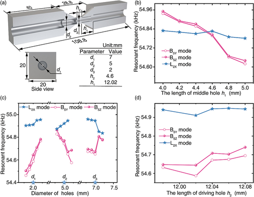
Figure 8. FEM results of the proposed two-DOF BT. (a) Three desired working modes. (b) The transient analysis results of motion trajectories of the driving surface (at steady state).
4. Experimental characterization
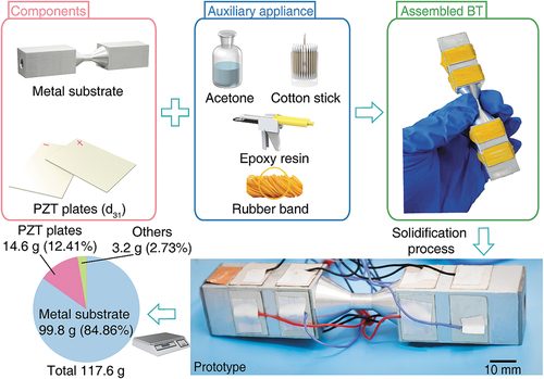
To verify the design and working principle of BT, a prototype was fabricated according to the design results listed in )). The two-DOF BT was fabricated and assembled in simple and scalable steps as shown in . The metal substrate and PZT plates are cleaned with acetone first to cleaning up. Subsequently, the conductive epoxy resin (Model: Hysol E-120HP, LOCTITE, USA) and rubber band are utilized to bond and fasten the PZT plates to the metal substrate, respectively. Afterward, the assembled BT solidified at room for 48 hours; thus, the PZT plates are fixed in the metal substrate completely. The BT is soldered at 250°C, which is lower than the Curie temperature of the PZT plates. Finally, the total weight of the prototype is 117.6 g. The dynamic characteristics of the BT are tested through the experimental method, and then a series of experiments of mechanical performances are obtained in sequence.
Figure 9. Fabrication, assembling process and weight distribution of fully assembled BT.
4.1. Vibration characteristics tests of the BT
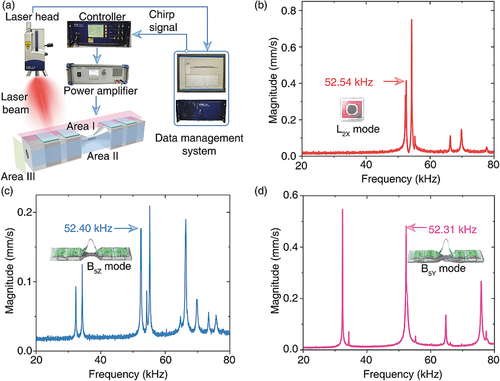
Vibration characteristic tests were carried out using a Doppler laser vibrometer (Model: PSV-400-M2, Polytec, Germany). In the experiment, three spatial planes perpendicular to the vibration direction are selected as frequency sweep areas, which are named as Area I, Area II, and Area III, respectively. The sweep range and voltage of the chirp signal are set to 20 kHz to 80 kHz and 10 Vp-p, respectively, as shown in )). The characteristics of normalized magnitude verse frequency are extracted and plotted in )) to )), respectively. It can be seen that the resonant frequencies of L2X, B5Z, and B5Y modes are 52.54 kHz, 52.31 kHz, and 52.40 kHz, respectively. Furthermore, the slight difference is caused by the discrepancies in materials and assembly errors, which is acceptable within a reasonable range for operating.
Figure 10. Testing results of vibration characteristics. (a) Schematic diagram of vibration test of the BT. (b) Vibration characteristics of the L2X mode. (c) Vibration characteristics of the B5Z mode. (d) Vibration characteristics of the B5Y mode.
4.2. Output characteristic experiments
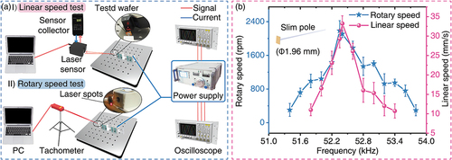
The two-DOF motions are realized by tuning the frequency and excitation voltage of the three AC signals. To experimentally investigate the mechanical performance of the two-DOF USM, the mechanical experimental system is established to verify the optimal frequencies of linear and rotary speeds, as shown in )). In order to demonstrate the experimental setups of two-DOF motions intuitively, the blue and the purple line are used to represent the flow direction of current and signal among the equipment, respectively. A power supply (Model: QD-8D, China) utilized to produce the three voltage signals are plotted in )). The linear and rotary speeds of the mover were tested by the laser displacement sensor (Model: LKH020, KEYENCE, Japan) and the tachometer (Model: UT371, UNI-T, China). The slim poles are selected as the mover, and an ultrathin wafer is bonded to the end of the mover to increase the testing area. The relationships of output speeds and excitation frequency are plotted in )). Under the voltage of 100 Vp-p and on-load conditions, the maximum linear and rotary speeds are 33.21 mm/s and 2184.95 rpm at 52.40 kHz and 52.35 kHz, respectively. In this study, there are small discrepancies in resonant frequencies of three working modes due to the assembling and manufacture error. The optimal frequencies of linear and rotary motions are 52.40 kHz and the 52.35 kHz, respectively, which are consistent with the vibration test results. Therefore, there are two excitation frequencies for rotary and linear motion, respectively.
Figure 11. Experimental setup and results for USM’s speed measurement. (a) Experimental setup for two-DOF speed tests. (b) Frequency sensitivity results for the rotary and linear speeds of the mover.
Two frequencies are chosen as the optimal excitation frequency for a series of experiments subsequently. Furthermore, the optimal frequencies of linear and rotary motions are consistent with the testing results in . Therefore, both L-B modes and B-B modes are successfully excited and verified.
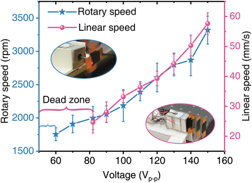
The slim poles made of stainless steel (SUS304) are applied to the speed and carrying load tests, respectively. First, the output speeds of the mover under no-load conditions are tested, and the results are plotted in . It can be observed that the starting voltages for rotary and linear motions are 60 Vp-p and 82 Vp-p, respectively. In , the amplitudes of longitudinal and bending modes are 1.98 μm and 9.01 μm, respectively. The simulation result indicates that the longitudinal mode achieves lower amplitude under the same excitations. Thus, the slim pole cannot overcome the friction between the driving face, and the slim pole until sufficient voltage is applied. Moreover, there is a clearance fit between the driving face and the slim poles. In the experimental part, the rotary and linear motions of prototype are observed when the 60 Vp-p and 82 Vp-p are applied to the PZT plates, respectively. Furthermore, it can be seen from the curve that the speeds increase with the increment of voltage amplitude. The maximum output speeds for rotary and linear motions are 3319.6 rpm and 57.6 mm/s under the voltage of 150 Vp-p, respectively.
Figure 12. Relationships between the rotary and linear speeds and the voltage under no-load conditions.
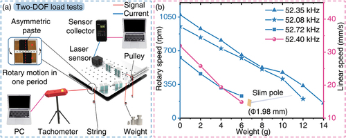
In order to investigate the load capacity of the two-DOF USM, the external load tests were carried out by varying the weight. The experimental setup for the load capacity tests is shown in )). The slim pole with diameters of 1.98 mm is applied to increase the friction between the driving surface and the mover, and the black adhesive tape is pasted on the wafer asymmetrically. Furthermore, a string-pulley system was established for linear actuation tests. As shown in )), the mover could rotate when the excitation frequency varies from 52.08 kHz to 52.72 kHz, which are close to the optimal frequency of rotary motion. Thus, the three frequencies are selected as the exciting frequencies in the experiment, and the output speeds decreases with the increase of the external load. Compared to the fifth-order bending modes, the vibration amplitude of the L2X mode is smaller in this work. Therefore, the mover could drive along the X direction with the external load at its optimal frequency. The testing results show that the maximum load and torque are 6 g and 0.14 mN·m, and the speeds are 14.875 mm/s and 155.6 rpm under the voltage of 100 Vp-p in linear and rotary motions, respectively. These results show that the proposed USM can withstand light loads, and the related demonstration will be discussed in the next section.
Figure 13. Experimental setup and results for USM’s load/torque measurement. (a) Experimental setups for two-DOF load tests. (b) Two-DOF speeds of prototype under different weights.
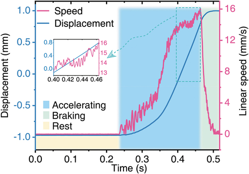
In order to investigate the influence of preload on the transient characteristics, the transient responses of the linear speed under no-load conditions were carried out, as shown in . The green (from starting to 0.027s) and pink areas (from 0.027s to 0.463s) represent the states of power-on and power-off of the USM, respectively. The rising curve exhibits the delay characteristic since the time constant is mainly determined by the friction force between the slim pole and the driving face. Compared with the electromagnetic motor, the USM has an obvious drooping characteristic. During the braking interval, the power was turned off at 0.463 s and the speed began to decrease rapidly, which shows the negative acceleration due to the friction force. Due to the limited measuring range of the laser sensor, the acceleration interval of the mover existed for a short time. The phenomenon shows that the USM has not reached a stable working interval of operation.
Figure 14. Transient response characteristics of linear motion.
Recent studies of multi-DOF USMs are compared and summarized in . The similar configuration proposed by Liu et al. achieves a high linear speed of 573 mm/s and 543 mm/s and a thrust force of 24 N and 22 N in two directions [Citation39]. However, its total volume was larger due to the Langevin-type configuration adopted. Similarly, 16 PZT plates were utilized in the three-DOF USM developed to improve the rotary speed, but its rotary speed is at the middle level [Citation45]. A tiny USM was proposed by Mashimo et al. [Citation37], but the rotary speed in this work is more prominent. In this work, we achieved significant rotary speed through 16 PZT plates and slim pole, and the bonded-type feature is conductive to realize further miniaturization of USM.
Table 1. Comparison of multi-DOF ultrasonic motors in recent years.
The high displacement resolution of USM could be obtained when the sinusoidal burst mode is applied [Citation15,Citation39]. In this study, the linear step displacement of mover is studied when the pulse signal is employed. The pulse repetition frequency is set as 50 Hz, while the duty factor varies from 5% to 50%, which could be utilized to control the step displacement. The starting points of the curves are set to the end point of measurement range to be observed and contrasted intuitively. As shown in , the linear step displacement achieved by prototype varies to the duty factor while the starting voltage is applied. The minimum step displacement of 1.2 µm is obtained when the duty factor turned to 5%. Namely, the step displacement could be controlled by adjusting the duty factor successfully. The burst mode cannot only control the displacement of USM but also bring a high resolution of displacement conveniently.
5. Demonstration of two-DOF motions
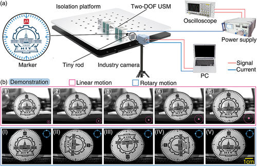
To verify the effectiveness of the two-DOF motions, a simple focusing operation and posture adjustment system were established to obtain the detail information from the clear pictures. )) shows the experimental system and the pictures captured by an industrial camera (MER-031-860U3M, Daheng Imaging) with a frame rate of 860 FPS (frames per second). Moreover, the special design is adopted and regarded as a marker, which is bonded to the end of the tiny rod. First, the distance between the marker and the industrial camera are adjusted through the linear motion, until the picture of marker is clear, as shown by (1)–(5) in )) and the posture of the marker aligned by the rotary motion, as shown by (I)–(V) in )). Finally, the clear picture of marker was obtained, and its posture could be aligned through rotary motion. Here, the rotary motion of the two-DOF USM can be utilized to obtain more detailed information and expand the visual range of objective lens in a rough optical focusing device.
Figure 15. Relationships between the step displacements and the duty factor.
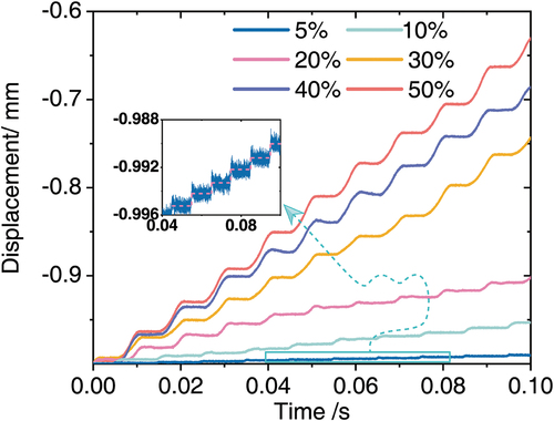
Figure 16. Demonstration of two-DOF motions. (a) Experimental setup for two-DOF motion tests. (b) The demonstration of two-DOF motions.
6. Conclusion
In this work, a two-DOF USM based on the bonded-type transducer combining the longitudinal-bending (L-B) and orthogonal bending (B-B) modes was proposed and designed. The proposed two-DOF USM was composed of 16 PZT plates and one metal substrate. The working principle of the USM was analyzed and verified by the FEM simulation. A prototype of USM was fabricated, and related mechanical characteristics were tested. The resonant frequencies of L2X, B5Z, and B5Y modes were 52.54 kHz, 52.31 kHz, and 52.40 kHz, respectively. The experimental results showed that the maximum linear and rotary speeds of mover were 57.6 mm/s and 3319.6 rpm under the voltage of 150 Vp-p, respectively. The mechanical load were 0.06 N and 0.14 mN·m when the linear and rotary speeds were 52.72 mm/s and 155.6 rpm, respectively. Moreover, the linear step displacement was 1.2 µm, while the duty factor and the pulse repetition frequency were set to 5% and 50 Hz, respectively. Therefore, the working principle and feasibility of the design were verified by means of the FEM simulation and experimental results. Moreover, a simple focusing operation and posture adjustment system were established to demonstrate the preliminary application of optical focusing. The linear motion was utilized to adjust the position of the object, while the rotary one was adopted to expand the visual range of the objective lens in optical focusing system. In future work, the study related to the two-DOF USM will be focused on the integration of the focal length adjustment and aperture control functions.
Supplemental Material
Download MP4 Video (60.1 MB)Acknowledgments
This work was supported by the National Natural Science Foundation of China, the China Postdoctoral Science Foundation, and the Postdoctoral Science Foundation of Heilongjiang Province.
Disclosure statement
No potential conflict of interest was reported by the author(s).
Supplementary material
Supplemental data for this article can be accessed online at https://doi.org/10.1080/19475411.2022.2084173
Additional information
Funding
Related Research Data
References
- Liu C, Lin PD. A miniaturized low-power VCM actuator for auto-focusing applications. Opt Express. 2008;16:2533–2540.
- Jin B, Ren H. Position-movable lens driven by dielectric elastomer actuator. Opt Eng. 2021;55:1–7.
- Hasan N, Kim H, Mastrangelo CH. Large aperture tunable-focus liquid lens using shape memory alloy spring. Opt Express. 2016;24:13334.
- Tian X, Liu Y, Deng J, et al. Single-phase drive bending-bending piezoelectric actuator operated under 8-shaped trajectory vibration: concept, computation and experiment evaluation. Mech Syst Signal Process. 2020;139:106637.
- Zhang S, Liu Y, Gao X, et al. Development of a cross-scale 2-DOF piezoelectric rotary platform based on active friction switching. Int J Mech Sci. 2022;220:107165.
- Gao X, Deng J, Zhang S, et al. A compact 2-DOF micro/nano manipulator using single miniature piezoelectric tube actuator. IEEE Trans Ind Electron. 2022;69:3928–3937.
- Zhang S, Liu Y, Deng J, et al. Development of a two-DOF inertial rotary motor using a piezoelectric actuator constructed on four bimorphs. Mech Syst Signal Process. 2021;149:107213.
- Li X, Yao Z, Li R, et al. Dynamics modeling and control of a V-shaped ultrasonic motor with two Langevin-type transducers. Smart Mater Struct. 2020;29. DOI:10.1088/1361-665X/ab627a.
- Sanguinetti B, Varcoe BTH. Use of a piezoelectric SQUIGGLE® motor for positioning at 6 K in a cryostat. Cryogenics (Guildf). 2006;46:694–696.
- Jerez-Mesa R, Travieso-Rodriguez JA, Gomez-Gras G, et al. Development, characterization and test of an ultrasonic vibration-assisted ball burnishing tool. J Mater Process Technol. 2018;257:203–212.
- Huang H, Zhao H. Non-ideal assembly of the driving unit affecting shape of load-displacement curves. Meas. Sci and Tech. 2015:035601. 10.1088/0957-0233/26/3/035601.
- Zhang S, Liu Y, Deng J, et al. Development of a low capacitance two-axis piezoelectric tilting mirror used for optical assisted micromanipulation. Mech Syst Signal Process. 2021; 154: 107602.
- Taylor RM, Robinett W, Chi VL, et al. The nanomanipulator: a virtual-reality interface for a scanning tunneling microscope. Proc 20th Annu Conf Comput Graph Interact Tech SIGGRAPH 1993 Anaheim, CA, USA. 1993;127–134.
- Deng J, Liu S, Liu Y, et al. A 2-DOF needle insertion device using inertial piezoelectric actuator. IEEE Trans Ind Electron. 2022;69:3918–3927.
- Liu Y, Li J, Deng J, et al. Arthropod‐metamerism‐inspired resonant piezoelectric millirobot. Adv Intell Syst. 2021;3:2100015.
- Zhu P, Peng H, Lu X, et al. A steerable miniature legged robot based on piezoelectric bending actuators. Smart Mater Struct. 2020;29. 10.1088/1361-665X/ab74bb.
- Deng J, Liu Y, Zhang S, et al. Development of a nanopositioning platform with large travel range based on bionic quadruped piezoelectric actuator. IEEE/ASME Trans Mechatronics. 2021; 26: 2059–2070.
- Ma X, Liu Y, Liu J, et al. Crabbot: a pole-cimbing robot driven by piezoelectric stack IEEE Trans Robot. 2021;38:765–778.
- Wang L, Jin J, Zhang H, et al. Theoretical analysis and experimental investigation on a novel self-moving linear piezoelectric stepping actuator. Mech Syst Signal Process. 2020;135:106183.
- Tian X, Liu Y, Deng J, et al. A review on piezoelectric ultrasonic motors for the past decade: classification, operating principle, performance, and future work perspectives. Sens Actuators A Phys. 2020;306:111971.
- Lee J, Kwon WS, Kim KS, et al. A novel smooth impact drive mechanism actuation method with dual-slider for a compact zoom lens system. Rev Sci Instrum. 2011;82:1–8.
- Pueo B. High speed cameras for motion analysis in sports science. J Hum Sport Exerc. 2016;11:53–73.
- Zhou Y, Chang J, Liao X, et al. Ring-shaped traveling wave ultrasonic motor for high-output power density with suspension stator. Ultrasonics. 2020;102:106040.
- Frangi A, Corigliano A, Binci M, et al. Finite element modelling of a rotating piezoelectric ultrasonic motor. Ultrasonics. 2005;43:747–755.
- Lu D, Lin Q, Chen B, et al. A single-modal linear ultrasonic motor based on multi vibration modes of PZT ceramics. Ultrasonics. 2020;107:106158.
- Ma Y, Choi M, Uchino K. Single-phase driven ultrasonic motor using two orthogonal bending modes of sandwiching piezo-ceramic plates. Rev Sci Instrum. 2016;87(11):115004.
- Li J, Deng J, Liu Y, et al. A linear piezoelectric actuator based on working principle of three-petal mouth of a rabbit. IEEE Trans Ind Electron. 2022;69:5091–5099.
- Yi Y, Seemann W, Gausmann R, et al. A method for matching the eigenfrequencies of longitudinal and torsional vibrations in a hybrid piezoelectric motor. J Sound Vib. 2006;295:856–869.
- Liu Y, Wang L, Gu Z, et al. Development of a two-dimensional linear piezoelectric stepping platform using longitudinal-bending hybrid actuators. IEEE Trans Ind Electron. 2018;66:3030–3040.
- Asumi K, Fukunaga R, Fujimura T, et al. Miniaturization of a V-shape transducer ultrasonic motor. Jpn J Appl Phys. 2009;48:42–47.
- Yun CH, Ishii T, Nakamura K, et al. A high power ultrasonic linear motor using a longitudinal and bending hybrid bolt-clamped Langevin type transducer. Japanese J Appl Physics, Part 1 Regul Pap Short Notes Rev Pap. 2001;40:3773–3776.
- Maeno T. Recent progress of ultrasonic motors in Japan Proc.First Int.Workshop Ultrason.Motors Actuators 2005 Yokohama, Japan. 2005;15–18.
- Maeno T, Okumura I. How to make high-efficiency ultrasonic motors. 2004;409–412.
- a HD. Simple ceramic motor … inspiring smaller products. Actuator 2006, 10th Int Conf New Actuators. Bremen, Germany. 2006;14–16.
- Zhang A, Wang L, Jin J, et al. A novel piezoelectric actuated 2-DOF joint for underwater manipulator: design, simulation, and experimental investigation. Smart Mater Struct. 2021;30:105032.
- Li H, Deng J, Zhang S, et al. Design and experiment of a three-feet linear ultrasonic motor using third bending hybrid modes. Sens Actuators A Phys. 2021;331:112990.
- Mashimo T, Toyama S. Rotary-linear piezoelectric actuator using a single stator. IEEE Trans Ultrason Ferroelectr Freq Control. 2009;56:114–120.
- Izuhara S, Mashimo T. Design and characterization of a thin linear ultrasonic motor for miniature focus systems. Sens Actuators A Phys. 2021;329:112797.
- Liu Y, Yan J, Wang L, et al. A two-DOF ultrasonic motor using a longitudinal-bending hybrid sandwich transducer. IEEE Trans Ind Electron. 2019;66:3041–3050.
- Tang Z, Lu J, Wang Z, et al. Development of a new multi-cavity pneumatic-driven earthworm-like soft robot. Robotica. 2020;38:2290–2304.
- Nguyen T, Frail C. . Utrasonic Transducers:Materials and Design for Sensors, Actuators and Medical Applications. Cambridge: Woodhead Publishing. 2012; ISBN 978-0-85709-630-2(online).
- Kanda T, Makino A, Oomori Y, et al. A cylindrical micro ultrasonic motor using micro-machined piezoelectric vibrator. dig tech pap -int conf solid state sensors actuators microsystems. TRANSDUCERS ’05. 2005;1. 721–724.
- Wang Y, Wang L. Design, fabricate, and experimental verification of an ultrasonic linear motor derived from V-type motors[J]. Rev Sci Instrum. 2020;91:045002 .
- Zhang H, xiang DS, yi ZS, et al. Ultrasonic micro-motor using miniature piezoelectric tube with diameter of 1.0 mm. Ultrasonics. 2006;44:603–606.
- Wang L, Quan Q, Xue K, et al. Development of a three-DOF piezoelectric actuator using a thin cross-beam vibrator. Int J Mech Sci. 2018;149:54–61.