
 ?Mathematical formulae have been encoded as MathML and are displayed in this HTML version using MathJax in order to improve their display. Uncheck the box to turn MathJax off. This feature requires Javascript. Click on a formula to zoom.
ABSTRACT
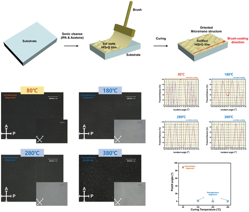
A hafnium strontium oxide (HfSrO) liquid crystal (LC) alignment film was efficiently created through brush coating, and its ability to change the LC alignment direction was confirmed. A brush was applied to HfSrO sol coated on an indium-tin oxide substrate, after which the coating was solidified at various curing temperatures. It was confirmed that a directional micro/nanostructure was formed above 280°C due to the shear stresses caused by the movement of the brush hairs. Surface chemical changes were analyzed by using X-ray photoelectron spectroscopy and contact angle measurements. As the curing temperature increased, the prevalence of oxygen bonds increased and the contact angle decreased, thereby increasing the surface energy. The anisotropic boundary of the microgrooves and the van der Waals forces due to an increase in surface energy changed the alignment direction of LC molecules from vertical to horizontal, as verified through polarized optical microscopy and pretilt angle measurements. Thus, the efficiency of the brush-coating method, which dramatically simplifies the LC alignment film process, was confirmed. The homeotropic/homogeneous LC alignment property of the HfSrO film produced through brush coating depending on the curing temperature provides an innovative approach for LC alignment.
GRAPHICAL ABSTRACt
1. Introduction
Micro/nanostructure formation through surface modification plays a key role in modern display engineering[Citation1]. Surface modification can significantly improve the performance of functional devices for biological reactions [Citation2], optics [Citation3], mechanics, and electricity, as well as control device properties for electro-optics[Citation4]. The undulating and quasi-periodic properties of the films contribute to improving the performance of solar cells [Citation5] and optical applications such as organic light-emitting diodes [Citation6] and liquid crystal (LC) displays [Citation7]. Moreover, the LC orientation must be uniform for the production of high-quality and high-resolution LC devices for the LCD industry[Citation8]. For uniform alignment of LC molecules, two key technologies are required: the surface coating of the LC layer and the alignment process.
Deposition and coating processes are required to obtain a stable LC alignment layer, and to achieve this, various deposition methods including spray pyrolysis [Citation9], chemical vapor deposition [Citation10], sputtering [Citation11], evaporation [Citation12] and solution process [Citation13] have been applied and studied. Of these, solution processing has advantages for film crystallization and orientation (important factors in functional device applications): it is easy to control, is cost-effective, and can be conducted at low temperatures. Because the sol-gel process is based on a non-vacuum system and a liquid phase process, it is relatively inexpensive compared to the equipment required for vacuum deposition. It can be applied to obtain electro-optical devices, and also has other advantages such as high homogeneity, low temperature process, etc. Current solution treatment methods include bar coating, blade coating, spin coating, dip coating, and brush coating. The latter aligns the particles in a certain direction and contributes to the formation of micro/nanostructures during the coating process.
Various alignment technologies for uniform LC alignment such as rubbing process [Citation14,Citation15], photoalignment technology [Citation16], nanoimprint lithography [Citation17], and ion beam irradiation [Citation18–20] have been developed. The rubbing process is the most commonly used method for inducing surface anisotropy and aligning LC molecules by generating microgrooves through rubbing. However, this rubbing method has disadvantages such as micro-defects on the surface and high cost due to large-area processing, and so the above various alignment technologies are being actively developed. However, the film deposition and alignment processes are separated most of the alignment technologies mentioned above. These two steps inevitably cause disadvantages such as complicated processing, the generation of contamination debris, increased process costs, and difficulties in large-scale processing.
Herein, we propose a brush-coating method as a one-step alignment technology that combines film deposition and the alignment process, which is economical and enables high throughput. In the brush-coating process, a retracting force is generated due to the movement of the brush hairs, which induces shearing stress in the alignment layer in the sol state to form oriented micro/nanostructures; these generate anisotropy on the surface and make it possible to control the surface energy.
Also, the conversion of the alignment direction of liquid crystal molecules according to the curing temperature opens the possibility as an alignment layer that can be applied more and more. The alignment direction of liquid crystal molecules greatly affects the basic driving method of LC devices. The properties of the Hf-doped SrO film, which show both the homeotropic alignment used for vertical alignment mode and the homogeneous alignment specified for in-plane switching mode and twisted nematic mode, have very high research value.[Citation21,Citation22, Citation23,Citation24]
Various analyses were conducted to uncover the surface modification and LC alignment characteristics of the HfSrO films. Surface modification was analyzed by using atomic force microscopy (AFM), X-ray photoelectron spectroscopy (XPS), and contact angle measurements. LC cells assembled with inverse antigenic structures were used to characterize the LC alignment ability of the process by using polarized light microscopy (POM), pretilt angle measurements, and thermal stability testing of brush-coated HfSrO2 films cured at 80, 180, 280, and 380°C.
2. Experimental
2.1 Material preparation
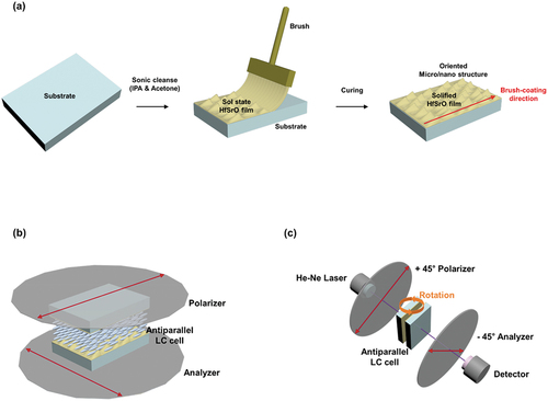
HfSrO solution was prepared via a solution process by adding 0.01 mol of hafnium(IV) chloride(>98% trace metals basis) and 0.09 mol of strontium nitrate (99.995% trace metals basis) in 2-methoxyethanol. The resulting solution was stirred at 420 rpm and 75°C for 2 h; it was then stabilized by adding a few drops of monoethanolamine and acetic acid, and the mixture was aged for 1 day. Indium tin oxide (ITO)-coated glass substrates (32 × 22 × 1.1 mm with a sheet resistance of 10 Ωsq−1; Samsung Corning 1737) were ultrasonically cleaned for 10 min each in acetone and isopropyl alcohol. Afterward, they were washed in deionized water for 10 min and dried with N2 gas. ) shows a schematic of the manufacturing process of the brush-coated HfSrO film and the LC cell. All brush coatings were made using a nylon flat brush (900A, ALPHA), so the brush material and density were uniform. In addition, the brush is fixed in the brush holder and the height is marked so that the coating can always be carried out in the same position. Since the fixed substrate then moved at the same speed under the stress of the brush, it can be seen that the brush coating speed was also uniform.
Figure 1. (a) Schematic for brush coating process, (b) Polarized optical microscopy, (c) Crystal rotate method.
2.2 Surface analyses of the HfSrO film
To determine how the brush-coating process shaped the morphology of the HfSrO film, the surface of the latter was observed by using an AFM system (XE-Bio, Park Systems); the surface height and shape were numerically analyzed through line profiling. The chemical and bonding compositions of the HfSrO film were determined with an XPS device (K-Alpha, Thermo VG). The light transmittance was measured using an ultraviolet-visible spectrophotometer (V-650, JASCO Inc.) in the wavelength range of 300–900 nm.
2.3 LC cell fabrication and LC alignment analysis
To determine the LC alignment properties, LC cells containing two nanopatterned HfSrO films, which formed antiparallel structures with a cell spacing of 60 µm, were fabricated. Positive LCs (ne = 1.595, no = 1.484, Δn = 0.111, Δε = 10.3, Tc = 81.8°C; IAN-5000XX T14, JNC Co.) were injected by applying a capillary force, and their orientation was determined with a POM system (BXP 51, Olympus). The pretilt angles were determined through the crystal rotation method (TBA 107, Autronic). A brief schematic of the POM measurement is provided in ). The LC cell to be measured is placed between two polarizers and an analyzer and transmits light. After that, the alignment direction and stability of the LC molecules can be checked depending on whether light is transmitted or not. ) provides a simplified schematic of the pretilt angle measurement. Measurements were performed with the crystal rotate method. Position the polarizer and analyzer at +45° and −45°, respectively, and rotate the LC cell between them. Then, the helium-neon laser is transmitted toward the LC cell, and the passed laser is detected. The LC cell rotates from −70° to +70°, and the transmittance according to the rotation angle is shown on the graph, and the stability of the LC orientation can be analyzed by comparing this graph with the simulation data.
3. Results and discussion
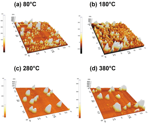
show AFM images of brush-coated HfSrO films cured at 80, 180, 280, and 380°C, respectively. It can be seen that particles were randomly distributed in the brush-coated HfSrO film cured at 80 and 180°C. As shown in ), oriented micro/nanostructures on the film surface were formed in the sol state immediately after brush coating. As the brush hairs passed through the surface, they induced a retracing force in the deposited bulk solution, which led to shear stress in the sol-state HfSrO film. After that, the sol-state film was cured on a hot plate at a high temperature. When a sufficient curing temperature was not applied, the micro/nanostructures collapsed and residual solvent was generated. Conversely, micro/nanostructures in the form of large partial grooves showing directionality were formed in the brush-coated HfSrO films cured at 280 and 380°C. This means that the morphological structure of the surface formed during the brush-coating process solidified at a high temperature and formed the microgrooves required for homogeneous LC alignment.
Figure 2. AFM images of brush-coated HfSrO film cured at (a)80°C, (b)180°C, (c)280°C, and (d)380°C.
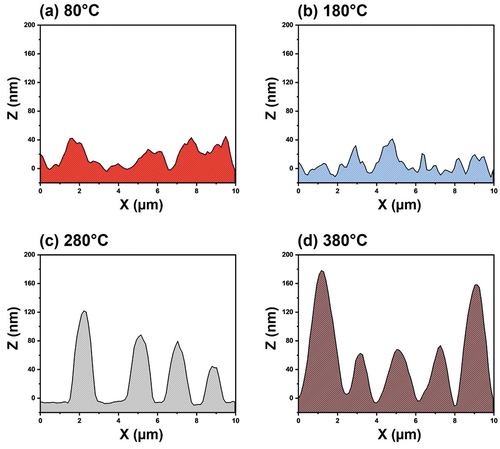
In a more specific analysis, we investigated the line profile data of brush-coated HfSrO films cured at 80–380°C, as exhibited in . In ), it can be seen that the film surface exhibited low-height and non-periodic structures. On the other hand, ) show the formation of a microgroove pattern with a certain periodic structure. The line profile data of the brush-coated HfSrO film cured at 280 and 380°C indicate an average height of around 80 and 106 nm, respectively, with a period of approximately 2 μm. The difference in the peak heights of the film surfaces according to curing temperature was further specified through surface roughness analysis (); the mean surface roughness (Ra), root-mean-squared roughness (Rq), and mean roughness depth (Rz) of the films increased with incremented curing temperature. The Ra, Rq, and Rz values of the 80 and 180°C samples did not change significantly (46.1, 71.2, and 558.1 vs. 52, 70.9, and 524.2, respectively). On the other hand, the values increased significantly in the 280 and 380°C samples (54.4, 102, and 723.9 vs. 87.7, 440.2, and 928.5), respectively. Thus, it was confirmed that a partial microgroove pattern necessary for LC homogeneous alignment was formed in the brush-coated HfSrO films at a temperature of 280°C or higher.
Table 1. Surface roughness (Ra), root-mean-squared roughness (Rq), and mean roughness depth (Rz) of brush-coated HfSrO film cured at 80°C, 180°C, 280°C, and 380°C
Figure 3. AFM line profile analysis of brush-coated HfSrO film cured at (a)80°C, (b)180°C, (c)280°C, (d)380°C.
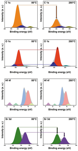
It is important not only to observe the shape change of the brush-coated film surface according to the curing temperature but also to analyze the successful deposition and chemical composition of the thin film, which was accomplished through XPS analysis. The deconvoluted core-level C 1s, O 1s, Hf 4f, and Sr 3d spectra (analogous to the constituent elements of the brush-coated HfSrO film) of the films formed at 80 and 280°C are shown in . Changes in the heights of the sub-peaks are indicated by arrows. First, in the C 1s spectrum of the 80°C film, three sub-peaks appearing at 283.9, 285.2, and 287.8 eV correspond to C-C, C-O, and C = O bonds, respectively; the peak heights were significantly reduced for the 280°C film, which is due to the residual solvent being expelled from the HfSrO film at high temperature. The decrease in the number of C-O, C = O, and C-C bonds due to the evaporation of the residual solvent was more prevalent than the increase in oxygen bonds due to oxidation at the surface. In the O 1s spectrum for the 80°C film, the sub-peak at 529.4 eV corresponds to metal-oxide bonds formed by Hf and Sr while the sub-peak at 531.4 eV corresponds to oxygen vacancies. The heights of both peaks in the O 1s spectrum of the 280°C film increased, with their centers shifting to 529.7 and 531.5 eV, respectively, thereby indicating the active thermal oxidation state of the 280°C film. In addition, the increase in the peak height and shift for the metal-oxide were larger than those for the oxygen vacancies, and the bonding ratio also increased significantly from 7.8% to 16%. Thus, the metal-oxide bonding reaction occurred more readily during the high-temperature curing of the brush-coated film. A doublet peak structure due to spin-orbit splitting (the Hf 4f7/2 sub-peak at 16.2 eV and the Hf 4 f5/2 sub-peak at 18.0 eV) was observed in the Hf 4 f spectrum for the 80°C film. However, that of the 280°C film indicates peaks shifts to 16.1 and 17.6 eV, respectively, but no significant changes in peak height. The Sr 3d spectrum of the 80°C film exhibits doublet peak structures (the Sr 3d5/2 sub-peak at 133.2 eV and the Sr 3d3/2 sub-peak at 135 eV), which had shifted to 133.4 eV and 135.1 eV and decreased in the spectrum of the 280°C film. The results of the XPS analysis confirm that the HfSrO film was properly formed through the brush-coating process by curing at 280°C, and the residual solvent had evaporated. In addition, the peak shifts due to active thermal oxidation confirm film solidification.
Figure 4. XPS spectra of brush-coated HfSrO film cured at 80°C and 280°C. The deconvoluted spectra of C 1s, O 1s, Hf 4 f, and Sr 3d are shown, respectively.
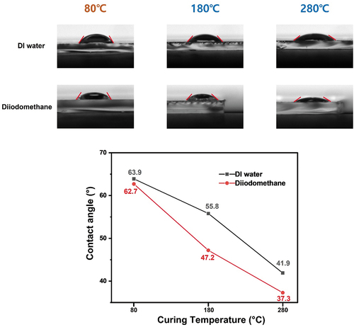
The chemical affinities of the brush-coated HfSrO films cured at 80, 180, and 280°C were analyzed by conducting contact angle measurements. In general, a high contact angle indicates hydrophobicity and a low contact angle indicates hydrophilicity. A drop of deionized (DI) water and diiodomethane were dropped on each film, and the angle formed with the surface was photographed. As can be clearly seen in , the contact angle of the brush-coated HfSrO films decreased as the curing temperature was increased. The 80°C film attained contact angles of 63.9° with DI water and 62.7° with diiodomethane, which decreased to 55.8° and 47.2°, respectively, for the 180°C film. Last, the lowest values of 41.9° and 37.3°, respectively, were recorded for the 280°C film. Through this, it was found that the brush-coated HfSrO film has more hydrophilic properties as the curing temperature increases, and the hydrophilic properties of the film contribute to the homogeneous alignment of LC molecules.
Figure 5. Contact angle measurement data of brush-coated HfSrO films cured at 80°C, 180°C and 280°C. The actual measurement picture is shown above, and the change in the contact angle value is expressed as a graph below.
The brush-coated HfSrO films cured at 80, 180, and 280°C were used in the assembly of antiparallel LC cells. Afterward, POM images of the LC cells were observed in crossed-polarizer mode (the larger images in ) by placing the polarizer parallel to the alignment direction and the analyzer perpendicular to the alignment direction and rotated crossed-polarizer mode (the inset images in where each polarizer is rotated by 45°. In , dark images for the 80°C sample LC cell can be observed in both crossed-polarizer and rotated crossed-polarizer mode. In contrast, LC cells fabricate with 180°C, 280°C and 380°C samples show dark image in crossed-polarizer mode and a white image in the rotated crossed-polarizer mode. This difference is due to the alignment direction of the LC molecules. In homeotropic alignment, where the LC molecules align perpendicular to the substrate, light is blocked regardless of the rotation of the crossed polarizers because there is no light path. However, in homogeneous alignment in which the LC molecules are aligned parallel to the substrate, a dark image is observed in crossed-polarizer mode because the light polarized along the polarizer passes through the LC molecules and is blocked by the analyzer. However, because the light passing through the molecules is not perfectly perpendicular to the analyzer, some of it passes through. Based on this, it was found that the 80°C sample showed homeotropic alignment while the 180°C, 280°C and 380°C samples showed homogeneous alignment.
Figure 6. POM pictures of LC cells assembled with brush-coated HfSrO film cured at 80°C, 180°C, 280°C, and 380°C. The main picture shows the polarizer and analyzer orthogonal modes, and the sub picture at the bottom right shows the 45° rotation mode.
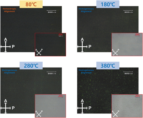
In addition, defects in the LC alignment state are clearly identifiable in crossed-polarizer mode. Distinct dark images for the 80°C, 180°C and 280°C samples were observed in crossed-polarizer mode. Although the LC alignment directions induced by the two samples are different, the LC molecules are aligned in one direction without dislocations. However, in crossed-polarizer mode, the image for the 180°C sample shows that line defects have occurred over the entire area due to reverse-aligned molecules among the LC molecules causing reverse-tilt-disclination. Light leakage occurs due to this phenomenon, which appears as line defects in the POM image. This means that in the 180°C sample, a large number of LC molecules were aligned in the reverse direction, and thus the film failed to fully control the light path. In conclusion, the results of the POM analysis indicate that the brush-coated HfSrO film cured at 80°C is suitable as a homeotropic alignment layer while the brush-coated HfSrO film cured at 280°C and 380°C are suitable as a homogeneous alignment layer.
The plots of transmittance curve vs. latitudinal rotation angle measured by the crystal rotation method shown in confirm the LC alignment and were used to calculate the pretilt angle of the LCs in the cell. The alignment direction of the LC molecules can be established through the wavenumbers from the transmittance curves. High-wavenumber graphs such as that for the 80°C sample are measured only in the homeotropic alignment state whereas low-wavenumber such as those for the 180, 280 and 380°C samples are measured only in the homogeneous alignment state.
Figure 7. Pretilt angle measurement of LC cells assembled with brush-coated HfSrO film cured at 80°C, 180°C, 280°C, and 380°C. The tilt-bias-angle transmittance measurement data is shown above, and the pre-tilt angle measurement value is shown as a graph below.
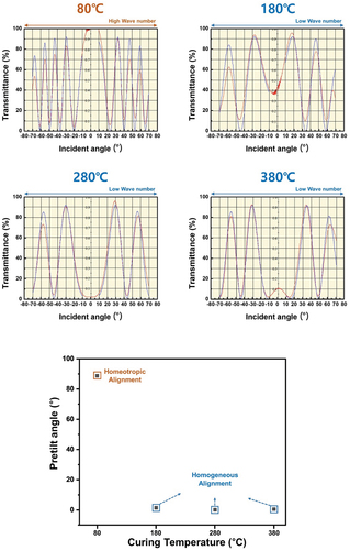
As exhibited in , a higher mismatch ratio between the red and blue lines indicates unstable and non-uniform LC alignment: the 180°C sample shows a large discrepancy rate whereas the 80 and 280°C samples show high correspondence rates. As confirmed by the POM analysis results, these results support the stable and uniform alignment of LC molecules in the 80 and 280°C samples. The alignment of the LC molecules in each sample was also confirmed by measuring the pretilt angle: that of the 80°C sample was 88.79° (indicating homeotropic alignment) while those of the 180, 280 and 380°C samples were 1.44°, 0.09° and 0.53° (indicating homogeneous alignment), respectively.
An LC cell was made with a brush-coated HfSrO film cured at 280°C and the polar anchoring energy was measured. The measured value was 2.44ⅹ10−4, which had sufficient strength to align the LC molecules.
shows the alignment state of LC molecules in LC cells assembled with brush-coated HfSrO films cured at low and high temperatures. From the surface analysis results, the low-temperature-cured brush-coated HfSrO film failed to form directional micro/nanostructures on the surface due to the presence of residual solvent. On the other hand, in the brush-coated HfSrO film cured at high temperature, directional micro/nanostructures formed a partial groove structure, which contributed to LC alignment due to surface anisotropy[Citation25]. The anisotropic structures create geometric restrictions at the boundaries with the LC molecules, as described by Berreman’s model [Citation26,Citation27] in which the LC molecules are subjected to a force in the direction that minimizes the free energy as follows:
Figure 8. Mechanism schematic diagram for homeotropic alignment and homogeneous alignment of HfSrO film.
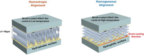
where K is the modulus of elasticity, f is the wavenumber of the groove, h is the height of the groove, and θ is the angle between the LC molecule and the direction of the groove. Thus, the higher the groove height and the shorter the groove period, the stronger the force that aligns the LC molecules homogeneously. Accordingly, homogeneous alignment occurred in the 280°C sample, homeotropic alignment occurred in the 80°C sample, and unstable homogeneous alignment occurred in the 180°C sample.
According to the Friedel-Creagh-Kmetz law, a difference in pretilt angle is closely related to the surface energy. At low surface energy (i.e. a high contact angle), the van der Waals forces between the alignment layer and the LC molecules are weak and the intermolecular forces between the LC molecules are strong. Hence, the LC molecules are aligned in the direction perpendicular to the alignment layer, as occurred in the 80°C sample with a high contact angle exhibiting the homeotropic alignment property. Conversely, high surface energy (i.e. a low contact angle) induces strong van der Waals forces that anchor the LC molecules parallel to the alignment layer, as occurred in the 280°C sample with a low contact angle exhibiting the homogeneous alignment property. In conclusion, the brush-coated HfSrO film can provide a homeotropic or a homogeneous LC alignment layer depending on the curing temperature.
4. Conclusions
We introduced a process-efficient homeotropic/homogeneous LC alignment layer via brush coating an HfSrO film depending on the curing temperature. Unlike LC orientation processes in which the film deposition step and the anisotropy formation step are separated, the brush-coating method generates anisotropy in the film during the deposition process. The surface modification and LC alignment characteristics of brush-coated HfSrO films cured at 80, 180, 280, and 380°C were analyzed. AFM analysis confirmed the formation of directional micro/nanostructures in the film cured at a temperature of 280°C or higher. The shear stresses created by the movement of the brush hairs formed partial microgrooves in the sol-state HfSrO film, and the grooves solidified at temperatures of 280°C or above. Anisotropic boundaries were generated in the microgrooves formed in this way so that LC molecules could be horizontally aligned in the grooves. In addition, the LC alignment property changed according to the surface energy of the HfSrO film. The high contact angle observed in the 80°C film indicates low surface energy that enabled homeotropic alignment due to weak van der Waals forces. Conversely, the low contact angle observed for the 280°C film indicates high surface energy that enabled homogeneous alignment due to strong van der Waals forces. Thus, surface modification according to the curing temperature led to different LC orientation characteristics. With HfSrO film produced at temperatures of 280°C or above, the LC molecules achieved stable and uniform homogeneous alignment whereas, at 180°C, they achieved unstable homogeneous alignment. Homeotropic alignment was observed with films produced at 80°C. Hence, we innovatively produced HfSrO films as homeotropic or homogeneous LC alignment layers depending on the curing temperature during a process-efficient brush-coating method.
Acknowledge
This research was supported by the National Research Foundation of Korea (Grant No. 2020R1G1A1013604).
Supplemental Material
Download MS Word (3.3 MB)Disclosure statement
No potential conflict of interest was reported by the author(s).
Supplementary material
Supplemental data for this article can be accessed online at https://doi.org/10.1080/19475411.2022.2116736
Additional information
Funding
References
- Wenhui W, Limin Q. Light management with patterned micro- and nanostructure arrays for photocatalysis, photovoltaics, and optoelectronic and optical devices. Adv Funct Mater. 2019;29:1807275.
- Nowduri B, Schulte S, Decker D, et al. Biomimetic nanostructures fabricated by nanoimprint lithography for improved cell-coupling. Adv Funct Mater. 2020;30:1–10.
- Talukdar TH, Perez JC, Ryckman JD. Nanoimprinting of refractive index: patterning subwavelength effective media for flat optics ACS. Appl Nano Mater. 2020;3:7377–7383.
- Baran J, Dolgov L, Gavrilko T, et al. Effect of clay surface modification on the structure and electro-optical properties of liquid crystal/clay nanocomposites. Philos Mag. 2007;87:4273–4285.
- Li X, Choy WCH, Huo L, et al. Dual plasmonic nanostructures for high performance inverted organic solar cells. Adv Mater. 2012;24:3046–3052.
- Koo WH, Jeong SM, Araoka F, et al. Light extraction from organic light-emitting diodes enhanced by spontaneously formed buckles. Nat Photonics. 2010;4:222–226.
- Kataoka M, Okada H. In-plane switching liquid crystal cells using patterned printing electrodes and fine groove structures. Liq Cryst. 2020;47:1735–1743.
- Song IH, Jeong HC, Lee JH, et al. Selective liquid crystal driving mode achieved by controlling the pretilt angle via a nanopatterned organic/inorganic hybrid thin film. Adv Opt Mater. 2021;9:1–8.
- Edinger S, Bansal N, Bauch M, et al. Highly transparent and conductive indium-doped zinc oxide films deposited at low substrate temperature by spray pyrolysis from water-based solutions J. Mater Sci. 2017;52:8591–8602.
- Laurenti M, Garino N, Porro S, et al. Zinc oxide nanostructures by chemical vapour deposition as anodes for Li-ion batteries. J Alloys Compd. 2015;640:321–326.
- Chin HS, Chao LS, Wu CC. Crystal, optical, and electrical characteristics of transparent conducting gallium-doped zinc oxide films deposited on flexible polyethylene naphthalate substrates using radio frequency magnetron sputtering. Mater Res Bull. 2016;79:90–96.
- Kim HY, Park YJ, Kim J, et al. Transparent InP quantum dot light-emitting diodes with ZrO2 electron transport layer and indium zinc oxide top electrode. Adv Funct Mater. 2016;26:3454–3461.
- Zhu Z, Mankowski T, Balakrishnan K, et al. Sol-gel deposition and plasma treatment of intrinsic, aluminum-doped, and gallium-doped zinc oxide thin films as transparent conductive electrodes. Thin Film Sol Energy Technol. 2015;9561:956109. VII
- Lee S, Chae W, Kim B, et al. New clues to the factors governing the perpendicular alignment of liquid crystals on rubbed polystyrene film surfaces. langmuir. 2003;19:8735–8743.
- Okoshi K, Fujiki M, Watanabe J. Asymmetrically tilted alignment of rigid-rod helical polysilanes on a rubbed polyimide surface.Langmuir. 2012;28:4811–4814.
- Luo L, Tang Z, Yang W, et al. Thickness-dependent photo-aligned thin-film morphologies of a block copolymer containing an azobenzene-based liquid crystalline polymer and a poly(ionic liquid. Langmuir. 2021;37:9774–9784.
- Kim DH, Lee DW, Oh JY, et al. Nanopatterning of polymer/gallium oxide thin films by UV-curing nanoimprint lithography for liquid crystal alignment ACS. Appl Nano Mater. 2022;5:1435–1445.
- Kim DH, Kim EM, Heo GS, et al. Anisotropy and surface morphology of polystyrene-block-poly(ethylene-ran-butylene)-block-polystyrene thin layer irradiated with ion beam. Liq Cryst. 2022;00:1–10.
- Kang H, Hwang BH, Baik HK, et al. Ion beam induced liquid crystal alignment properties of 4-alkylphenoxymethyl-substituted polystyrenes. Liq Cryst. 2010;37:179–187.
- Lee DW, Lee JH, Kim EM, et al. Surface modification of a poly(ethylene-co-vinyl acetate) layer by ion beam irradiation for the uniform alignment of liquid crystals. J Mol Liq. 2021;339:116700.
- Geary JM, Goodby JW, Kmetz AR, et al. The mechanism of polymer alignment of liquid‐crystal materials. J Appl Phys. 1987;62:4100.
- Neill MO, Kelly SM. Photoinduced surface alignment for liquid crystal displays. J Phys D: Appl Phys. 2000;33:R67.
- Shoichi I, Hirojumi W, Keizo N, et al. The effect of rubbed polymer films on the liquid crystal alignment Liq. Cryst. 1989;4:669–675.
- Kim JH, Yoneya M, Yokoyama H. Tristable nematic liquid-crystal device using micropatterned surface alignment. Nature Nature. 2002;420:159–162.
- Sinha GP, Rosenblatt C, Mirantsev LV. Disruption of surface-induced smectic order by periodic surface corrugations Phys. Rev. E . 2002;65:1–4.
- Berreman DW. Solid surface shape and the alignment of an adjacent nematic liquid crystal Phys. Rev Lett. 1972;28:1683–1686.
- Fukuda JI, Yoneya M, Yokoyama H. Surface-groove-induced azimuthal anchoring of a nematic liquid crystal: berreman’s model reexamined Phys. Rev Lett. 2007;98:1–4.