
 ?Mathematical formulae have been encoded as MathML and are displayed in this HTML version using MathJax in order to improve their display. Uncheck the box to turn MathJax off. This feature requires Javascript. Click on a formula to zoom.
ABSTRACT
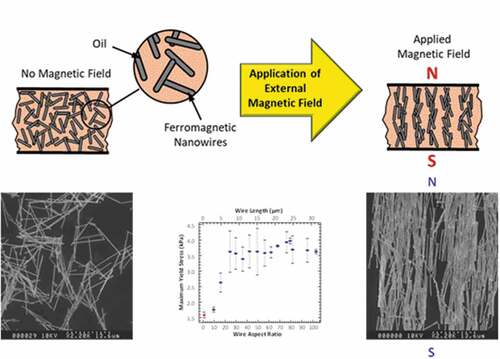
The yield stress of magnetorheological (MR) fluids has been shown to depend on particle morphology, but the exact nature of this contribution is still not fully understood. In this study, MR fluids containing 4 vol. % cobalt particles (spherical particles vs. nanowires) suspended in silicone oil were investigated. The influence of the aspect ratio on the rheological properties of suspensions that contained cobalt nanowires with aspect ratios ranging from 10 to 101 in increments of ~6 is described. The cobalt nanowires were fabricated using alumina template-based electrodeposition, producing wires with 305 ± 66 nm diameters. The shear stress was measured as a function of shear rate for increasing applied magnetic fields. The apparent yield stress and viscosity as a function of changing aspect ratio of the nanowire suspensions were determined. At a saturated magnetic flux density, the yield stress was found to increase linearly up to an aspect ratio of 23 (7.1 μm long wires) at which time the yield stress reached a plateau of 3.7 kPa even as the aspect ratio was further increased. As a comparison, suspensions containing 4 vol. % 1.6 μm spherical cobalt particles only reached a maximum yield stress of 1.6 kPa.
Graphical abstract
1. Introduction
Magnetorheological (MR) fluids are a type of smart material that consist of ferromagnetic micron-scale particles (typically spherical) suspended in a nonmagnetic carrier fluid such as hydrocarbon oil, silicon oil, or water [Citation1,Citation2]. Upon application of a magnetic field, the MR fluid becomes ‘activated’ and its viscosity increases proportionally with the magnitude of the field strength. With a high enough concentration of suspended ferromagnetic particles, typically on the order of 30 to 40 volume percent of particles, the viscosity of the activated suspension can increase to the order of 105 to 106 Pa·s such that it effectively becomes a semisolid [Citation2]. Thus, increasing the concentration of particles increases the yield strength of the activated suspension, but has the drawback of increasing the off-state viscosity as well. The transition time between the off-state (no magnetic field) and on-state (applied magnetic field) or vice versa of an MR fluid is on the order of 10 ms or less [Citation3]. The external magnetic field induces magnetic dipoles in the suspended particles, causing a magnetostatic interaction between the particles resulting in the formation of chains which collectively form complex fibrous columnar structures aligned along the field lines between the surfaces of the device containing the MR fluid [Citation4]. This causes the activated fluid to behave as a Bingham plastic fluid that displays an apparent yield stress. The on-state viscosity of these fluids is scalable with the applied magnetic field until magnetic saturation of the suspended particles is achieved, after which a maximum apparent yield stress is observed [Citation5]. Field-induced yield stresses of up to 100 kPa (in suspensions that contain close to 40 vol. % particles) have been observed [Citation6]. Once an external force is applied which is greater than the apparent yield stress, it is believed that the chains are constantly broken and reformed, resulting in a post-yield viscosity. Particle size, shape, composition, and concentration dictate the rheological, magnetorheological, and magnetic properties of the MR fluids [Citation2].
Currently, numerous applications exploit this material’s continuously controllable, field-dependent yield stress including variable dampers [Citation7,Citation8], brakes [Citation9], and clutches [Citation10], just to name a few. The use in new applications has been limited only by the characteristics of available MR fluids, specifically, apparent yield stress, settling rate, and the difference between the on- and off-state viscosities [Citation11].
The replacement of spherical particles with nanowires in MR fluids has greatly enhanced the properties of these unique smart materials and has begun to provide a better understanding of the physical mechanisms at play [Citation4,Citation12–24]. Both the yield stress and settling properties of magnetorheological fluids depend on particle morphology. It has been shown that wire-based MR fluids have major advantages over those suspensions that contain only spherical particles. The maximum achievable yield stress can be more than twice that of conventional suspensions at the same metal loading [Citation4,Citation13,Citation19] and provide a greater level of control of the viscosity and yield stress at field strengths below magnetic saturation of the suspension [Citation4]. A major drawback of wire-only suspensions is the low particle loading that can be achieved which is dependent on the aspect ratio and is normally less than 10 vol. %, far below the 30 to 40 vol. % required for most applications. This low loading is due to the large excluded volume of the particles [Citation25]. In a viscous suspension, the packing density of smooth spheres is 0.68 while it drops to 0.18 for randomly aligned ellipsoidal particles with an aspect ratio of 27 with no outside influences present, such as, shear or the presence a magnetic field [Citation26]. However, there is one tremendous advantage, these mixtures display a greatly reduced sedimentation rate and very low overall sedimentation, opening the door for many new applications [Citation4].
Another advantage of the wire-containing suspensions is the ease with which the particles can be redispersed after remaining idle for extended periods of time. Sedimentation and subsequently the tightly packed sediment formation of the particles is common in conventional MR fluids due to the large difference in densities between the particles and the carrier fluid [Citation27,Citation28]. Once sedimentation has occurred, the MR effect is lost until the fluids are vigorously mixed. This phenomenon has limited their use to turbulent environments, e.g. dampers and clutches, or in devices that do not rely on an immediate MR response, which would allow time for the particles to be redispersed in the carrier fluid after sedimentation. Problems associated with these issues have been partially reduced by the addition of thixotropic additives [Citation29–32], nanoparticles [Citation33,Citation34], nanowires [Citation4,Citation12,Citation18], and other non-spherical particles [Citation35–37].
Nanowires are ideally suited as model particles for the systematic experimental and theoretical study of shape-dependent properties of MR fluids due to their well-defined shape and controllable dimensions and composition. The coercivity, remanence, and magnetic saturation all depend on the composition and aspect ratio of the nanowires. López-López, et al. generated cobalt wires from the agglomeration of spherical cobalt particles prepared by reduction in polyols while stirred in a magnetic field [Citation13,Citation17,Citation20]. Wires of various lengths were produced by controlling the stirring frequency, temperature and time of mixing. This resulted in wires with fairly rough surfaces and rather large length and diameter distributions. Cobalt wires with an aspect ratio of 12.5 (60 μm long with 4.8 μm diameter) in a 1, 3, 5, and 7 vol. % suspension in silicone oil displayed a two- to four-fold increase in the maximum dynamic yield stress as compared to similar suspensions with spherical cobalt particles with diameters of 1.34 μm. An increase in the yield stress with increasing loading of ferromagnetic particles was observed, a similar behavior to suspensions of spherical particles. These same phenomena were observed for 7.6 μm long and 260 nm diameter iron nanowires as compared to suspensions with 1–3 μm diameter iron spheres [Citation4]. Kuzhir, et al. indicated the enhancement of the magnetorheological effect of suspensions containing ferromagnetic rod-like particles was due to interfiber friction [Citation16,Citation17].
In this study, we investigate the effects of aspect ratio on the rheological and magnetorheological properties of MR fluids and compare these findings with the values found for fluids that contain conventional spherical particles.
2. Experimental details
Two types of cobalt particles were examined in this study. The quasi-spherical cobalt particles with nominal 1.6 μm diameters (Alfa Aesar) were used as purchased and the cobalt nanowires were generated via template-based electrodeposition. Both particle types were suspended in silicone oil.
2.1 Nanowire production
Cobalt nanowires were generated via template-based electrodeposition using commercially available anodized alumina membranes (Whatman) as templates. The electrolytic solution consisted of 0.2 mol/L CoSO4, 0.02 mol/L CoCl2, 0.3 mol/L H3BO3 adjusted to a pH of 3.5 using H2SO4. Pure cobalt electrodes (99.97%) were suspended 2 cm from the alumina template in the cobalt solutions. Wires were electrodeposited at a constant potential of 1.5 V at a current density of 5.2 mA cm−2 under ambient conditions without agitation. Wire length was controlled by the deposition time. Nanowires were recovered by dissolving the wire filled template in a 1 mol/L sodium hydroxide solution.
2.2 Nanowire characterization
The electrodeposition of cobalt in the alumina templates produces wires with 305 ± 66 nm diameters (n = 4164). The lengths of the wires were controlled within a range of 1.77 to 30.97 μm resulting in aspect ratios ranging from 10 to 101. Dimensional information and size distribution for the nanowires was obtained using a Hitachi S570 and Hitachi S800 scanning electron microscopes (SEM). The physical characteristics of the spheres and wires can be seen in the SEM micrographs in , respectively. gives the various lengths and distributions of the wires used in this study.
Figure 1. SEM micrograph of quasi-spherical cobalt particles with nominal 1.6 μm diameters as reported by the manufacturer.
Figure 2. SEM micrograph of 10.98 ± 1.98 μm long cobalt nanowires with 305 ± 66 nm diameter.
Table 1. Average length and size distribution of the cobalt nanowires in which n number of wires were evaluated of each type. All wires had an average diameter of 305 ± 66 nm.
The stoichiometric composition of the nanowires was determined using an induction-coupled plasma spectrometer (ICP). The ICP results indicate that the wires do not contain significant amounts of other metals. In particular, none of the metals (gallium, indium, copper, or aluminum) that come in contact with the wires during fabrication were detected.
X-ray diffraction (XRD) patterns, shown in , were collected using a Scintag X2 diffractometer to determine the bulk crystal structure and approximate grain size of the crystallites forming the nanowires generated through template-based electrodeposition. X-ray diffraction of the free wires indicates that cobalt grows in a hcp polycrystalline structure consistent with the formation of cobalt nanowires generated via template-based electrodeposition [Citation38–40]. The approximate crystallite size for as-deposited cobalt wires is 42 nm as determined from Scherrer’s formula. There was no indication of an oxidized phase present in the nanowire samples analyzed.
Figure 3. XRD of cobalt wires in which the lattice planes are indicated in () brackets. The spectra indicates that the cobalt crystal structure is hexagonal close packed with no peaks present for an oxide layer.
The magnetic properties of the nanowires were determined using a Lakeshore 7400 series vibrating sample magnetometer (VSM) at room temperature. The M-H curves for nanowires in the alumina template are shown in . Since the saturation magnetization is obtained when all magnetic moments in the material are aligned in the same direction, it is a property of the ferromagnetic material and hence is independent of particle geometry. Therefore, we would expect both the spheres and nanowires to have a similar saturation magnetization to that of bulk cobalt (1398 emu cm−3) excluding differences due to shape and crystalline anisotropies due to strain. The magnetic saturation of spheres was measured as 1119 emu cm−3 and for the nanowires, in the alumina template, this value dropped to 989 emu cm−3. For the calculation of the specific magnetization in emu g−1, the overall mass of the measured sample (i.e. template with embedded nanowires) was considered.
Figure 4. Hysteresis loops of cobalt nanowires within the alumina template measured at 298 K. The dotted line was measured with the applied field parallel to the long axis of the nanowires. The solid line was measured with the applied field perpendicular to the long axis of the nanowires.
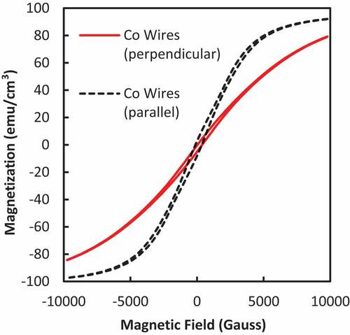
The final orientation of the effective magnetic easy axis for an isolated nanowire depends on both the magnetocrystalline and shape anisotropies [Citation41]. The hysteresis loops in indicate that the magnetocrystalline anisotropy for the HCP-Co favors the magnetization to be preferentially oriented along the (002) direction (i.e. along the long axis of the nanowire) [Citation39]. When the length of a wire is much larger than its diameter, the easy axis of the magnetization tends to be aligned along the wire length due to its large shape anisotropy [Citation41,Citation42].
2.3 Formulation of MR fluids
Magnetorheological fluids were prepared using a 0.18 Pa·s viscosity silicone oil (GE SF96-200). To enhance dispersion, lecithin was added as a surfactant at 2 wt% of the total mass of the cobalt particles. The lecithin was thoroughly mixed into the oil before addition of the cobalt particles. In this study, we choose a particle loading of 4 vol% since the maximum particle loading is dependent upon the length (or aspect ratio) of the particles. That is the longer the particles, the lower the total achievable loading due to the increase in the excluded volume of the longer particles. In addition, the suspensions were characterized by a high degree of wire dispersion, i.e. few wire bundles were present. These bundles would effectively lower the aspect ratio of the suspensions.
2.4 Rheology of MR fluids
The steady-state rheological measurements were made on an Anton-Paar Physica MCR300 parallel disc rheometer equipped with a MRD180 cell. A standard gap of 1 mm was maintained between the discs. A Hall probe (F.W. Bell FH301) was placed within the gap to calibrate the input current of the rheometer in terms of the magnetic flux density experienced within the fluid containing gap. A magnetic flux density of up to 1.0 T (4 A) was applied to the fluids in this study. The temperature of all samples was maintained at 25°C through a closed cycle cooling system.
Rotational tests were carried out to determine the flow curves (shear stress vs shear rate). A 0.3 mL sample was placed between the disks. Since we are working with fluids with low vol % particles and the rheometer is not designed to contain low viscosity fluids, special precautions are taken to avoid expulsion of the fluid from between the disks at high shear rates and to prevent sedimentation of the particles before testing. Both of these issues were avoided by using a fairly viscous silicone oil (0.18 Pa·s). Sedimentation of the MRF samples at these wire loadings was not an issue, however, to avoid sedimentation, the tests were started as soon as the thoroughly mixed fluid was inserted between the disks.
3. Results and discussion
3.1 Rheology of MR fluids
The steady-state flow curves for which the shear stress, τ, versus the shear rate, , were measured using the parallel disk rheometer. A Bingham-plastic (BP) constitutive model [Citation43] was fitted to the flow curve in a parameter identification procedure to determine the dynamic (Bingham) yield stress, τy, and the post-yield viscosity (plastic viscosity), η. The equation for this generalized model for the viscoplastic flow with yield stress is given by
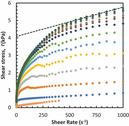
By using the measured shear rates as the weights, the model provided a better fit to the high shear rate data. An example of this is shown in for 4 vol % fluids containing 7.1 μm nanowires. All suspensions displayed typical MR behavior in which the shear stress and viscosity at a given shear rate increased with magnetic field intensity. All fluids were tested an average of 7 times with a minimum of 3 times. Flow curves without an applied magnetic field were collected at a maximum shear rate of only 400 s−1 as there was almost no curvature in these data after this point. For all samples in which a field was applied, the data was collected up to a maximum shear rate of 1000 s−1.
Figure 5. Experimental flow curves for fluids containing 4 vol% 7.05 μm long nanowires with the Bingham-plastic (BP) model fit superimposed (dotted line). The applied magnetic field was varied from 0.00 T (bottom) to 0.96 T (top) in increments of ~0.08 T.
The dynamic yield stress displays a strong dependence on the applied magnetic field as seen in . The yield stress steadily rose as the magnetic field was increased until the saturation of the magnetization of the particles was reached and the yield stress plateaued. The maximum yield stress was determined at the saturated magnetic flux density and reported as the average for each set of samples. This was the case for all suspensions studied. The maximum yield stress was achieved at a field strength between 0.5 and 0.58 T for the sphere-based sample and the wire samples with an aspect ratio up to 16. All samples above an aspect ratio of 16 all reached a maximum yield stress at 0.65 T. The maximum yield stresses for each set of samples with the same aspect ratio were determined as the average of the last four points of the each set of data.
Figure 6. The yield strength versus magnetic field (at a 95% confidence interval) for fluids containing 4 vol. % of 4.82 μm long cobalt nanowires.
3.2 Shape and aspect ratio dependent field stress
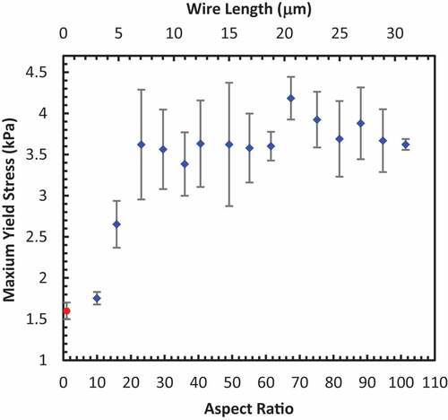
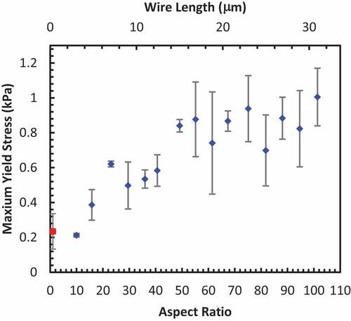
The dynamic yield stress displays a strong dependence on the shape of the particles as seen in . The quasi-spherical particles with an aspect ratio of ~1 display a maximum yield stress of 1.6 kPa, while the shortest wire suspension tested with an aspect ratio of 10 (3.04 μm long wires) reaches 1.8 kPa. The maximum yield stress increases to 3.6 kPa at an aspect ratio of 23 (7.05 μm wires) and then levels off at approximately this value as the aspect ratio continues to increase. For suspensions of spherical particles, the Bingham yield stress represents the force required to break the field-induced particle chains and columnar structures in order for the MR fluid to yield. For the suspension of ferromagnetic wires, the application of a magnetic field is expected to result in intertangled dendrite-like networks that are more robust than the chain-like structures formed by the spherical particles. Therefore, we would expect the Bingham yield stress of a suspension of wires to be higher than that of the equivalent suspension of spheres. As expected, the wires display a greater than two-fold increase in the maximum yield stress as compared to the spherical particles.
Figure 7. The maximum yield strength (at a 95% confidence interval) of the cobalt microwire-based MR fluids at 4 vol. % increase (diamonds) as the aspect ratio is increased until an aspect ratio of 23 at which time the maximum yield stress plateaus at 3.7 kPa. This is more than double the maximum yield of 1.6 kPa achieved for fluids containing the more conventional spherical particles (circle) at the same loading.
The reason for the enhancement is likely due to a number of factors including the greater induced magnetic moment that occurs for elongated particles due to their smaller demagnetization factor in the long direction [Citation18]. Another factor may result from the entanglement of fibers at higher particle loadings making the breaking of the columnar fibral structures more difficult. Yet another possible contributing factor is the existence of a field-dependent solid friction between the wires [Citation13,Citation17,Citation22]. For the columnar structures to break, the wires would have to slide over one another with more surface-to-surface contact with one another compared to that of spherical particles. In addition, particle roughness tends to increase the static yield stress [Citation44,Citation45]. However, in this study, the quasi-spherical particles display a greater surface roughness as compared to the wires; thus, the spherical particle suspensions may have displayed a slight enhancement in the yield stress due to this factor as well.
The leveling-off of the maximum yield stress with increasing wire length (aspect ratio) is contradictory to what was found in de Vicente’s study in which they observed a constant increase in the yield stress with respect to the aspect ratio followed by a dramatic increase in yield stress after an aspect ratio of 116 [Citation43]. Their study used very low volume percent samples (0.5 vol. %). The low volume percent of wires is likely to limit the role of entanglement which resulted in the steady increase in yield stress with increasing aspect ratio.
The rheology of fiber suspensions is difficult to model due to the complexity of the multitude of interactions including such factors as fiber–fiber, fiber–wall, and fiber–matrix interactions. In addition, fiber breakage and bending must also be considered. Despite these challenges, a large number of experimental and theoretical investigations have been devoted to the analysis and prediction of the magnetorheological behavior of suspensions containing wire-shaped particles [Citation12,Citation13,Citation16–21,Citation24]. However, the theoretical studies have focused on dilute suspensions due to the enormous complexity of concentrated suspensions.
Particles immersed in a fluid exhibit long-ranged ordering as they move, and similarly move in response to fluid motion. By generating and reacting to a fluid’s local velocity, the suspended particles experience hydrodynamic interactions with each other and with the walls of their container. However, due to the loading of particles in this study where there are significant numbers of inter-wire contacts, hydrodynamic interactions are likely of secondary importance [Citation46]. The stresses with the application of the magnetic field is the result of frictional forces between particles as the local volume fraction exceeds the maximum packing fraction of fibers causing the fibers to bend elastically and exert contact normal forces on each other. When a shear force is applied, the fibers must slide against each other producing frictional forces.
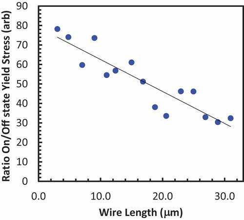
A plot of the increment in yield stress (the ratio of the maximum yield stress, τmax, to the off-field yield stress, τ0) versus the length of the wires clearly displays a decrease with wire length as shown in . This could be an indication that an increase in the passive yield stress and/or an increase in viscosity may be occurring. As the aspect ratio of the fibers increase, the fiber flexibility increases, and the viscosity decreases considerably, especially for the fibers with a high aspect ratio. However, the viscosity is expected to become independent of the aspect ratio at high shear rates [Citation47].
Figure 8. Plot of the increment in yield stress, i.e. the maximum yield stress at maximum field to the field off yield stress, τmax/τ0, versus the wire length clearly display a decrease with increasing wire length.
Another possible factor is the inability of the wires with the larger aspect ratios at the volume fractions tested to form the same well-formed fibrous columns in the field direction as the shorter aspect ratio wires. A possible contribution to the leveling off effect may be due to the way in which the wires line up in the magnetic field. Kuzhir, et al. calculated that fibers lined up in a zigzag structure displayed the lowest yield stress while fibers that lined up in a columnar structure would display the highest yield strength [Citation16]. These more isotropic structures may act as compressed springs which allow the wires to bend and slip more easily than the shorter wires.
In order to understand why the maximum yield displayed a plateau in terms of wire alignment, suspensions of wires of various lengths were prepared in methanol and a magnetic field was applied until the liquid completely evaporated locking in the structure of the suspensions due to electrostatic interactions. These samples were then examined in a scanning electron microscope (SEM) as shown in . The exact loading of these suspensions was not determined as the wires do not remain suspended in such a low viscosity fluid, but represent the max loading for each length of wire. Due to the smaller excluded volumes, the shorter wires can achieve higher loading as seen by the more densely pack columns compared to the longer wires as seen in these images. The change from a columnar structure for the short 7.05 μm long wires to a more zigzag structure for the 16.84 and 30.97 μm long wires can be seen in . In the absence of a magnetic field, the fibers form an entangled network with approximately isotropic orientation of the fibers. With a magnetic field applied, the shorter wires lined up relatively well, and formed agglomerates, which led to a reduction in viscosity [Citation48,Citation49]. The longer wires displayed less alignment with the field due to either passive static friction or entanglement or a combination of both. To simulate a shear stress, a glass slide was dragged along the surface of the suspensions while still in methanol and the magnetic field. The wires displayed rearrangements and/or reorientation becoming more aligned with one another, but the longer wires did not achieve the degree of alignment that the shorter wires did. These images are not shown for brevity and were similar to the results observed by López-López, et al. in a similar experiment [Citation17]. The wires become more aligned under stress and begin to slant. As this occurs, the wires start to align more with one another resulting in more surface-to-surface interactions between wires. At this point, the wires could begin slipping away from one another but will have much greater frictional energy than that of spherical particles due to the greater surface-to-surface contact. There is 3.5 times more surface area for the same vol. % of wires in an MR fluid as compared to spherical particles.
Figure 9. SEM micrographs of (a-c) 7.05, (d-f) 16.84, and (g-i) 30.97 μm long wires at various magnetic fields. The length scale bar represents the size for all image in that column. For the images in (a), (d), and (g), there is no magnetic field applied. The rest of the images are in a 338 mT field.
Due to the aspect ratio of the longer wires, it is possible at high enough stresses the wires may bend resulting in plastic deformation of the wires or breakage resulting in a suspension with particles that have a smaller overall aspect ratio. However, SEM images of the wires before and after the rheological tests indicate that the wires did not undergo plastic deformation or fracture. As the fiber aspect ratio increases, the critical stress needed for fiber bending decreases. Forgacs and Mason derived an equation for the critical stress at which a fiber would buckle as follows [Citation50]:
where Eb is approximately 2Ey, twice the Young’s modulus of the material. For bulk cobalt, the Young’s modulus is 160 GPa; however, this value was found to be lower for cobalt nanowires, 145 GPa [Citation51], and will vary depending on the conditions for which the wires were generated (the wires used in this study were not annealed and were deposited at room temperature) [Citation52]. With an apparent aspect ratio, r, of 100, the critical stress required to bend the wire would be 5.15 kPa, which is lower than the plateau yield stress of 3.7 kPa maximum yield stress observed in our study. However, this is an estimate and well within the realm of possibility. This value jumps to 802 kPa at an aspect ratio of 25.
3.3 Off-state viscosity
Fluids consisting of rod-like particles display distinctly different viscoelastic properties as compared to fluids that contain strictly spherical particles. That is, the static (kinematic) viscosity is much greater for the wire-based suspensions as compared to the sphere-based suspensions. This is due to the shape of the particles and how they align upon the application of a shear force. With no force applied the wires tend to align randomly with one another owing to their enhanced sedimentation properties [Citation4,Citation35], but the particles tend to line up along the lines of applied force greatly reducing the dynamic viscosity compared to that of the static viscosity with no external magnetic field applied.
The nanowire-based fluids demonstrate a steady increase in the off-state viscosity as the aspect ratio of the particles increase as determined from the BP model fit of the rheological data as shown in . At an aspect ratio of ~50, the off-state viscosity increases at a slower rate with increasing aspect ratio. The increase in the off-state viscosity is most likely a result of several factors, including wire entanglement, increased surface area compared to spheres, and interactions between wires, particularly those due to remnant magnetization and friction. The surface area of the different aspect ratio wire samples at the same volume fraction will be approximately the same with a small decrease with increasing aspect ratio (less than 5% in the different length of wires used in this study). The 1.6 μm spherical particles will have a total surface area approximately three and a half times lower at the same volume fraction of particles. Another factor influencing the difference in off-state viscosity is due to entanglement of the wires; that is, the constraint that the wires cannot pass through one another [Citation53]. The end-over-end rotational motion of the rods and translational motion of the rods perpendicular to the long axis are greatly restricted by the other wires. This effect will be enhanced by the increasing length of the wires and is most likely responsible for the steady increase in the viscosity with increasing aspect ratio. However, assuming that the wires are able to bend more easily as the aspect ratio increases, the effect on the viscosity is expected to decrease [Citation54].
Figure 10. The off-state viscosity of the cobalt sphere-based (circle) and nanowire-based (diamonds) MR fluids at 4 vol. % (at a 95% confidence interval). The nanowire-based MR fluid viscosity increases as the aspect ratio increases until an aspect of ~50 at which time the viscosity reaches a plateau of approximately 0.85 Pa·s.
It is the microstructure of the composite nanowire suspensions in the off-state that accounts for the greatly reduced settling. Entanglement of the wires does not allow them to freely move efficiently under the force of gravity alone. This results in a higher apparent viscosity relative to the viscosity under shear. The sphere-based fluids are able to quickly settle and pack efficiently due to their highly symmetric geometry.
4. Conclusions
The rheological behavior of MR fluids containing ferromagnetic wires, rod-like particles, display a strong dependence on the aspect ratio of the particles. The SEM images of the wires in a magnetic field show how the shorter aspect ratio particles pack more densely than the longer ones. At first, the maximum yield stress increases with increasing aspect ratio as would be expected due to an enhancement in interparticle magnetic interactions which would facilitate the rotation and translation of the particles within the suspension resulting in more compact aggregates. However, at an aspect ratio of 23, the maximum yield stress plateaus, which is likely due to a number of factors including the inability of the particles to align (to translate or rotate) due to frictional forces and entanglement. Another factor could be the elastic deformation of the wires at the higher stress. At this loading and aspect ratio, the frictional forces between particles overcome the magnetostatic interactions preventing the more compact columnar structures to form as compared to the smaller aspect ratio wires. The off-state viscosity displayed a steady increase as the aspect ratio of the particles increased until an aspect ratio of ~50 at which point the off-state viscosity increased at a slower rate as the aspect ratio continued to increase.
Disclosure statement
No potential conflict of interest was reported by the author(s).
Additional information
Funding
References
- Klingenberg DJ. Magnetorheology: applications and challenges. AlChE J. 2001;47(2):246–249.
- de Vicente J, Klingenberg DJ, Hidalgo-Álvarez R. Magnetorheological fluids: a review. Soft. Matter. 2011;7(8):3701–3710.
- Rabinow J. The magnetic fluid clutch. AIEE Trans. 1948;67:1308–1315.
- Bell RC, Karli JO, Vavreck AN, et al. Magnetorheology of submicron diameter iron microwires dispersed in silicone oil. Smart Mater Struct. 2008;17(1):015028 (6pp).
- Jones TB, Saha B. Nonlinear interactions of particles in chains. J. Appl. Phys. 1990;68(2):404–410.
- Phulé PP, Ginder JM. Synthesis and properties of novel Magnetorheological fluids having improved stability and redispersibility. Int J Mod Phys B. 2019-2027;13(14–16):1999.
- Kamath GM, Wereley NM, Jolly MR. Characterization of magnetorheological helicopter lag dampers. J. Am. Helicopter Soc. 1999;44(3):234–248.
- Choi SB, Nam MH, Lee BK. Vibration control of a MR seat damper for commercial vehicles. J Intell Mat Syst Struc. 2000;11(12):936–944.
- Wang N, Li DH, Song WL, et al. Effect of surface texture and working gap on the braking performance of the magnetorheological fluid brake. Smart Mater Struct. 2016;25(105026):13.
- Kavlicoglu NC, Kavlicoglu BM, Liu Y, et al. Response time and performance of a high-torque magneto-rheological fluid limited slip differential clutch. Smart Mater. Struct. 2007;16(1):149–159.
- Kumar JS, Paul PS, Raghunathan G, et al. A review of challenges and solutions in the preparation and use of magnetorheological fluids. Int. J. Mech. Mater. Eng. 2019;14(1):1–18.
- Bell RC, Miller ED, Karli JO, et al. Influence of particle shape on the properties of magnetorheological fluids. Int J Mod Phys B. 2007;21(28n29):5018–5025.
- López-López MT, Vertelov G, Bossis G, et al. New magnetorheological fluids based on magnetic fibers. J. Mater. Chem. 2007;17(36):3839–3844.
- Ngatu GT, Wereley NM, Karli JO, et al. Dimorphic Magnetorheological fluids: exploiting partial substitution of microspheres by nanowires. Smart Mater Struct. 2008;17(4):045022 (8pp).
- Gómez-Ramírez A, López-López MT, Durán JDG, et al. Influence of particle shape on the magnetic and magnetorheological properties of nanoparticle suspensions. Soft Matter. 2009;5(20):3888–3895.
- Kuzhir P, López-López MT, Bossis G. Magnetorheology of fiber suspensions. II. Theory. J. Rheol. 2009;53(1):127–151.
- López-López MT, Kuzhir P, Bossis G. Magnetorheology of fiber suspensions. I. Experimental. J. Rheol. 2009;53(1):115–126.
- de Vicente J, Segovia-Gutiérrez JP, Andablo-Reyes E, et al. Dynamic rheology of sphere- and rod-based magnetorheological fluids. J Chem Phys. 2009;131(194902):(10.
- de Vicente J, Vereda F, Segovia-Guitérrez JP, et al. Effect of particle shape in magnetorheology. J. Rheol. 2010;54(6):1337–1362.
- Kuzhir P, Gómez-Ramírez A, López-López MT, et al. Non-linear viscoelastic response of magnetic fiber suspensions in oscillatory shear. J. Non-Newtonian Fluid Mech. 2011;166(7–8):373–385.
- Gómez-Ramírez A, Kuzhir P, López-López MT, et al. Steady shear flow of magnetic fiber suspensions: theory and comparison with experiments. J. Rheol. 2011;51(1):43–67.
- Bossis G, Marins JA, Kuzhir P, et al. Functionalized microfibers for field-responsive materials and biological applications. J Intell Mat Syst Struc. 1871-1879;26(14):2015.
- Dong X, Tong Y, Ma N, et al. Properties of cobalt nanofiber-based magnetorheological fluids. RSC Advances. 2015;5(18):13958–13963.
- Morillas JR, Carreón-González E, de Vicente J. Effect of particle aspect ratio in magnetorheology. Smart Mater Struct. 2015;24(125005):13.
- Celzard A, McRae E, Deleuze C, et al. Critical concentration in percolating systems containing a high-aspect-ratio filler. Phys Rev B. 1996;53(10):6209–6214.
- Metzner A. Rheology of Suspensions in Polymeric Liquids. J. Rheol. 1985;29(6):739–775.
- Phule P, Mihalcin M, Genc S. The role of the dispersed-phase remnant magnetization on the redispersibility of magnetorheological fluids. J. Mater. Res. 1999;14(7):3037–3041.
- Aruna MN, Rahman MR, Joladarashi S, et al. Investigation of sedimentation, rheological, and damping force characteristics of carbonyl iron magnetorheological fluid with/without additives. J Braz Soc Mech Sci Eng. 2020;42(5):228.
- Weiss KD, Nixon DA, Carlson JD, et al., Thixotropic magnetorheological materials, US Patent No. 5,645,752 (1997).
- de Vicente J, López-López MT, González-Caballero F, et al. Rheological study of the stabilization of magnetizable colloidal suspensions by addition of silica nanoparticles. J Rheol. 2003;47(5):1093–1109.
- Lim ST, Cho MS, Choia HJ, et al. Magnetorheological characterization of organoclay added carbonyl-iron suspensions. Int J Mod Phys B. 2005;19(7–9):1142–1148.
- Song KH, Park BJ, Choi HJ. Effect of magnetic nanoparticle additive on characteristics of magnetorheological fluid. IEEE Trans Magn. 2009;45(10):4045–4048.
- Rosenfeld N, Wereley NM, Radakrishnan R, et al. Behavior of magnetorheological fluids utilizing nanopowder iron. Int J Mod Phys B. 2002;16(17n18):2392–2398.
- Wereley NM, Chaudhuri A, Yoo JH, et al. Bidisperse Magnetorheological fluids using fe particles at nanometer and micron scale. Journal of Intelligent Material Systems and Structures. 2006;17(5):393–401.
- Yin J, Zhao X. Titanate nano-whisker electrorheological fluid with high suspended stability and ER activity. Nanotechnology. 2006;17(1):192–196.
- Vereda F, Segovia-Gutiérrez JP, de Vicente J, et al. Faceted particles: an approach for the enhancement of the elasticity and the yield-stress of magnetorheological fluids. Appl Phys Lett. 2016;108(211904):4.
- Anupama AV, Choudhary HK, Kumar R, et al. Steady-shear response of magnetorheological fluid containing coral-shaped yttrium-iron-garnet particles. Mater Res Bull. 2019;113:45–50.
- Cantu-Valle J, Betancourt I, Sanchez JE, et al. Mapping the magnetic and crystal structure in cobalt nanowires. J. Appl. Phys. 2015;118(2):024302.
- Maaz K, Karim S, Usman M, et al. Effect of Crystallographic Texture on Magnetic Characteristics of Cobalt Nanowires. Nanoscale Res. Lett. 2010;5(7):1111–1117.
- Xua J, Huangb X, Xiea G, et al. Fabrication and magnetic property of monocrystalline cobalt nanowire array by direct current electrodeposition. Mater Lett. 2005;59(8–9):981–984.
- Kröll M, Blau WJ, Grandjean D, et al. Magnetic properties of ferromagnetic nanowires embedded in nanoporous alumina membranes. J Magn Magn Mater. 2002;249(1–2):241–245.
- Fert A, Piraux L. Magnetic nanowires. J. Magn. Magn. Mater. 1999;200(1–3):338–358.
- Jolly M, Bender J, Bender J. Properties and applications of commercial MR fluids. J. Intel. Mat. Syst. Str. 1999;10(1):5–13.
- Vereda F, Segovia-Gutiérrez JP, de Vicente J, et al. Particle roughness in magnetorheology: effect on the strength of the field-induced structures. J Phys D Appl Phys. 2015;48( 015309):11.
- Vereda F, de Vicente J, Hidalgo-Álvarez R. Effect of surface roughness on the magnetic interaction between micron-sized ferromagnetic particles: finite element method calculations. J Intell Mat Syst Struc. 2017;28(8):992–998.
- Sundararajakumar RR, Koch DL. Structure and properties of sheared fiber suspensions with mechanical contacts. J. Non-Newtonian Fluid Mech. 1997;73(3):205–239.
- Keshtkar M, Heuzey MC, Carreau PJ. Rheological behavior of fiber-filled model suspensions: effect of fiber flexibility. J. Rheol. 2009;53(3):631–650.
- Tao R. The physical mechanism to reduce viscosity of liquid suspensions. In: Gordaninejad F, Graeve OA, Fuchs A, et al., editors. Electrorheological fluids and magnetorheological suspensions proceedings of the 10th international conference on ERMR. Vol. 2007, New Jersey: World Scientific Publishing Company, Inc.; 2006. p. 21–28.
- Tao R, Xu X. Reducing the viscosity of crude oil by pulsed electric or magnetic field. Energy Fuels. 2006;20(5):2046–2051.
- Forgacs OL, Mason SG. Particle motions in sheared suspensions IX. Spin and deformation of threadlike particles. J. Colloid Sci. 1959;14(5):457–472.
- Zhang D, Breguet J-M, Clavel R, et al. In situ tensile testing of individual Co nanowires inside a scanning electron microscope. Nanotechnology. 2009;20(365706):(6.
- Esfahani MN, Alaca BE. A review on size-dependent mechanical properties of nanowires. Adv Eng Mater. 2019;21(1900192):23.
- Doi M, Edwards SF. Dynamics of rod-like macromolecules in concentrated solution. J Chem Soc Faraday Trans. 1978;74(3):560–570.
- Switzer LH, Klingenberg DJ. III and D. J. Klingenberg. Rheology of sheared flexible fiber suspensions via fiber-level simulations. J. Rheol. 2003;47(3):759–778.