
 ?Mathematical formulae have been encoded as MathML and are displayed in this HTML version using MathJax in order to improve their display. Uncheck the box to turn MathJax off. This feature requires Javascript. Click on a formula to zoom.
ABSTRACT
Flexoelectric effect can be used to design actuators to control engineering structures including beams, plates, and shells. Multiple flexoelectric actuators method has the advantage of less stress concentration and better control effect, but the mode-dependent optimal actuator locations could influence the flexoelectric actuation effect significantly. In this work, a neural network model is established to study the optimal combinations of multiple flexoelectric actuators on a rectangular plate. In the physical model, an atomic force microscope (AFM) probe was employed to generate an electric field gradient in the flexoelectric patch, so that flexoelectric control force and moment can be obtained. Multiple flexoelectric actuators on the plate was considered. Case studies showed that the flexoelectricity induced stress mainly concentrate near the probe, the size and shape of the flexoelectric patch have limited effect on the actuation, hence, only the actuator positions were choosing as the input of the ANN model. Using the prediction of the neural network model, the driving effect of a large number of actuators at different positions can be quickly obtained, and the optimal position of the actuator can be analyzed more accurately.
GRAPHICAL ABSTRACT
Introduction
In the past ten years, precision actuation has been applied to fields such as biomedicine, precision manufacturing, aerospace, as well as semiconductor and microelectronics [Citation1–4]. Smart materials can be used as actuators to achieve precise actuation and active vibration control, among which piezoelectric materials [Citation5], shape memory alloy [Citation6], magnetostrictive materials [Citation7], electrostrictive materials [Citation8], electro/magnetorheological fluids (ERF/MRF) [Citation9,Citation10] are the most widely used. Flexoelectricity is an electromechanical coupling effect and exists in all solid dielectric materials [Citation11,Citation12]. Compared with piezoelectricity, it does not need prepolarization and is not restricted by the Curie temperature [Citation13]. Because of these characteristics, the research of flexoelectric materials as actuators and sensors has attracted more and more attention [Citation14,Citation15].
Direct flexoelectric effect describes the linear relationship between stress gradient and electric field in dielectric materials, and converse flexoelectric effect describes the linear relationship between electric field gradient and stress in dielectric materials. Based on converse flexoelectric effect, it can be applied to actuation and active vibration control of micro-nanostructures. Fu et al. [Citation16] reported the converse flexoelectric effect in Ba0.67Sr0.33TiO3 (BST) and measured the flexoelectric coefficient of the BST sample through experiments. Based on the direct flexoelectric effect, Hu et al. [Citation17] proposed the distributed dynamic sensing using flexoelectric materials, and defined flexoelectric signal of distributed flexoelectric sensors laminated on an arbitrary shell structure. The open-circuit and the close-circuit models of distributed flexoelectric sensing are established, which proves that the distributed sensing based on flexoelectricity is feasible. In soft robotics, distributed sensing and actuation give robots new capabilities. Since soft robot motion is mainly based on deformation, the integration of pneumatic or hydraulic valves or small motors for tendon-driven systems, and the distribution of sensor across their bodies facilitate the control of their complex motion and the monitoring of their interaction with the environment [Citation18]. Wu et al. [Citation19] proposed a biconcave beam structure and actuation method based on the converse flexoelectric effect, which provides a non-uniform structure to generate an electric field gradient, and this method can be applied to flexoelectric actuators. The key to using converse flexoelectric effect is to generate inhomogeneous electric field, and atomic force microscope (AFM) probe can generate high inhomogeneous electric field [Citation20]. Fan et al [Citation21]. constructed an electric field gradient by placing AFM probe on the flexoelectric patch to produce stress inside the flexoelectric material. The induced flexoelectric stress and bending moment can be used to control the vibration of the beam. Zhang et al. [Citation22] designed a flexoelectric actuation method induced by a line-electrode to control the vibration of a plate. The electric field gradient is generated through the line-electrode, which induces the bending moments inside the flexoelectric layer laminated on the thin plate to affect the vibration of the plate. Hamid et al [Citation23]. present a design methodology based on a combination of isogeometric analysis (IGA), level set and point wise density mapping techniques for topology optimization of piezoelectric/flexoelectric materials. This computational methodology contributes to design of micro and nano-scale flexoelectric devices with optimized electromechanical conversion efficiency.
The flexoelectric material is used as an actuator, in order to achieve a good actuation and control effect, the most direct way is to increase the applied voltage, but this will lead to stress concentration phenomenon, causing fatigue problems in the actuator structure. Compared with changing the material properties and structural parameters of the actuator, increasing the number of actuators can reduce the voltage applied on each actuator, weaken the influence of stress concentration, and achieve a good control effect. The control method using multiple actuators can effectively improve the efficiency of vibration control and avoid the phenomenon of insufficient control force and stress concentration of a single actuator. However, the multi-channel control algorithm is more complex and needs to face the problem of optimal control. With the help of neural network, fuzzy control and other intelligent control algorithms, this problem can be effectively solved.
Artificial neural network is a mathematical model that simulates the neural structure and thinking mode of the human brain [Citation24]. It consists of a large number of processing units interconnected to form a nonlinear, parallel and distributed adaptive information processing system. Artificial neural networks have been applied to many subjects in classification, clustering, pattern recognition and prediction [Citation25]. Narendra et al. [Citation26] studied the application of neural network in the identification and control of nonlinear dynamic systems, established the identification model and control model, and realized the adaptive control of nonlinear systems. Song et al. [Citation27] designed a neural network feedforward controller to describe the nonlinear characteristics of shape memory alloy actuators. The model can well adapt to the nonlinear problems caused by hysteresis. Neural networks have also been applied to vibration control. Sun et al. [Citation28] modeled the flexible robotic manipulator by lumped spring-mass method, and proposed full-state feedback control and output feedback control based on neural network respectively to suppress the vibration of t a flexible robotic manipulator. Osama et al. [Citation29] designed an active control method using piezoelectric sensors and piezoelectric actuators based on neural networks to reduce vibration of flexible cantilever plates. This method uses an artificial network controller to calculate the optimal voltage applied to the piezoelectric patches. Li [Citation30] used the light-activated shape memory polymer (LaSMP) to control the vibration of thin ring shell, and established the neural network model and inverse model of light intensity and Young’s modulus of LaSMP, and controlled the vibration of elastic ring at low frequency by changing light intensity. Neural networks are also used in mechanics, Samaniego [Citation31] explore an energy approach to the solution of partial differential equations in computational mechanics via Deep Neural Networks (DNNs) to solve the boundary value problem.
In this study, a rectangular plate model actuated by a multi-flexoelectric is established, the electric field gradient caused by AFM probe is deduced, and the stress generated in the flexoelectric material is obtained by converse flexoelectric effect. Then, the amplitude of the elastic plate is calculated by the modal expansion method. The neural network model driven by multi-actuator is established. The input and output of the model are the abscissa and ordinate of the multiple actuators and the amplitude of the plate, respectively. The actuation effect of multiple actuators in different positions is predicted and the optimal actuator position in rectangular plate is obtained. Using the prediction of the neural network model, the driving effect of a large number of actuators at different positions can be quickly obtained, and the optimal position of the actuator can be analyzed more accurately.
Physical model
Actuation of flexoelectric patches
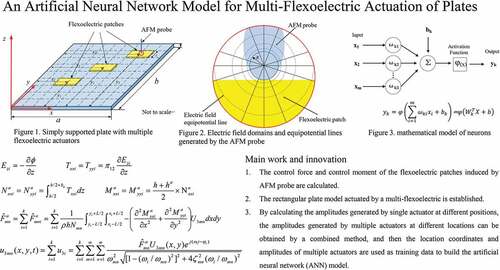
A rectangular plate with multiple flexoelectric actuators is shown in . To simplify the calculation, it is assumed that the geometric dimensions of the flexoelectric patches are the same. Geometric parameters of rectangular plate and flexoelectric patches are shown in , in which, the length, width and thickness of the plate and the length and thickness of the flexoelectric patches are denoted by a, b, h, L and ha respectively. It is assumed that the boundary condition of rectangular plate is simply supported on four sides. shows a schematic diagram of the electric field generated by the AFM probe. R is the AFM probe radius, which affects the electric field gradient. The radius R of the AFM probe tip is far less than the thickness of the patch ha, and the plate h, i.e. R ≪ ha ≪ h. xi and yi are the distances from the center of the flexoelectric patches to the x and y axes.
Figure 1. Simply supported plate with multiple flexoelectric actuators.
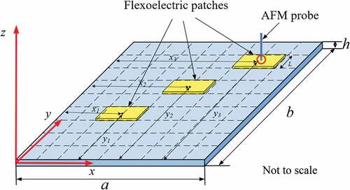
Figure 2. Electric field domains and equipotential lines generated by the AFM probe.
According to the converse flexoelectric effect, when the voltage is applied between the electrode of the flexoelectric patch and the AFM probe, the electric field gradient generated by the AFM probe will produce stress in the flexoelectric patch, which can be used to control the vibration of the plate. When the voltage applied to the probe is , the potential within the flexoelectric patch can be approximated as [Citation32]:
the transverse electric field between the patch and the AFM probe can be expressed as:
with EquationEquation 2(2)
(2) , the induced flexoelectric stress components
and
based on the converse flexoelectric effect and common flexoelectric material matrix can be given:
in which and
are the normal stresses in the x and y directions. The membrane force of the flexoelectric patch can be calculated by integrating the stress through the patch thickness as:
with the membrane force, the bending control moment can be further derived as:
For vibration control of thin plate, if only the transverse displacement is considered, the dynamic equation can be expressed as:
where D is the bending stiffness defined as ; ρ is the mass density of the plate;
and
represent the first- and second-order derivation of the transverse displacement u3 with respect to time t; c is the equivalent damping constant; F3 is the external excitation force in the transverse direction;
and
are the distributed control moment induced by the flexoelectric actuators.
EquationEquation 6(6)
(6) can be solved with the modal expansion method by writing the transverse displacement u3 as the summation of all participating modes []:
where U3mn (x,y) is the modal shape function of the rectangular plate and ηmn is the modal participation factor or the modal coordinate. Both U3mn (x,y) and ηmn depend on the mode numbers m and n in the x and y directions, respectively.
The modal function of a structure depends on its boundary conditions. Therefore, the modal function of rectangular plates with four edges simply supported is defined as:
C is the amplitude constant, which will cancel out in the displacement calculation. The modal participation factor ηmn can be calculated with the consideration of the plate’s dynamic equation, eigenvalue analysis, and orthogonality of modal shape functions as:
Where ζmn is the damping ratio and it is a mode-dependent value; is the (m,n)th modal force, including both external mechanical excitation
and flexoelectric control effect
, and can be expressed as:
In this study, to focus on the vibration control effect caused by flexoelectricity, it is assumed that the external mechanical force F3 is zero. k is the number of actuators and is combined flexoelectric control force resulting from k actuators. By substituting the modal shape function EquationEquation 8
(8)
(8) and the actuation bending moment EquationEquation 5
(5)
(5) induced by each actuator into the modal force expression EquationEquation 11
(11)
(11) , the total k actuation modal force is obtained:
when the excitation is assumed to be harmonic and the frequency is , the modal participation factor can be obtained:
where is the phase angle lagging behind the excitation and can be defined as:
By substituting the modal shape function EquationEquation 8(8)
(8) and the modal participation factor EquationEquation 14
(14)
(14) induced by each actuator into the displacement expression EquationEquation 7
(7)
(7) , the maximal transverse displacement of the plate for each mode is obtained:
Neural network model
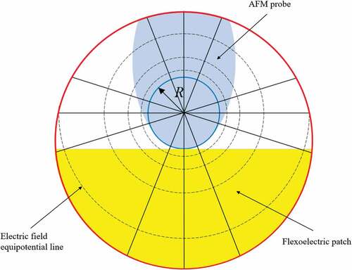
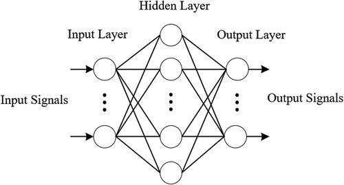
BP (Back Propagation) neural network is a multilayer feedforward neural network, first proposed by Rumelhart et al., 1986. Its main principle is to use the least square method and gradient descent iteration to minimize the root mean square error between the neural network output value and the desired output value, so as to realize the complex nonlinear mapping. The general structure of BP network consists of an input layer and an output layer, and other intermediate parts are called hidden layers. In feedforward neural network, processing units of each layer of neural network are connected with all units of the previous layer. These processing units are called neurons, and their basic structure is shown in . In the , is the weight of each layer network, and
is the threshold. Each input is multiplied with the weight and then added with the threshold, and then the output is obtained through the activation function
. The activation function
. The connections between neurons in a neural network are assigned by weights. These weights are adjusted through the training process to optimize the output of the neural network. BP neural network adjusts weights by δ algorithm. A typical three-layer neural network is shown in .
Figure 3. mathematical model of neurons.
Figure 4. Schematic diagram of neural network model.
The process of BP neural network algorithm is as follows: (1) Randomly define the weight and threshold
of each layer network. (2) Randomly select training data to calculate the input and output of neurons in each layer. (3) Modify the weight of layer network through hidden layer. (4) Calculate the global error. (5) Judge whether the error meets the requirements. When the error reaches the preset accuracy or the number of learning times is greater than the set value, the algorithm is terminated. Otherwise, the next learning sample and the corresponding expected output are selected for the next round of learning.
In this paper, a three-layer feedforward neural network model is established with the position coordinates of the actuator as the input and the maximum amplitude of the elastic plate as the output. This model can accurately predict the vibration caused by multiple actuators at any position. In order to get the best actuator placement position, it is necessary to input as many combinations of actuator positions as possible into the neural network model, and quickly obtain the plate amplitude generated by the actuator at different positions. Then, the position where the plate generates the maximum amplitude is the best position of the actuator.
Case studies
In this section, the first part will discuss the influence of the size, shape (aspect ratio) and thickness of the flexoelectric patch on the flexoelectric actuation effect. The second part will compare the results of the flexoelectric actuation neural network model and the theoretical calculation to verify the accuracy of the neural network model. The third part will evaluate the optimal position of the multi-actuator actuation through the neural network model, and obtain the best flexoelectric actuation effect. The parameters of the elastic plate (polypropylene) and actuator (BST) are listed in .
Table 1. Parameters and properties of the plate model.
The flexoelectricity induced transverse displacement with single actuator
Influence of flexoelectric patch parameters
When the flexoelectric patch is placed in the center of the plate and the same voltage is applied, the size and aspect ratio of the flexoelectric patch are changed, and the displacement at the center of the plate for mode (1,1) is shown in .
Table 2. Actuation results of flexoelectric patches of different sizes.
When changing the shape and area of the flexible spot, the amplitude of the plate center is almost unchanged. The converse flexoelectric effect is caused by the electric field gradient, and the electric field gradient generated by the AFM probe is mainly concentrated in a small area of the probe tip, so the stress induced by the flexoelectric patch is mainly concentrated in the center of the patch. The effect of changing the patch area and aspect ratio on the converse flexoelectric effect is limited. Therefore, in the modeling process of the neural network model, the structural parameters of the flexoelectric patch will be ignored, and other parameters will be selected as input data.
Influence of flexoelectric patch positions
This section discusses the influence of actuator position on flexoelectric actuation. When the excitation of the external mechanical force is not considered, and the position of the flexoelectric patch on the plate is changed, the transverse displacement of a certain point (mode(1,1) at , mode (2,1) at
, mode (2,2) at
, mode (3,1) at
) on the elastic plate caused by the converse flexoelectric effect is shown in .
Figure 5. Induced displacements caused by actuator in different positions.
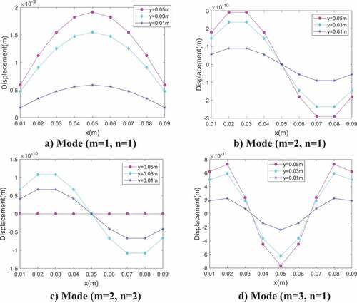
As can be seen, changing the position of the actuator significantly changes the displacement on the plate actuated by the converse flexoelectric effect. The amplitude of the plate induced by the flexoelectric actuator at different positions is related to the mode shape. When the y-direction is the first-order resonance, the actuator can be placed at the position of y = 0.05 m to have a better actuation effect. When the same actuator is in different positions, it is possible to produce opposite displacements at a point on the plate. The actuator will produce different actuation effects at different positions, so there are some optimal positions in each mode to achieve the maximum actuation effect. If the position of the actuator is used as the input and the displacement of the plate is used as the output, a neural network model can be established to predict the flexoelectric actuation and analyze the optimal position of the actuator.
The ANN Model of single flexoelectric actuation
The establishment of the artificial neural network model requires training data. Some points are uniformly selected on the plate, and the amplitude of the plate vibration driven by the actuator at these positions is calculated as the training data. After the neural network model is established through training, the positions of some points are selected from the training data to verify the accuracy of the neural network. These data are not included in the training data. The prediction results for mode (m, n) = (1,1), (2, 1), (2, 2), (3, 1) are shown in .
Table 3. Displacement of theoretical model and neural network model for mode (1,1).
Table 4. Displacement of theoretical model and neural network model for mode (2,1).
Table 5. Displacement of theoretical model and neural network model for mode (2,2).
Table 6. Displacement of theoretical model and neural network model for mode (3,1).
By comparing the results of ANN model and theoretical calculation results, the accuracy of neural network can meet the requirements, and the efficiency of training network is also very high, which usually only takes a few minutes, can save a lot of computing resources and time. From the data in the table, it can be concluded that the neural network model can accurately predict the amplitude of the plate with the flexoelectric actuator. Enter as many positions on the plate as possible into the neural network model, the displacement of the plate induced by the actuator at these positions can be quickly obtained, and the optimal actuator position can be obtained. Change the input to the position coordinates of multiple actuators to establish the neural network model, which can be used to predict the vibration results of the multi-flexoelectric actuation and analyze the optimal actuation position of the multi-flexoelectric actuator.
The ANN model of multi-flexoelectric actuation
An artificial neural network model was established to study the optimal actuation position of multi-flexoelectric actuator. The input of the model is the coordinate (X1,Y1,X2,Y2…Xn,Yn) of the multi-actuator position, and the output is the is the displacement of the maximum value of the mode shape function on the plate.
Prediction results of multi-flexoelectric actuation neural network
First, the accuracy of the neural network models of the two actuators is verified, and the results are shown in . 10 groups of data were randomly selected for verification for each mode, and most of the errors were below 5%. The larger error of individual data was due to the fact that the output value was too small, resulting in a large relative error. Focus only on actuator positions that produce larger displacements, so those results with larger errors have no impact on the study.
Table 7. Displacement of theoretical model and neural network model for mode (1,1).
Table 8. Displacement of theoretical model and neural network model for mode (2,1).
Table 9. Displacement of theoretical model and neural network model for mode (2,2).
Table 10. Displacement of theoretical model and neural network model for mode (3,1).
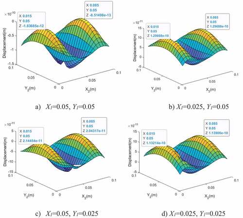
Taking all the positions of the two actuators as input, and the actuators cannot overlap, the neural network model can quickly output the corresponding displacement results. show the displacement results of one actuator in some typical positions changing the position of another actuator for different modes. The blank area in the figure is the position of the first actuator, the second actuator cannot be placed there.
Figure 6. Induced displacement of two actuators for mode (1,1).
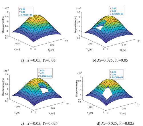
Figure 7. Induced displacement of two actuators for mode (2,1).
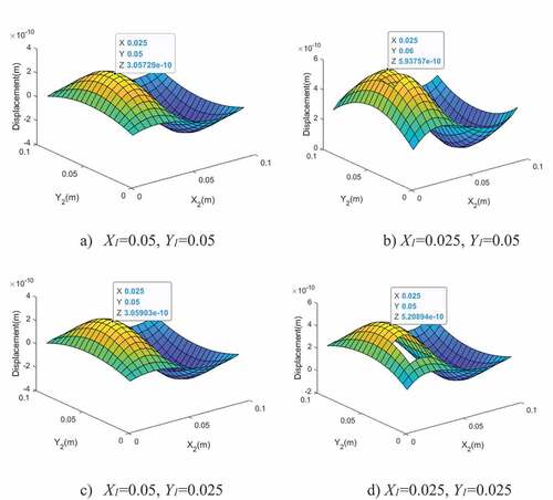
Figure 8. induced displacement of two actuators for mode (2,2).
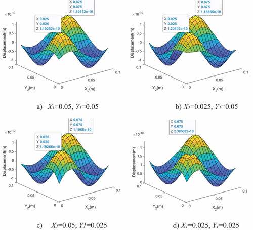
Figure 9. Induced displacement of two actuators for mode (3,1).
The prediction results of the flexoelectric actuation neural network model of the three actuators are shown in . Similar to the two actuators, the neural network model can accurately predict displacement result.
Optimal positions of multi-flexoelectric actuator
The neural network model is able to predict the result quickly and accurately, and the displacement result is obtained by taking the position data of as many actuators as possible as input. The position that can produce the maximum displacement is the best actuator position. lists the optimal positions for two and three actuators for each mode. Due to the symmetry of the structure and boundary conditions, the optimal position is not unique, and the 10 sets of data with the largest displacement predicted by the neural network model are listed.
Table 11. Displacement of theoretical model and neural network model for mode (1,1).
Table 12. Displacement of theoretical model and neural network model for mode (2,1).
Table 13. Displacement of theoretical model and neural network model for mode (2,2).
Table 14. Displacement of theoretical model and neural network model for mode (3,1).
Table 15. Optimal actuator placement positions for mode (1,1).
Table 16. Optimal actuator placement positions for mode (2,1).
Table 17. Optimal actuator placement positions for mode (2,2).
Table 18. Optimal actuator placement positions for mode (3,1).
Table 19. Optimal actuator placement positions for mode (1,1).
Table 20. Optimal actuator placement positions for mode (2,1).
Table 21. Optimal actuator placement positions for mode (2,2).
Table 22. Optimal actuator placement positions for mode (3,1).
From the analysis of the prediction results of the neural network model, the optimal position of the actuator is related to the mode shape. By placing the actuator at the maximum value of the mode shape, the actuator is able to actuate the plate with maximum amplitudes. Increasing the amplitude of the multi-flexoelectric actuation can achieve better vibration control, reducing the applied voltage, and the multi-actuator strategy can also reduce stress concentration.
Conclusions
In this paper, the actuation effect of the converse flexoelectric effect was studied for a rectangular plate model with multiple flexoelectric actuators. The electric field gradient was generated in the flexoelectric material by the AFM probe, which generates stress and bending moment inside the actuator. It was verified that the size and shape of the flexoelectric patch have limited effect on the converse flexoelectric actuation. The influence of the actuator position on the rectangular plate on the flexoelectric actuation was studied, and it was found that the influence of the actuator in different positions on the actuation effect is obvious, and the influence of the position on the actuation in different modes was also different. Therefore, a multi-flexoelectric actuation neural network model is established. It has been verified that the relative error of the predicted data is within 5%, and the data with excessive error has no influence on the research results. The neural network was used to predict the actuation effect of actuators in different positions, and the optimal actuator position can be obtained from the prediction results. By selecting the deformation data of different structures as training data, the flexoelectric actuation neural network models of different structures can be established. The results of the case study show that the neural network can be used to study the multi-actuators actuation problems, can quickly and accurately determine the optimal position of multi-actuators, improve the control effect of the actuators, and can be applied to the study of active vibration control.
Disclosure statement
No potential conflict of interest was reported by the author(s).
References
- Gardner JW, Varadan VK, Awadelkarim OO. Microsensors, MEMS, and smart devices. Hoboken, New Jersey,USA: John Wiley & Sons, Inc; 2003.
- Lin X, Chen H, Ma Y, et al. Investigation of temperature sensitivity of actuation performance for piezoelectric fiber composites. Ceram Int. 2017;43(13):10590–10594.
- O’Driscoll M. Design for manufacture. J Mater Process Technol. 2002;122(2):318–321.
- Schitter G, Stemmer A. Identification and open-loop tracking control of a piezoelectric tube scanner for high-speed scanning-probe microscopy. IEEE Trans Control Syst Technol. 2004;12(3):449–454.
- Wang R, Tang E, Yang G, et al. Experimental research on dynamic response of PZT-5H under impact load. Ceram Int. 2020;46(3):2868–2876.
- Dudek K, Dulski M, Goryczka T, et al. Structural changes of hydroxyapatite coating electrophoretically deposited on NiTi shape memory alloy. Ceram Int. 2018;44(10):11292–11300.
- Tsay C-Y, Lin Y-H, Jen S-U. Magnetic, magnetostrictive, and AC impedance properties of manganese substituted cobalt ferrites. Ceram Int. 2015;41(4):5531–5536.
- Feng F, Yan Y. Large electrostrictive effect in Mn-doped BCZT ferroelectric ceramics. Ceram Int. 2019;45(17, Part A):21315–21320.
- Ma H, Chen B, Qin L, et al. Design and testing of a regenerative magnetorheological actuator for assistive knee braces. Smart Mater Struct. 2017;26(3):035013.
- Oh J-S, Choi S-B. State of the art of medical devices featuring smart electro-rheological and magneto-rheological fluids. J King Saud Univ Sci. 2017;29(4):390–400.
- Catalan G, Sinnamon LJ, Gregg JM. The effect of flexoelectricity on the dielectric properties of inhomogeneously strained ferroelectric thin films. J Phys. 2004;16(13):2253–2264.
- Ma W, Cross LE. Flexoelectricity of barium titanate. Appl Phys Lett. 2006;88(23):232902.
- Zalesskii VG, Rumyantseva ED. Converse flexoelectric effect in the SrTiO3 single crystal. Phys Solid State. 2014;56(7):1352–1354.
- Abdollahi A, Domingo N, Arias I, et al. Converse flexoelectricity yields large piezoresponse force microscopy signals in non-piezoelectric materials. Nat Commun. 2019;10(1):1266.
- Mu F, Zhongmin X, Hornsen T. Distributed multi-flexoelectric actuation and control of plates. AIAA Stud J. 2019;58(3):1377–1385.
- Fu JY, Zhu W, Li N, et al. Experimental studies of the converse flexoelectric effect induced by inhomogeneous electric field in a barium strontium titanate composition. J Appl Phys. 2006;100(2):024112.
- Hu SD, Li H, Tzou HS. Distributed flexoelectric structural sensing: theory and experiment. J Sound Vib. 2015;348:126–136.
- Pal A, Restrepo V, Goswami D, et al. Exploiting mechanical instabilities in soft robotics: control, sensing, and actuation Adv. Mater . 2021;33(19):2006939.
- Wu T, Liu K, Zhang S, et al. An actuation method by a biconcave beam structure with converse flexoelectric effect. Smart Mater Struct. 2019;28(11):115025.
- Hu SD, Li H, Tzou HS, et al., Static nano-control of cantilever beams using the inverse flexoelectric effect, Proceedings of the ASME 2011 International Mechanical Engineering Congress and Exposition. November 11–17, 2011. Denver, Colorado, USA. Volume 7: Dynamic Systems and Control; Mechatronics and Intelligent Machines, Parts A and B ;463–470.
- Mu F, Bolei D, Hornsen T. Multiflexoelectric actuation and control of beams. AIAA Stud J. 2019;57(12):5503–5513.
- Zhang XF, Li HY, Tzou HS. Flexoelectric vibration control of plates by line electrodes, Proceedings of the ASME 2016 International Design Engineering Technical Conferences and Computers and Information in Engineering Conference. August 21–24, 2016. Charlotte, North Carolina, USA. Volume 8: 28th Conference on Mechanical Vibration and Noise. V008T10A056 .
- Ghasemi H, Park HS, Rabczuk T. A level-set based IGA formulation for topology optimization of flexoelectric materials. Comput Methods Appl Mech Eng. 2017;313:239–258.
- Hassoun MH. Fundamentals of artificial neural networks. Proc IEEE. 1996;84(6):906.
- Dave VS, Dutta K. Neural network based models for software effort estimation: a review. Artif Intell Rev. 2014;42(2):295–307.
- Narendra KS, Parthasarathy K. Identification and control of dynamical systems using neural networks. IEEE Trans Neural Networks. 1990;1(1):4–27.
- Song G, Chaudhry V and Batur C. (2003). A Neural Network Inverse Model for a Shape Memory Alloy Wire Actuator. Journal of Intelligent Material Systems and Structures, 14(6), 371–377. 10.1177/1045389X03034628
- Sun C, He W and Hong J. Neural Network Control of a Flexible Robotic Manipulator Using the Lumped Spring-Mass Model. IEEE Trans. Syst. Man Cybern, Syst., 47(8), 1863–1874. 10.1109/TSMC.2016.2562506
- Abdeljaber O, Avci O and Inman D J. (2016). Active vibration control of flexible cantilever plates using piezoelectric materials and artificial neural networks. Journal of Sound and Vibration, 363 33–53. 10.1016/j.jsv.2015.10.029
- Li, H, Li, H, & Tzou, H. ”Neural-Network Vibration Control of Rings With Light-Activated Shape Memory Polymer Actuators.” Proceedings of the ASME 2015 International Design Engineering Technical Conferences and Computers and Information in Engineering Conference. Volume 8: 27th Conference on Mechanical Vibration and Noise. Boston, Massachusetts, USA. August 2–5, 2015. V008T13A006. ASME. https://doi.org/10.1115/DETC2015-47019
- Samaniego E, Anitescu C, Goswami S, et al. An energy approach to the solution of partial differential equations in computational mechanics via machine learning: concepts, implementation and applications. Comput Methods Appl Mech Eng. 2020;362:112790.
- Abplanalp M . Piezoresponse scanning force microscopy of ferroelectric domains (ETH Zürich). 2001. Diss., Naturwissenschaften ETH Zürich, Nr. 14048, 2001.
- Ma W, Cross LEJAPL. Flexoelectric polarization of barium strontium titanate in the paraelectric state, Appl. Phys. Lett. 2002;81:3440–3442.