
 ?Mathematical formulae have been encoded as MathML and are displayed in this HTML version using MathJax in order to improve their display. Uncheck the box to turn MathJax off. This feature requires Javascript. Click on a formula to zoom.
ABSTRACT
Carbon fiber reinforced polymer (CFRP) can be applied for bridge cables due to its excellent properties. As the important load-bearing structural component, real-time force monitoring of the CFRP cable is required. This paper presents a new smart CFRP cable that combines the self-sensing rods with embedded sensors and the anchorage system using extrusion technology. By embedding optical fiber (OF) and coaxial cable Fabry-Perot interferometer (CCFPI) into CFRP rods respectively, two types of self-sensing rods (CFRP-OF rod and CFRP-CCFPI rod) were fabricated. A new anchorage unit using an extrusion process was proposed as a basic component of smart CFRP cables. Anchorage units holding a CFRP-OF rod and a CFRP-CCFPI rod were tested to obtain their sensing and mechanical properties. Three anchorage units were assembled to form a smart CFRP cable with self-sensing functionality. A verification test was carried out to confirm the capability of monitoring the cable force. The test results demonstrate that the smart CFRP cable composed of multiple anchorage units has good potential in bridge engineering.
GRAPHICAL ABSTRACT
Introduction
Carbon fiber reinforced polymer (CFRP) has great potential for cables due to the advantages of light-weight, high strength, corrosion resistance and fatigue resistance [Citation1,Citation2]. The CFRP cables can be used as the primary load-bearing structural components of long-span bridges, including cable-stayed bridges and suspension bridges [Citation3]. In order to ensure the safety of long-span bridges, inspection and health monitoring of the CFRP cables in service are critical [Citation4–6]. Therefore, it is essential to develop a smart CFRP cable with self-sensing function, and the application of the cable can provide a solution to the needs of bridge engineering.
With the advancement of information technology, various smart FRP rods have been developed to monitor the safety status of the key components. Applying the optical fiber Bragg grating (FBG) sensing technology, the smart FRP rod with embedded FBG sensors has been produced to monitor the discrete mechanical behavior along its length [Citation7,Citation8]. Similarly, an optical fiber sensor was mounted into the FRP anchor rod to monitor its full-scale strain [Citation9]. Utilizing the technique of Brillouin Optical Time Domain Analysis (BOTDA), the continuous mechanical behavior was monitored through the OF sensor-based anchor rod. In addition, coaxial cables and optical fibers follow the same electromagnetic(EM) theory [Citation10,Citation11]. Researchers developed GFRP-CCFPI bars by packaging coaxial cable Fabry-Perot interferometer sensors into GFRP bars [Citation12]. The proposed GFRP-CCFPI bar was used to monitor the large strains in the components. The proposed self-sensing rods are lightweight, corrosion resistant and easy to use in structures.
The manufacture of a smart CFRP cable also depends on an efficient anchorage system. In recent years, researchers have proposed a variety of anchorage systems for CFRP cables. Al-Mayah et al. presented a curved-wedge anchorage system for CFRP rod, where the outer surface of the wedge and the inner surface of the barrel were fabricated to be curved for uniform contact pressure [Citation13]. Jiang et al. developed a wedge-bond anchorage system for CFRP tendons with the concept of combining a bonding zone and a clamping zone [Citation14]. Schmidt et al. proposed a new easy-to-install and efficient anchorage system with an integrated sleeve and a differential angle between the barrel and wedge sections [Citation15]. The design concept of these developed anchorage systems is to improve anchorage efficiency.
However, current research has focused on cables made up of steel strands or steel wires [Citation6,Citation16]. The way to construct a smart cable is to replace the steel wires in the cable with the self-sensing rods. With a view to making the self-sensing rods more than just smart components of steel cables, it is necessary to propose a method for the construction of smart cables with CFRP rods. With the possibility of combining different self-sensing rods, the new smart CFRP cable can be used in a variety of applications [Citation17–20].
In this paper, an efficient extruded anchorage system developed in the previous work is used in the new method of constructing cable [Citation21]. Based on the extrusion process, the easy-to-assemble anchorage system is capable of gripping both self-sensing rods and normal rods(without functionality of self-sensing). A new anchorage unit consisting of an extruded anchorage system and five rods (including self-sensing rods) is proposed. Firstly, a self-sensing anchorage unit with two types of self-sensing rods was tested to investigate its sensing performance and mechanical properties. Then, three sets of anchorage units were assembled to fabricate a smart CFRP cable. Finally, the cable force was measured to verify the self-sensing functionality of the cable utilizing the internal anchorage units.
Fabrication and configuration of a smart CFRP cable
Manufacture of self-sensing CFRP rods
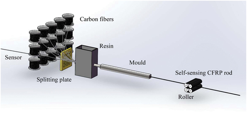
The manufacturing process of the self-sensing CFRP rods is shown in . First, the sensor was inserted through the splitting plate. Then the resin solidified the sensor and the carbon fibers together. Both bare optical fiber and coaxial cable Fabry-Perot interferometer can be used as sensors to fabricate self-sensing CFRP rods. The CFRP rod embedded with optical fiber sensor is referred to as the CFRP-OF rod, and the CFRP rod embedded with CCFPI sensor is referred to as the CFRP-CCFPI rod.
Figure 1. Manufacturing process of the self-sensing CFRP rods.
shows the manufactured CFRP-OF rod and CFRP-CCFPI rod with a diameter of 5.2 mm. Both types of self-sensing rods were extended at both ends for developing the front and back jumpers by fusing additional jacket sensors. Considering the fact that joint might be damaged during application, protective treatment was adopted to prevent external damage.
Figure 2. The configuration of self-sensing CFRP rods.
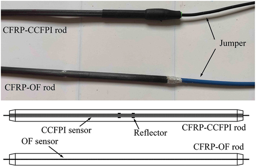
As shown in , the embedded CCFPI sensor comprises a pair of partial EM wave reflectors. As an EM wave travels inside the coaxial cable, two waves are reflected from the reflectors. When two reflected waves encounter each other, an interference signal(U) is generated. The interference signal can be written as:
where Γ(f) is the amplitude coefficient of the reflection, f is the frequency of EM wave, α is the propagation loss coefficient, z represents the coaxial cable direction, τ is the time delay between two reflected waves, t is the time, d is the inter-reflector distance, ∈r is the relative permittivity of the insulator, and c is the speed of light in vacuum.
In the interference spectrum, the resonant frequencies change with the time delay. According to EquationEq. (1)(1)
(1) , the Nth resonant peak(fN) can be deduced:
In general, the applied strain (ε) will cause a change in time delay, and the relationship can be expressed as follows:
where Δd is the change in the distance between two reflectors, Δ∈r is the change in the relative permittivity of the insulator, P eff is the effective Pockels coefficient of the inner dielectric material of the coaxial cable. Therefore, the Nth resonant frequency shift (Δf N) can be deduced as follows:
From EquationEqs.(3)(3)
(3) and (Equation4
(4)
(4) ), the relationship between the applied strain and the resonant frequency shift can be derived as follows:
For the CFRP-OF rod, the axial strains along the rod can be sensed by the built-in OF sensor. Assuming that the cross-coupling effect of strain and temperature can be neglected [Citation22], the Brillouin frequency shift (ΔυB) can be expressed as follows:
where Δε is the applied strain, ΔT is the environmental temperature change, CT and Cε are the temperature and strain sensing coefficients of the OF sensor, respectively.
Based on the same manufacturing process, the resin solidified the steel wires and carbon fibers together to form the CFRP- steel wire rod. As a normal rod (without embedded sensor), the CFRP- steel wire rod was developed for load-bearing. The self-sensing CFRP rods and normal rods were tested to confirm the mechanical properties, the typical stress-strain curves of the rods are shown in the . For rods with a diameter of 5.2 mm, a mechanical anchorage system for anchoring one rod was used in the tests. All rods in the test showed elastic behavior prior to failure. Five specimens of each rod were taken for testing and the average of the test results for each group was recorded. shows the comparison of mechanical properties between the self-sensing rods and the normal rod. It can be seen that the elastic modulus of the normal rod is significantly higher than that of the self-sensing rods.
Figure 3. Stress-strain curves of manufactured rods.
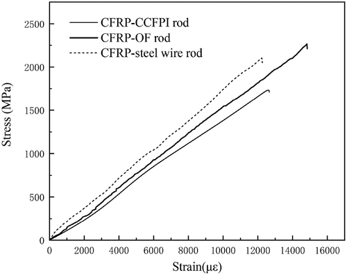
Table 1. Test results of manufactured self-sensing rods and normal rod.
Extrusion process of the anchorage unit
The anchorage unit is designed as a basic component of the smart CFRP cable. The anchorage unit consists of five CFRP rods and an extruded anchorage system. The anchorage unit assembled with the self-sensing rods is referred to as the self-sensing anchorage unit. shows the extruded anchorage system for five CFRP rods and the applicable die used in the extrusion process. The extruded anchorage system includes a steel barrel and an aluminum sleeve, and the applicable die is machined according to the dimensions of the anchorage system. The radial designing parameters of the components satisfy the following:
Figure 4. Extruded anchorage system and the applicable die.
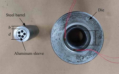
where D is the minimum internal diameter of the die, d is the outer diameter of the aluminum sleeve, b is the minimum thickness of the steel barrel.
The anchorage mechanism is designed to utilize the plastic deformation of the metal during the extrusion process [Citation23,Citation24]. Due to the trapezoidal extrusion region on the outer surface of the steel barrel, the extruded anchorage system can generate a radial gripping force as it passes through the designed die. The anchorage effect on the rods depends on the generated radial gripping force.
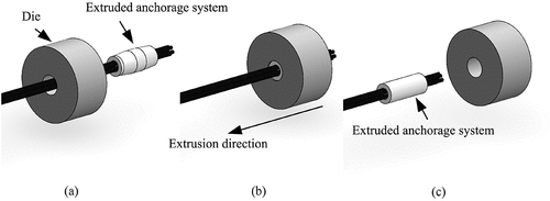
shows the extrusion process of an extruded anchorage system with five CFRP rods. First, five CFRP rods were assembled with the extruded anchorage system. Next, the extruded anchorage system was pushed into the die in the extrusion direction. Finally, the rods were firmly gripped by the extruded anchorage system. The five CFRP rods were made up of normal rods and self-sensing rods. For the self-sensing rods, the ends of the rods were protected during the extrusion process. With the extruded anchorage system installed at both ends of each of the five CFRP rods, an anchorage unit for practical engineering applications was assembled. The calculated parameters of the load carried by the unit can be derived from the configuration of the rods in each anchorage unit. With the assumption that the strains of the rods in the anchorage unit are the same, the force of the unit in service can be calculated as follows:
Figure 5. Extrusion process of anchorage system:(a) assembly; (b) during extrusion; (c) after extrusion.
where Fu is the force of the unit, Ar is the area of the rod, εm is the measured axial strain of the rod and Ei is the elastic modulus of the anchored rod.
Fabrication of the smart CFRP cable
The smart CFRP cable was fabricated by assembling multiple anchorage units together. Different numbers of anchorage units can be assembled to create a cable system with different load-bearing capacities. After determining the outer diameter of the self-sensing rods, different types of sensors can be employed in the manufacture of the smart CFRP cable. shows the configuration of a smart CFRP cable system assembled from three anchorage units. The load-bearing end of the cable includes three metal parts: anchorage plate, adjusting device and load bearing ring.
Figure 6. Configuration of a smart CFRP cable system assembled from three anchorage units.
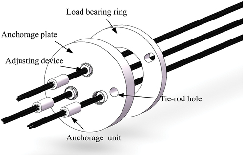
The anchorage plate is the installation base for the anchorage units, and the number of holes in the center section corresponds to the number of the anchorage units required to constitute the cable. Due to the fact that the length of the central part is different for each anchorage unit, an adjustment device with external threads is provided at each hole to control the longitudinal position of the anchorage unit. By turning the adjusting device, all the anchorage units can have a similar preload. In practice, the arrangement of multiple anchorage units may make the cable system in eccentric tension state. In this case, it is necessary to equip the anchorage plate with a load bearing ring for reducing the effect of eccentric tension.
Since the smart CFRP cable is based on the combination of multiple units, the force of the cable is equal to the sum of the forces measured in each unit. After determining the configuration of the used units, the cable force can be calculated as follows:
where Fc is the cable force, Fui is the force of the unit.
Sensing performance of the self-sensing anchorage unit
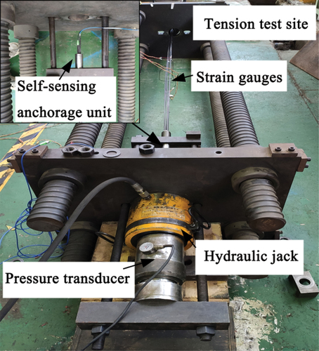
A static tension test was conducted to confirm the sensing performance of the self-sensing anchorage unit. The self-sensing anchorage unit contained a CFRP-OF rod, a CFRP-CCFPI rod and three CFRP-steel wire rods. Two kinds of self-sensing rods were not placed side by side to allow axial strain monitoring without interaction. The tensile test setup of the self-sensing anchorage unit is shown in . The loading end of the test setup was fitted with a hydraulic jack and a pressure transducer. An oil pump was operated to drive the hydraulic jack for applying tension, and a pressure transducer provided a real-time display of the tension. The fixed end of the test setup was provided with an end plate to limit the longitudinal movement of the extruded anchorage system.
Figure 7. Test setup of self-sensing anchorage unit.
Measurements of the CFRP-OF rod were obtained by utilizing the BOTDA interrogating technique, and the CFRP-CCFPI rod was measured using a VNA. The CFRP-OF rod and CFRP-CCFPI rod were connected to the analyzers via the front/back jumpers at the ends. The strain gauges were attached in the middle section along the length of the self-sensing rods. The measured data of strain gauges were recorded by a commercial data acquisition device (DH3816, Donghua Testing Technology Co., LTD).
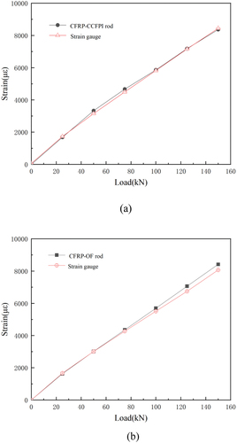
In the test, the hydraulic pump was operated to load the anchorage unit at a rate of 20 kN/min, and the load was gradually increased from 0 kN to 150 kN. The loading process was divided into 6 levels, the load was held at each level for 5 minutes. The measurement of the self-sensing rods took less than 4 minutes, and the strain can be obtained within the duration of the load. shows the comparison of strains measured by self-sensing rods and strain gauges. It can be observed that the measured values of CFRP-OF rod and CFRP-CCFPI rod match those of the strain gauges on the self-sensing CFRP rods, respectively. As the load level gradually increases, the strain of the rods exhibit an approximately linear increase. Both CFRP-OF rod and CFRP-CCFPI rod fit into the self-sensing anchorage unit and provide a good sensing performance in service.
Figure 8. Comparison of strains measured by self-sensing rods and strain gauges: (a) CFRP-CCFPI rod; (b) CFRP-OF rod.
In order to verify the sensing performance of the self-sensing anchorage unit in the ultimate state, two sets of self-sensing anchorage units were continuously loaded to failure. Based on the measurements of CFRP-OF rod and CFRP-CCFPI rod, the stress-strain curves of the self-sensing anchorage unit were obtained, as shown in the . For the specimen 1, the first rod to break occurred when the stress was increased to 1618MPa, and the broken rod was one of the CFRP-steel wire rods. The remaining four rods were reloaded after a stress redistribution. The fracture of the second rod occurred when the load reached 1601 MPa and the broken rod was also a CFRP-steel wire rod. Prior to the fracture of the second CFRP-steel wire rod, the measuring function of the CFRP-OF rod failed without significant fracture. After the failure of the second rod, the stresses in the self-sensing anchorage unit entered the rapidly declining segment and the strains in the declining segment were measured by the CFRP-CCFPI rod. The loading of the self-sensing anchorage unit was stopped at a significant reduction in stress.
Figure 9. Stress-strain curves of self-sensing anchorage unit:(a) specimen 1; (b) specimen 2.
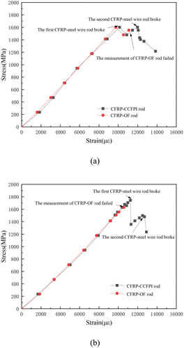
In the case of specimen 2, the strain measurement function of CFRP-OF rod failed without apparent damage after its stress exceeded 1630MPa. The first broken rod of the unit subsequently occurred when the load was increased to 1743 MPa. The rod that first reached the ultimate state was still a CFRP-steel wire rod. After a segment of stress drop, the remaining four rods were reloaded. The second rod broke when the load was again increased to 1498 MPa. The fracture of the second CFRP-steel wire rod resulted in a rapid stress drop. The stress drop section of specimen 2 was also monitored by the CFRP-CCFPI rod.
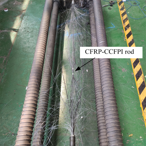
The typical final damage pattern of the self-sensing anchorage unit is shown in , the broken rods present an explosive rupture pattern. It can be found that the CFRP-OF rod and the CFRP-steel wire rods were broken, while the CFRP-CCFPI rod is still intact. From the measured mechanical properties of the rods, it is clear that the CFRP-steel wire rod has the highest modulus of elasticity. Therefore, the CFRP-steel wire rod was subjected to the highest stress level at identical tensile strain, and the ultimate state was reached first in the test. Similarly, the stress level of CFRP-OF rods is higher than that of CFRP-CCFPI rods at the same tensile strain because the former has a higher modulus of elasticity than the latter. For this reason, CFRP-OF rods are more susceptible to damage than CFRP-CCFPI rods in case of a large strain. It is notable that the ultimate strengths exhibited by the CFRP-CCFPI rods in the static tensile tests exceeded those obtained in the mechanical properties tests. This indicates that the extruded anchorage system is more suitable for CFRP-CCFPI rods to reach their ultimate state.
Figure 10. Failure pattern of self-sensing anchorage unit.
The OF sensor is characterized by high accuracy, durability and resistance to electromagnetic interference, and the CCFPI sensor is marked by a large strain measuring range [Citation25,Citation26]. As the OF sensor and the CCFPI sensor are embedded in the CFRP rods, the CFRP-OF rods and CFRP-CCFPI rods have the corresponding sensing performance characteristics. The test results also show that the CFRP-CCFPI rod is more suitable than the CFRP-OF rod for monitoring large strains at the ultimate state. The different sensing characteristics of the rods can be combined for engineering applications.
Validation test of the smart CFRP cable
The smart CFRP cable was constructed by using the self-sensing anchorage unit as the basic component. Three sets of anchorage units were used to fabricate a smart CFRP cable, as shown in . The anchorage unit 1 held a CFRP-CCFPI rod and four steel CFRP-steel wire rods together, and the anchorage unit 2 simultaneously anchored a CFRP-OF rod and four CFRP-steel wire rods. Anchorage unit 1 and anchorage unit 2 were used as self-sensing anchorage units. As the adopted test instruments, a VNA and a BOTDA were connected to anchorage unit 1 and anchorage unit 2, respectively. The five rods of anchorage unit 3 were CFRP-steel wire rods.
Figure 11. Validation test:(a) smart CFRP cable;(b) test setup.
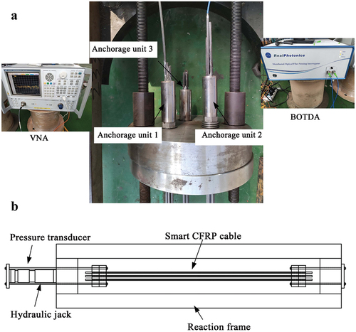
The smart CFRP cable was installed in the tension test setup, as shown in . The two ends of the test setup were defined as the loading end and the fixed end. The anchorage plate and load bearing ring at the loading end were connected to the loading device by two tie rods. The oil pump drove the hydraulic jack to move the tie rods, so that the static stretching of the smart CFRP cable was achieved. During the loading process, a pressure transducer was employed to reflect the variation of tension in real time.
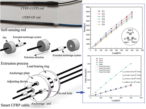
To verify the capability of measuring the cable force in practical applications, a longitudinal tensile test was performed on the smart CFRP cable. The tested cable was loaded from 0 kN to 400 kN at a rate of 20 kN/min. The entire loading process was divided into eight load levels, and the load was held for 5 minutes at each load level. During the load holding, VNA and BOTDA were operated to obtain the measurement results. Two rods from each anchorage unit were measured, and the measurements of six rods(C1 to C6) were recorded in the test. The axial strains of rods C1 and C3 were obtained from the CFRP-CCFPI rod and CFRP-OF rod, and those of rods C2, C4, C5 and C6 were measured by means of strain gauges on the rod surfaces.
shows the strain versus load curves of the rods in the cable. As can be seen from the , the strains measured from the rods all increase nearly linearly as the load level increases. When the measurements of the six rods are compared, the strains of the rods in the three anchorage units increase synchronously with the load. It is also noticeable that there are differences in the strains measured by the six rods under the same load. As the six rods belong to three anchorage units, the anchorage units are subjected to different forces in the cables, which leads to differences in the measured values of the rods in the different anchorage units.
Figure 12. Strain versus load curves of the rods in the cable.
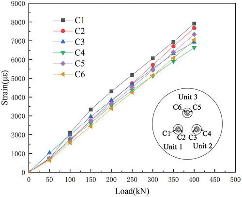
Comparing the measurements from anchorage unit 1 (C1 and C2) and anchorage unit 2 (C3 and C4), it can be found that the measurements from the CFRP-CCFPI rod and CFRP-OF rod are slightly higher than those of the strain gauges on the opposing rods within their respective anchorage units. Different from strain gauges attached to the surface of the rods, the sensors embedded in the self-sensing rods are less affected by the adhesive layer, and thus the self-sensing rods can represent the strain more accurately. Both types of self-sensing anchorage units are suitable for the fabrication of a smart CFRP cable.
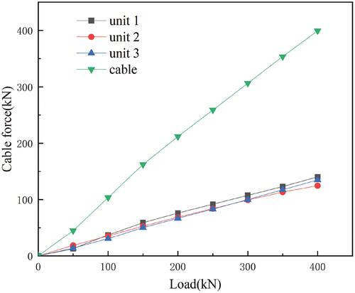
Based on the three sets of strain values collected at each load level, the test results of the three anchorage units and the smart CFRP cable were obtained. The measurements from the CFRP-CCFPI rod and the CFRP-OF rod were adopted for unit 1 and unit 2 respectively. The measured value from the strain gauge on one of the rods was used for unit 3. According to EquationEquation (8)(8)
(8) and EquationEquation (9)
(9)
(9) , the cable force can be calculated from the axial strains obtained from the three units.
shows the measured cable force of the smart CFRP cable at each load level. Due to the different rods contained in the three anchorage units, the forces in the three anchorage units are slightly different at each load level. The measured cable forces based on the three anchorage units are in good agreement with the loads, meaning that the cable force can be calculated accurately using the strain measured by the anchorage units.
Figure 13. The measured cable force of smart CFRP cable.
Compared to traditional CFRP cable assembled directly from rods, the proposed CFRP cable assembled by multi-group anchorage units. Validation tests verify that a new cable consisting of independent and efficient load-bearing units is feasible, the extruded anchorage system of the cable provides high anchorage efficiency. Further, due to the application of anchoring units, various self-sensing rods can be easily applied to the CFRP smart cable and work in synergy with other rods. This new smart CFRP cable can be used as an alternative to the steel cable in actual application of cable structure.
Conclusions
This paper described a method for developing smart cables by combining the self-sensing rods with embedded sensors and an anchorage system using the extrusion process. A novel self-sensing anchorage unit containing two types of self-sensing rods was proposed and tested. In addition, a smart CFRP cable was fabricated through the assembly of three anchorage units. The validation test of the smart CFRP cable was conducted to confirm its ability to measure the cable force. Based on the actual test results, the following conclusions were drawn from this study:
The proposed anchorage unit demonstrated reliable sensing performance and provided results comparable to the strain gauges. In the test, the self-sensing rods and the normal rods were loaded synchronously, while the failure of the measurement performed by the self-sensing rods occurred later than the first cracking of the normal rod. The self-sensing rods embedded with different sensors can work together in a self-sensing anchorage unit, providing more options for the fabrication of a smart CFRP cable.
The proposed smart CFRP cable abandons the traditional method of direct assembly from rods. Instead, the method of assembling multiple individual anchorage units is successfully applied to the manufacture of smart CFRP cables. The validation test of the smart CFRP cable consisting of three anchorage units indicated that the strains of the anchorage units increase simultaneously with the load. The cable force was accurately monitored by calculating the measurement of the anchorage units. With the self-sensing and mechanical property demonstrated in the tests, the proposed smart CFRP cable can meet the requirements of engineering applications.
Acknowledgments
This research was financially supported by the National Natural Science Foundation of China under Grant No. 52178282 and by the Research Funding of the High-Level Talent Project of Hainan Natural Science Foundation under Grant. 2019RC097.
Disclosure statement
No potential conflict of interest was reported by the authors.
Additional information
Funding
References
- Saadatmanesh H, Tannous FE. Relaxation, creep, and fatigue behavior of carbon fiber reinforced plastic tendons. Materials Journal. 1999;96(2):143–153.
- Noisternig JF. Carbon fibre composites as stay cables for bridges. Appl Compos Mater. 2000;7(2–3):139–150.
- Wang L, Zhang J, Xu J, et al. Anchorage systems of CFRP cables in cable structures—A review. Constr Build Mater. 2018;160:82–99.
- Chong KP, Zhu S. Innovative technologies in manufacturing, mechanics and smart civil infrastructure. Int J Smart Nano Mater. 2018;9(4):261–278.
- Ko JM, Ni YQ. Technology developments in structural health monitoring of large-scale bridges. Eng Struct. 2005;27(12):1715–1725.
- Li H, Ou J. The state of the art in structural health monitoring of cable-stayed bridges. Journal of Civil Structural Health Monitoring. 2016;6(1):43–67.
- Yang H, Huang Y, Zhou Z, et al. Long-term performance of packaged fiber Bragg grating sensors for strain monitoring inside creep medium. Int J Smart Nano Mater. 2022;13(1):42–63.
- Li F, Du Y, Sun X, et al. Sensing performance assessment of twisted CFRP with embedded fiber Bragg grating sensors subjected to monotonic and fatigue loading. Sens Actuators A. 2018;271:153–161.
- Huang M, Zhou Z, Huang Y, et al. A distributed self-sensing FRP anchor rod with built-in optical fiber sensor. Measurement. 2013;46(4):1363–1370.
- Huang J, Wang T, Hua L, et al. A coaxial cable Fabry-Perot interferometer for sensing applications. Sensors-Basel. 2013;13(11):15252–15260.
- Wei T, Wu S, Huang J, et al. Coaxial cable Bragg grating. Appl Phys Lett. 2011;99(11):113517.
- Jiao T, Zhou Z, Liu J, et al. Large strain-tolerated smart steel strand with built in coaxial cable Fabry–Perot interferometer. Measurement. 2020;151:107019.
- Al-Mayah A, Soudki K, Plumtree A. Development and assessment of a new CFRP rod–anchor system for prestressed concrete. Appl Compos Mater. 2006;13(5):321–334.
- Jiang T, Fang Z. Experimental investigation on the performance of wedge-bond anchors for CFRP tendons. China Civil Engineering Journal. 2010;43(2):79–87.
- Schmidt JW, Bennitz A, Täljsten B, et al. Development of mechanical anchor for CFRP tendons using integrated sleeve. J Compos Constr. 2010;14(4):397–405.
- Li H, Li D, Song G. Recent applications of fiber optic sensors to health monitoring in civil engineering. Eng Struct. 2004;26(11):1647–1657.
- Xuebing Z, Li W, Tang S, et al. Investigations on the shearing performance of ballastless CRTS II slab based on quasi-distributed optical fiber sensing. Opt Fiber Technol. 2023;75:103129.
- Min R, Liu Z, Pereira L, et al. Optical fiber sensing for marine environment and marine structural health monitoring: a review. Optics & Laser Technology. 2021;140:107082.
- Wang H, Xiang P, Jiang L. Optical fiber sensing technology for full-scale condition monitoring of pavement layers. Road Mater Pavement. 2020;21(5):1258–1273.
- Han J, Pan J, Ma X, et al. Sensing performance of engineered cementitious composites in different application forms. Constr Build Mater. 2022;355:129223.
- Lian S, Jinping O, Zhi Z. Development of a new anchorage system for carbon fiber–reinforced polymer rods using extrusion process. Adv Struct Eng. 2022;25(5):1002–1014.
- Wang H, Xiang P, Jiang L. Strain transfer theory of industrialized optical fiber-based sensors in civil engineering: a review on measurement accuracy, design and calibration. Sens Actuators A. 2019;285:414–426.
- Khosravifard A, Ebrahimi R. Investigation of parameters affecting interface strength in Al/Cu clad bimetal rod extrusion process. Mater Design. 2010;31(1):493–499.
- Fan X, Chen L, Chen G, et al. Joining of 1060/6063 aluminum alloys based on porthole die extrusion process. J Mater Process Tech. 2017;250:65–72.
- Huang J, Wei T, Lan X, et al. Coaxial cable Bragg grating sensors for large strain measurement with high accuracy. Spie. 2012;8345:840–848.
- Moyo P, Brownjohn J, Suresh R, et al. Development of fiber Bragg grating sensors for monitoring civil infrastructure. Eng Struct. 2005;27(12):1828–1834.