
 ?Mathematical formulae have been encoded as MathML and are displayed in this HTML version using MathJax in order to improve their display. Uncheck the box to turn MathJax off. This feature requires Javascript. Click on a formula to zoom.
ABSTRACT
Soft pneumatic robotic grippers have found extensive applications across various engineering domains, which prompts active research due to their splendid compliance, high flexibility, and safe human-robot interaction over conventional stiff counterparts. Previously simplified rod-based models principally focused on clarifying overall large deformation and bending postures of soft grippers from static or quasi-static perspectives, whereas it is challenging to elaborate grasping characteristics of soft grippers without considering contact interaction and nonlinear large deformation behaviors. To address this, based on absolute nodal coordinate formulation (ANCF), comprehensively allowing for structural complexity, geometric, material and boundary nonlinearities, and incorporating Coulomb’ friction law with a multiple-point contact method, we put forward an effective nonlinear dynamic modeling approach for exploring grasping capability of soft gripper. Moreover, we solved the established dynamic equations using Generalized-α scheme, and conducted thorough numerical simulation analysis on a three-jaw soft pneumatic gripper (SPG) in terms of grasping configurations, displacements and contact forces. The proposed dynamic approach can accurately both describe complicated deformed configurations along with stress distribution and provide a feasible solution to simulate grasping targets, whose effectiveness and precision were analyzed theoretically and verified experimentally, which may shed new light on devising and optimizing other multifunctional SPGs.
GRAPHICAL ABSTRACT
1. Introduction
The advancement of soft materials such as silicone, hydrogel, electroactive polymer, shape memory alloy and ionic polymer metal composite [Citation1–3], has significantly accelerated the development of diverse soft grippers which have huge application value in all walks of life. Over the past two decades, soft pneumatic grippers (SPGs) are increasingly gaining attention owing to their merits of excellent flexibility, large deformation, strong robustness, high safety and good environmental compatibility [Citation4]. The design, materials and control of SPGs generally follow a certain basic standard, and completely compliant soft grippers composed of embedded pneumatic networks in soft materials are usually actuated by compressed air. Application of air pressures to chambers of soft grippers induces shape changes accordingly and generates diverse deformation styles including stretching, contracting, bending, twisting, curling, twining, and combinations thereof [Citation5, Citation6]. Consequently, SPGs can achieve not only simple 2D motion but also complex 3D motion, enabling dexterous actions for grasping flexible and fragile objects with variable sizes or irregular shapes in a non-damaging manner.
Currently, a wide variety of investigations have primarily concentrated on the design, fabrication, and grasping experiments of different SPGs tailored for some specific tasks. Representative examples include a starfish-like SPG [Citation7], an octopus-shaped tentacle [Citation8], a five-finger anthropomorphic SPG [Citation9], a four-finger SPG [Citation10–12], a three-finger SPG [Citation13], and other SPGs [Citation14–18]. However, how to model and simulate grasping motion of these SPGs remain a topic worthy of exploration.
To date, numerous research works have addressed static or kinematic modeling and simulation analysis of SPGs. Zhou et al. [Citation19] analyzed three different point contact grasping modes of soft hands, and constructed a static model to study the intrinsic curvature profile and grasping stability. Payrebrune and O’Reilly [Citation20] developed a rod-based model with five-parameter constitutive relation for soft robotic arms to predict their bending deformation postures, and explored intrinsic curvature-pressure and moment-curvature relations through a comparison of finite element model. Uppalapati and Krishnan [Citation21] proposed a pure helical model and a spatial Cosserat rod model for a spiral SPG to capture its deformed behaviors and motion characteristics. Hao et al. [Citation22] built a mathematical model that captures the relationship between geometrical properties of chambers and applied pressures to depict bending deformation of a soft gripper, and analyzed the bidirectional bending extent through quasi-static nonlinear simulation. Gong et al. [Citation23] established a kinematic model for a soft robotic arm with 3D movement based on homogeneous transformation matrices, and predicted its location and motion through mathematical modeling. Wu et al. [Citation24] developed a static model, performed kinematic analysis on a SPG with a jointed endoskeleton structure and revealed a quasi-linear relation between grasping force and input pressure. Based on minimum potential energy method and continuum rod theory, Gu et al. [Citation25] exploited an analytical model for a bionic helical SPG to inspect the influences of geometric parameters, material properties and external force on 3D deformations. Lotfiani et al. [Citation26] presented an analytical model to predict bending, contact force, twist angle of a SPG, and validated the accuracy of theoretical model through finite element simulations and experiments. Besides, there are also lots of relevant investigations on modeling and motion simulation of SPGs [Citation27–29], which will not be listed out here.
To sum up, most previous investigations on SPGs almost focused on design, fabrication, quasi-static or static modeling, simulation analysis, and grasping experiments. However, some studies approximately treated soft grippers as conventional multi-segment rigid rods, and employed Lagrangian method for dynamic modeling and analysis, but it is difficult to establish accurate models and reveal grasping performance and nonlinear dynamic response [Citation24, Citation30, Citation31]. Moreover, there is a scarcity of research on dynamic modeling of SPGs considering contact interaction and nonlinear large deformation. There are also limited in-depth discussions on which methods to be adopted to build an effective dynamic model for SPGs, which is a challenging problem that needs to be addressed urgently. Building on our prior research [Citation32], where we proposed a multiple-point contact method based on absolute nodal coordinate formulation (ANCF) for analyzing a soft pneumatic actuator with nonlinear large deformation, and validated its effectiveness and accuracy. This paper extends our investigation to propose a nonlinear dynamic modeling approach for a specific three-jaw SPG and study its grasping capabilities.
In this paper, within the framework of ANCF, uniting a multiple-point contact method with Coulomb’s friction law, an accurate dynamic model is established to analyze the grasping characteristics of the three-jaw SPG. This paper is organized as follows: Section 2 sets forth overall structural design of the SPG. Section 3 deduces different nonlinear force vectors and their derivatives, and builds the corresponding dynamic model. Section 4 implements dynamic simulation analysis and experimental investigation on grasping process of the SPG, clarifies its nonlinear deformation, configuration variations, stress distributions, and then compares theoretical results with experimental ones to verify the validity and precision of the proposed dynamic formulation. Section 5 draws several conclusions and looks ahead to potential applications. This work aims to contribute to a deeper understanding of SPGs’ grasping behavior and facilitate their application in practical engineering.
2. The structural design of a three-jaw SPG
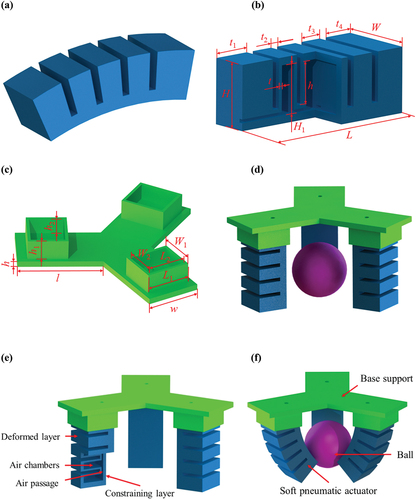
In daily life, numerous objects, such as balloons, lifebuoy, rubber boats, and trampolines, are composed of inflatable and deformable soft materials [Citation33]. Leveraging the principle of inflatable deformation, combining a stable tripod structure with pneumatic networks actuators, we devise a three-jaw soft pneumatic gripper (SPG) which comprises of one base and three soft pneumatic actuators (embedded pneumatic networks in silicone elastomers) positioned at 120° to each other, and three actuators are inserted into three symmetrical rectangular holes in the base according to positional pairing relationship. The bending deformation extent of the SPG in 3D space can be attained by adjusting the magnitude of the air pressure. illustrates the detailed construction of the SPG. Referring to literature [Citation34], and the detailed fabrication process is as follows:
Figure 1. The structural design of a three-jaw SPG. (a) a soft pneumatic bending actuator after inflation, (b) sectional view of the actuator, (c) a base, (d) the SPG and a ball in a still state, (e) the construction and components of the SPG, (f) the SPG and the ball in grasping state.
Step 1: Use Dragon Skin 30 silicone material, mix the two components A and B in a 1:1 volume ratio, and then quickly and evenly stir them in a blender;
Step 2: Apply vaseline evenly on the surface of the upper mold to facilitate subsequent demolding;
Step 3: Evenly inject the prepared silicone material into the upper mold, after the silicone is fully precipitated and filled into the upper mold, remove excess silicone, and use a vacuum pump to vacuum the upper mold filled with silicone for 5 minutes to remove air bubbles;
Step 4: Dry the upper mold filled with silicone at room temperature for 12 hours, then slowly remove the upper mold to obtain the upper air chamber;
Step 5: Drill a hole on the left end face of the upper air chamber, insert the PVC hose into the hole, and seal the interface with silicone adhesive;
Step 6: Evenly inject the prepared silicone material into the lower mold, after vacuuming for 5 minutes, place the upper air chamber on the bottom mold filled with silicone, dry at room temperature for 6 hours, and remove the mold to obtain a soft pneumatic actuator;
Step 7: Check the air tightness, put the soft pneumatic actuator into the water, use the air pump to inflate it slowly, observe whether there are air bubbles escaping;
Step 8: Insert three identical soft pneumatic actuators into a 3D printed base according to corresponding positional relationship to obtain a three-jaw soft pneumatic gripper.
Table 1. Description of specific parameters of the three-jaw SPG.
When air pressure is applied to air chambers of the soft pneumatic actuator through an air passage, expansion deformation occurs. Upon reaching a certain extent, adjacent chambers come into contact to deform the soft actuator. The constraining layer restricts the axial elongation of the actuator’s plane side, and the axial elongation of air chambers becomes a dominant factor which causes the actuator to bend inward. Synchronously applying air pressure to three soft actuators enables the SPG to perform bending actions, resembling human’s fingers for grasping objects of various shapes (e.g. small ball, glass, sea cucumber). The SPG is naturally in a still state, and closed state under positive pressure. This paper mainly focuses on nonlinear grasping characteristics of the SPG and contact interaction between the SPG and target objects. lists specific parameters of the three-jaw SPG in .
3. Deduction of different force vectors and dynamic modeling
3.1. The element elastic force vector and its derivative
While the previously proposed simplified rod-based model is generally useful for describing global bending deformation and postures of soft grippers, it falls short in revealing nonlinear contact characteristics and grasping behaviors between grippers and target objects. To address this limitation, we present a dynamic modeling approach by combining the hyperelastic constitutive Yeoh model with ANCF solid elements [Citation35]. This approach can be extended to explore grasping mechanisms of complex soft grippers. Next, we will describe nonlinear modeling process and derive several different force vectors detailedly.
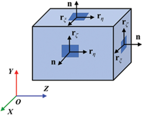
Based on a general theory of flexible bodies [Citation36, Citation37], uniting eight-node ANCF hexahedron solid elements with the selective reduced integration technique to relieve volumetric locking problem of soft bodies [Citation38]. Under this circumstances, ANCF solid elements can accurately capture soft grippers' large bending deformation.
The absolute position coordinate vector of an arbitrary point in an ANCF solid element in Cartesian coordinate system can be expressed as
where is an element shape function matrix, I3 is a 3 × 3 identity matrix,
is a parameterized coordinate vector defined in a natural coordinate system, and
,
,
.
is time-dependent nodal position coordinate vector of the ANCF solid element. Based on a generalized form of the shape functions for the solid element, the specific shape function is formulated as
The transformation relationship between the derivatives of the shape functions with respect to Cartesian coordinate and natural coordinate is denoted as
where is Jacobian matrix and written as
By introducing the volumetric energy penalty function [Citation39], the total strain energy of Yeoh model for hyperelastic incompressible soft elastomers is deduced as
Here, is the determinant of the deformation gradient tensor
at the center point C of the ANCF solid element, which is signified as
.
is the trace of the right Cauchy-Green deformation tensor
, and
is an incompressibility constant which shall be selected adequately large to conform with incompressibility condition
. Three material constants Ci0 (i = 1, 2, 3) can be determined by uniaxial tensile test [Citation39].
Differentiating EquationEquation (5)(5)
(5) relative to the element position coordinate vector
, an element elastic force vector is given by
and derived as
Differentiating the element elastic force vector relative to the element absolute coordinate vector
, and thus the corresponding derivative is expressed as
3.2. The element pressure force vector and its derivative
In this paper, we assume that the air chamber is a cuboid, displays the surface element of air chamber walls.
Figure 2. The surface element of air chamber walls.
The virtual work done by an element pressure force is indicated as
Here, is an element pressure force vector and represented as
Here, p is the value of air pressure, is a position coordinate vector of an arbitrary point on the air chamber wall in the global coordinate system, which is given by
, and
is the shape function matrix of a rectangular surface element subjected to air pressure. In this context, I2 is a 2 × 2 identity matrix. Moreover,
,
, A are severally an element position coordinate vector, a unit normal vector, a surface area of the rectangular surface element, and
is the normal vector of the deformed curved surface.
Differentiating the element pressure force vector relative to the element position coordinate vector
, and the derivative of
is denoted as
3.3. The element gravitational and concentrated vectors and their derivatives
Similarly, the virtual work done by the element gravitational force is written as
Substituting EquationEquation (1)(1)
(1) into EquationEquation (11)
(11)
(11) , the element gravitational force vector has the following expression
Then, the virtual work done by the element concentrated force is given by
Substituting EquationEquation (1)(1)
(1) into EquationEquation (13)
(13)
(13) , the element concentrated force vector takes the following form
Here, g and are the gravitational acceleration vector and the motion acceleration vector of the SPG, respectively. Since the element gravitational force vector
and the element concentrated force
are constant, the derivatives
,
of
,
relative to the element absolute coordinate vector
are both equal to 0. Thus, the derivatives
and
after assembling also equal to 0.
3.4. The element contact force vector and its derivative
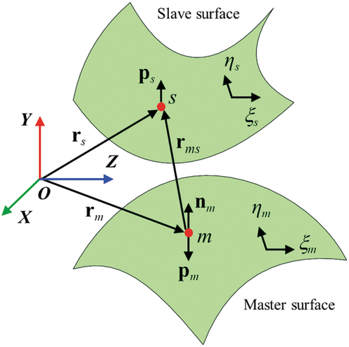
The previously developed multiple-point contact method, in which multiple Gaussian points of a slave element contact with projection points of a master element, is adopted to gain contact forces [Citation32]. The contact zone is approximated as a group of integration points which project onto the corresponding master element. displays the closest point projection in three-dimensional coordinate system. s is a slave point on a slave surface, and m is a master point on a master surface which is the projection point from the slave point s onto the master surface [Citation40]. is the global position vector of the slave point s,
is the global position vector of the master point m. Defining
as the relative position vector of the slave point s relative to the master point m. The closest point projection procedure [Citation41] induces a following minimum problem.
Figure 3. Closet point projection procedure.
is defined as the dot product of the relative position vector
and the corresponding normal vector
, that is,
. It is obvious that for
, the slave point s does not penetrate into the master surface, meaning there is no contact. As for
, it is determined that the slave point s penetrates into the master surface, indicating that penetration has occurred. The value of penetration is
, and the normal contact force per unit area is formulated as
where is the normal contact stiffness per unit area. Base on the penalty function method, the normal contact tractions acting on an arbitrary point of the slave surface and the corresponding projection point of master surface take the form
The position variation of the slave point s and the master point m are given by
Here, are severally the shape function matrices of the slave and master elements of the contact pair, and
severally signify the element position coordinate vectors of the slave and master elements.
The virtual work done by the normal contact tractions vectors is expressed as
Substituting EquationEquation (17)(17)
(17) and EquationEquation (18)
(18)
(18) into EquationEquation (19)
(19)
(19) , the virtual work is rephrased as
where the element contact force vectors of the slave and master elements are represented as
Differentiating the element contact force vectors relative to the corresponding element position coordinate vectors
, and thus the derivatives of the element contact force vectors are severally denoted as
3.5. The element frictional force vector and its derivative
displays the configuration of a contact pair with frictional contact. s is a slave point in a slave surface, and m is the corresponding projection point from the slave point s onto the master surface. is the unit normal vector of the contact surface at the projection point m,
is the global position vector of the slave point s, and
is the global position vector of the projection point m.
Figure 4. The contact pair. (a) Configuration of contact pair with frictional contact, (b) Tangential slipping of the projection point m on the master surface.
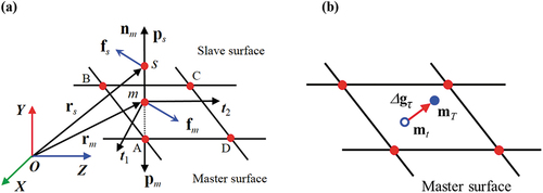
displays the tangential slipping of the projection point m on the master surface. The tangential frictional force can be gained by computing the tangential slipping displacement Δgτ of the projection point m on the master surface [Citation41]. Assume that mt and mT are severally the projection points on the master surface at the current moment t and the latter moment t+Δt. The tangential slipping displacement Δgτ can be indicated as
Define the frictional force vector per unit area acting on the slave point s as . On the basis of the above derivation process, it is known from Coulomb’ friction law that if the norm
is less than or equal to the maximum static frictional force
, where
is the static frictional coefficient and
is the value of penetration, there is no relative slipping between contact interfaces in the tangential direction, and the contact pair is in the stick phase. Inversely, if the norm
is greater than the maximum static frictional force
, there is relative slipping between contact interfaces, and the contact pair is in the slip phase, and the magnitude of the frictional force is proportional to the normal contact force and its direction is opposite to the direction of the relative velocity.
In the stick phase, the variation of is proportional to the displacement variation
of the projection point m from the current moment t to the latter moment t+Δt, and their directions are opposite, which is expressed as
where kτ is the tangential contact stiffness per unit area.
Defining and
as the frictional force vectors per unit area acting on the slave point s at the latter moment t+Δt and the current moment t, respectively. The tangential component of
at the current moment t is
,
is the normal component of
and given by
, and the relationship between
and
is written as
From EquationEquation (25)(25)
(25) , the tangential frictional force vector per unit area acting on the slave point s is represented as
where μd is the dynamic frictional coefficient.
Based on the relationship between action force and reaction force, and the frictional force vector per unit area acting on the projection point m is denoted as
The virtual work done by the element frictional force vectors takes the form
According to , substituting EquationEquation (26)
(26)
(26) and EquationEquation (27)
(27)
(27) into EquationEquation (28)
(28)
(28) , and the virtual work is rephrased as
where the element tangential frictional force vectors of the slave and master elements are formulated as
Differentiating the element tangential frictional force vectors relative to the element position coordinate vectors
, and thus the derivatives of the corresponding element tangential frictional force vectors are severally indicated as
Based on the above derivation, as for the three-jaw SPG in grasping state shown in , and the corresponding dynamic equation can be formulated as
where is the global mass matrix,
is the constraint equation for the SPG subjected to a fixed end constraint, and λ is the Lagrangian multiplier vector corresponding to
.
is the displacement constraint equation for the contact point between the SPG and the ball, and
is the Lagrangian multiplier vector corresponding to
.
,
,
,
,
,
severally refer to the concentrated force vector exerted on the center point of the base, the global generalized elastic force vector, pressure force vector, gravitational force vector, contact force vector and frictional force vector, which can be obtained through an assembling process from the corresponding elemental matrices or vectors and expressed as
where is the mass density, V is the volume of the ANCF solid element in original state,
is the constant symmetric element mass matrix.
is the element elastic force vector,
is the element pressure force vector,
is the element gravitational force vector,
is the element concentrated force vector,
are the element contact force vectors of the slave and master surfaces, respectively,
are the element tangential frictional force vectors of the slave and master surfaces, respectively. In addition,
,
,
,
are the corresponding Boolean matrices, and nk is the number of the solid element, np is the number of the element subjected to air pressure, nc is the number of the contact pairs.
Gaussian quadrature integration technique is employed to calculate the aforesaid different element force vectors and their derivatives [Citation32, Citation42]. The nonlinear dynamic EquationEquation (32)(32)
(32) can be solved by uniting Generalized-α scheme [Citation43] with Newton-Raphson iteration approach [Citation44], and the time step is set as Δt = 10−4 s to guarantee convergence during the calculation process. The (k +1)th step and the (k)th step have undermentioned relation in iterative numerical calculation.
where
The iterative calculation process terminates when the norm of is less than a sufficiently small positive quantity, that is,
, where
is the error tolerance set as
= 10−6.
Moreover, von Mises stress distributions during grasping process of the SPG can be obtained by solving the following EquationEquations (37)(37)
(37) and (Equation38
(38)
(38) )
where ,
,
are severally first, second, and third principal stresses, and
,
,
are shear stresses.
4. Simulation analysis and experimental investigation
4.1. Simulation and experimental study of a single soft pneumatic actuator
First, we perform simulations and experimental studies on a single soft pneumatic actuator at 35 kPa pressure to verify the accuracy of the proposed model, and the theoretical results can be obtained by solving EquationEquation (32)(32)
(32) , (Equation37
(37)
(37) ) and (Equation38
(38)
(38) ). As it is not easy to experimentally measure stress distribution of the soft actuator, and thus finite element simulations are carried out in ABAQUS software to validate stress distribution. Besides, we also conduct experiments on the soft actuator to further clarify the model’s accuracy. The final results are shown in .
Figure 5. Simulations and experiments of a single soft pneumatic actuator. (a) The proposed model’s result, (b) ABAQUS result, (c) the experimental result, (d) Comparative results.
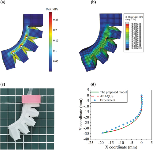
From the color bars in , it can be clearly known that the stresses essentially concentrate in the contact air chamber walls and root areas of adjacent two chambers, and the magnitude of both values is basically the same. Moreover, from the perspective of the deformed configurations, it can be seen from that the proposed model’s result, ABAQUS result and experimental result are basically consistent. Therefore, the model’s accuracy is validated.
4.2. Simulation analysis of the three-jaw SPG
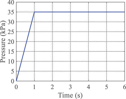
After verifying the proposed model’s accuracy, and then the three-jaw SPG is simulated and analyzed. At the beginning, a small ball is stationary on a support platform, the three-jaw SPG is uninflated, and there is no contact interaction between the SPG and the ball. Then, the SPG is inflated uniformly until the air pressure is equal to 35 kPa at t = 1 s, and the pressure always remain unchanged, and the load curve is shown in . The pressure should be neither too large nor too small, if it is too large, it is possible to burst the air chamber walls. On the contrary, if it is too small, the bending deformation is too small to provide a sufficient grasping force, and the force roughly reaches an appropriate state when the magnitude of the pressure is around 35 kPa. At the moment t = 2 s, the ball falls freely when the gripper grasps the ball. Then, a concentrated force (i.e. 1 N) and an initial velocity (i.e. 24 mm/s) are exerted on the entire structure at the moment t = 3 s.
Figure 6. The applied pressure load.
The detailed parameters of the SPG are listed in . The material parameters of the Yeoh model are C10 = 0.2712 MPa, C20 = 0.03053 MPa, C30 = −0.0004013 MPa, and the incompressibility constant K = 1000 Mpa, the normal and tangential contact stiffness are set as kn = kτ = 4 N/mm3 [Citation32, Citation39, Citation45]. The static and dynamic frictional coefficients between the SPG and the ball are set as μs = 0.4 and μd = 0.3, respectively. The radius and density of the ball are severally r = 20 mm and ρ = 1100 kg/m3.
Herein, neglecting viscous effect between the SPG and the ball, we only consider the contact interaction between both of them, combine a multiple-point contact method based on ANCF [Citation32, Citation46] with Coulomb’s friction law [Citation47], mesh the SPG and the ball at intervals of 1 mm, and then conduct simulation analysis on whole motion process of the soft gripper grasping the ball through numerical solution of EquationEquation (32)(32)
(32) .
shows the configurations and von Mises stress distribution of the SPG and displacement variation of the ball at different moments obtained by solving EquationEquations (32)(32)
(32) , (Equation37
(37)
(37) ) and (Equation38
(38)
(38) ), which reflects the deformation, stress and displacement of the SPG in the process of grasping. At the incipient moment t = 0.0 s, the uninflated SPG hangs down naturally, and the small ball is at rest on the platform ( (a)). As the SPG is gradually inflated, and it starts to contact with the ball at t = 0.7 s, the deformation and stress of adjacent two chambers increasingly grow large until t = 3.0 s ( (b)–(c)), and the ball drops freely down under the action of gravitational force at the moment t = 2.0 s, whereas the overall configuration and stress distribution hardly change before t = 3.0 s. Subsequently, the pressure remains constant (i.e. p = 35 kPa) to hold the ball, and then the concentrated force 1 N is applied to the overall structure, and the SPG can lift up the ball at a constant velocity of 24 mm/s. From t = 3.0 s to t = 6.0 s, under the combined action of the air pressure and the concentrated force, the structure moves upwards by a displacement of about 70 mm ( (c)–(f)). Since the air pressure keeps constant, the stress distribution state remains basically unchanged, and only the displacement varies.
Figure 7. The configurations and von Mises stress of the SPG and displacement variations of the ball at different moments. (a) t = 0.0 s, (b) t = 0.7 s, (c) t = 3.0 s, (d) t = 4.0 s, (e) t = 5.0 s, (f) t = 6.0 s.
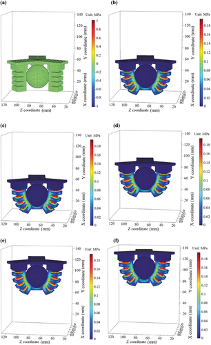
One can easily observe from that the global stress of the undeformed entire structure is zero at initial resting state. From t = 0.7 s to t = 6.0 s, it is evident from color bars that the stresses in the contact areas and the root areas of adjacent two chambers reach the peak value, whereas the values in other areas are relatively small.
Calculation and analysis of the stress variations in these areas will facilitate the optimal design of the SPG without destroying air chambers. It is worth noting that the stresses of the base and the ball are kept at zero all the time during the grasping process, the reason is that both are completely hard bodies, they do not deform their shapes and remain unchanged. On one hand, the overall configuration of the SPG varies with time before the air pressure reaches a maximum value of 35 kPa (i.e. before t = 1.0 s). After that, it almost remains unchanged, the SPG can tightly grasp the ball and lift it to a certain height. On the other hand, the overall configuration variations and stress distribution as well as stress concentration phenomenon can offer us a distinct and straightforward view for exploring the grasping capability of the SPG, which discloses its nonlinear deformation and grasping behaviors under a certain condition.
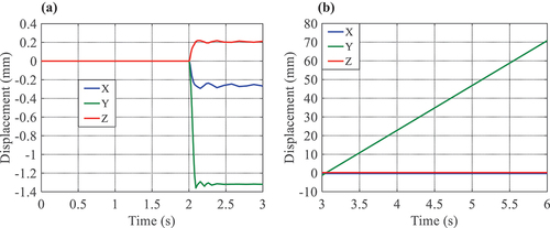
In addition, to reveal the motion process and kinematic characteristics of grasping the ball, we carry out further study on the displacement and contact force variations of the ball. shows the displacement of the ball in two time periods, it can be observed that the ball is still on the support platform before t = 2.0 s, with the displacements remaining zero in three directions. Subsequently, it falls at t = 2.0 s under the action of the gravitational force. The displacement in the vertical direction (i.e. Y direction) sharply drops by about 1.3 mm in a very short time, and the ones in other two directions (i.e. X and Z directions) only fluctuate within about 0.2 mm due to frictional contact and then basically maintain constant. Starting from the moment t = 3.0 s, the displacement in Y direction varies linearly with time and reaches around 70 mm until t = 6.0 s. Meanwhile, the displacements in X and Z directions remain unchanged, and the reason lies in the fact that the applied concentrated force is equal to the sum of the gravitational forces of the SPG and the ball, which causes the entire structure to uniformly move upwards at a given initial velocity of 24 mm/s. The kinematic behaviors can be expounded in terms of displacement changes.
Figure 8. The displacement versus time of the ball in two time periods. (a) t = 0.0 s ~ 3.0 s, (b) t = 3.0 s ~ 6.0 s.
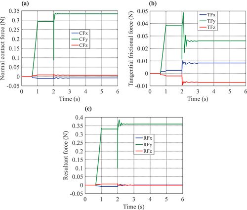
To elucidate the essence of the ball movement during grasping process, we analyze different forces exerted on the ball. exhibits different force variations on the ball grasped by the SPG, and it can be found that the normal contact force, tangential frictional force, and resultant force exerted on the ball along Y direction increase linearly from t = 0.7 s to t = 1.0 s when the SPG begins to be inflated and contact with the ball, and then maintain constant until t = 2.0 s. Followed by, they descend drastically at t = 2.0 s due to the ball’s free-falling motion, and instantly return to a certain value, which is induced by the fact that the gravitational force of the ball is slightly greater than the grasping force generated by the air pressure at the instant of t = 2.0 s, and the grasping force immediately exceeds self-weight of the ball after that instant. This phenomenon leads to a certain degree of relaxation of the grasping force. However, the constant air pressure rapidly restores the grasping force to one certain value and fluctuate in a small range. One can also observe from (a)–(b) that the normal contact force in Y direction dominates and is much greater than the tangential frictional force, and the forces in other two directions only vary in a very small scope before t = 3.0 s and remain constant after t = 3.0 s.
Figure 9. The ball subject to diverse forces. (a) Normal contact force, (b) Tangential frictional force, (c) Resultant force.
It can be known from the above comparative analysis that although the classical FEM can also characterize the bending deformation of the SPG, the proposed method can both clearly illustrate detailed configurations of the SPG and accurately describe its displacement and contact force variations at each moment from a dynamic perspective.
Defining GSPG, GB, FC as the gravitational force of the SPG, the gravitational force of the ball, the concentrated force exerted on the center point of the base respectively, GSPG and GB can be calculated, as shown in . It can be known from and that in the process of grasping the ball after t = 3.0 s, the resultant force (about 0.36 N) induced by the air pressure in Y direction is nearly equal to self-weight of the ball, and thus the SPG and the ball remain relatively stationary. Moreover, after t = 3.0 s, the magnitude of the concentrated force (i.e. 1 N) approximately equals to the sum of the gravitational forces of the SPG and the ball, which satisfies the condition of uniform linear motion and causes the ball to move upward at a uniform velocity of 24 mm/s. The equilibrium relationship between different forces in and enables the ball to maintain a uniform motion law, which is consistent with the displacement versus time curve in .
Table 2. Different forces in the process of uniform linear motion.
4.3. Experimental investigation
To assess grasping capability of the SPG and examine its kinematic characteristics, an actual grasping experiment on the ball is carried out by setting up an experimental platform. Experimental results are compared with simulation ones from the theoretical modeling to draw some rules.
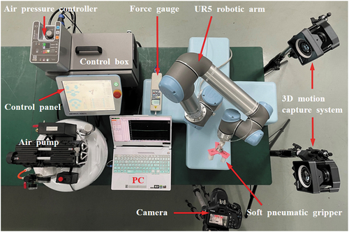
The SPG is fixed at the end of UR5 robotic arm (Universal Robots corporation, located in Denmark) controlled by control box. Through tuning air pressure controller (iPCU2-SMN-1120 V2.83) to regulate the pressure value in air pump (YH-04), and the deformation motion of the SPG can be adjusted. A digital force gauge (HP-20) is used to measure contact force during bending deformation of a single soft actuator, and the movement of the SPG grasping the ball can be measured by a 3D motion capture system (OptiTrack Prime 41). The entire motion process is recorded by a digital camera (Canon, EOS 1300D), and the experimental equipments are shown in .
Figure 10. The experimental equipments.
The detailed grasping control process is as follows:
Step 1: Turn on the power supply and air pump, adjust air pressure to negative pressure, and the gripper is evacuated internally to produce reverse bending deformation;
Step 2: Control the motion of UR5 robotic arm to make the gripper gradually approach the target object;
Step 3: Adjust air pressure to positive pressure, and the gripper gradually changes from reverse bending to positive bending to adaptively contact the target object;
Step 4: Adjust air pressure to positive 35 kPa to make the gripper grasp the target object tightly;
Step 5: Control UR5 robotic arm to move upwards so as to lift the target object.
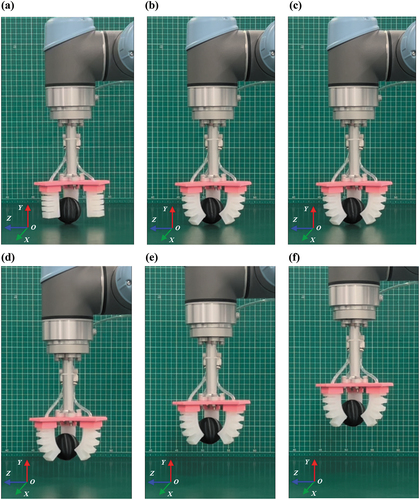
The actual total weight of the fabricated SPG and the ball is measured as 0.98 N, which is close to the theoretical value, and the error between experimental and theoretical values is probably caused by manufacturing. Then, UR5 robotic arm is programmed to rise at a uniform velocity of 24 mm/s, and the grasping states at six different moments are shown in . The six configurations are basically an one-to-one match with that in , which demonstrates a basic comparability between theoretical simulation results and actual experimental ones in terms of deformed configurations of the SPG.
Figure 11. Grasping the ball experiment. (a) t = 0.0 s, (b) t = 0.7 s, (c) t = 3.0 s, (d) t = 4.0 s, (e) t = 5.0 s, (f) t = 6.0 s.
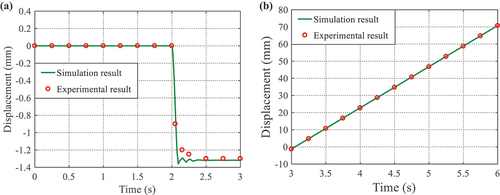
For the sake of easy comparison, we can compare the experiment displacements with simulation results of the ball in Y direction. It can be known from that the simulation results coincide with the experimental ones, which is consistent with the kinematic law of the ball before and after being grasped.
Figure 12. The displacement of the ball in Y direction in two time periods. (a) t = 0.0 s ~ 3.0 s, (b) t = 3.0 s ~ 6.0 s.
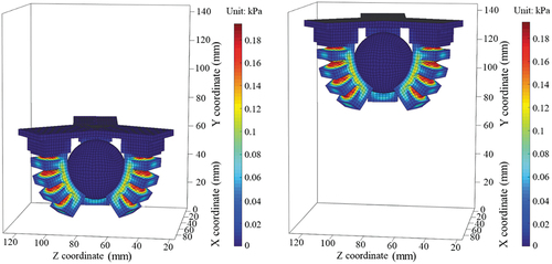
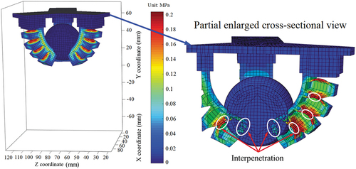
Additionally, we need to consider another situation where there is no frictional contact between the SPG and the ball, and there is also no self-contact for the SPG itself. Similarly, we can conduct simulation and obtain the deformation configuration and von Mises stress variations of the SPG at t = 2.5 s in the case of no frictional contact and self-contact, as shown in the overall view and partial enlarged cross-sectional view in . It can be obviously observed from the white oval area in that an interpenetration phenomenon occurs between adjacent air chambers, and between the SPG and the ball, which indicates that there is no contact interaction between them. They simply undergo their own configuration and displacement variations, which is inconsistent with the practical grasping contact situation.
Figure 13. The deformation configuration and von Mises stress distribution of the SPG at t = 2.5 s.
Furthermore, we can obtain the motion changes of the ball and von Mises stress variations of the SPG by working out EquationEquations (32)(32)
(32) , (Equation37
(37)
(37) ) and (Equation38
(38)
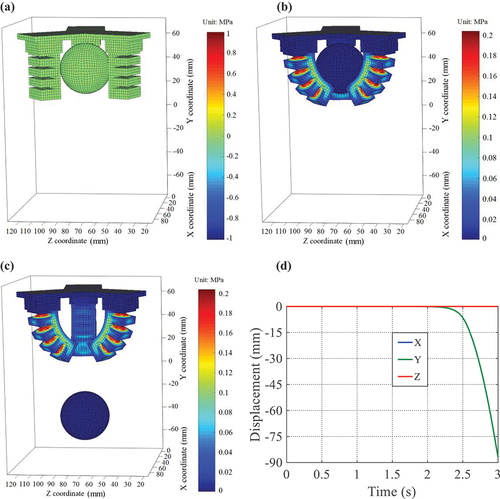
(38) ), as shown in . Initially, the ball is stationary (, starting from t = 2.0 s, the ball is in a free-falling state (, and its displacement versus time curve is half that of the parabola (, which conforms to the law of free-falling motion. However, as is well known, it is almost impossible to conduct grasping operation without frictional contact, as it obviously goes against the motion law of the actual grasping objects.
Figure 14. The motion states of the ball and von Mises stress distribution of the SPG at (a) t = 0.0 s, (b) t = 2.0 s, (c) t = 3.0 s and (d) the displacements of the ball.
In summary, the dynamic modeling method provides a workable solution for accurately analyzing nonlinear deformation and configuration variations of the SPG and simulating contact interaction to avoid interpenetration problem when grasping target objects, which demonstrates the crucial role and influence of contact interaction on grasping manipulation of target objects.
Although the proposed method has lower computational efficiency compared to finite element software, it can stably and accurately predict the output results under external interference when considering contact interaction, including configuration variations, von Mises stress distribution and contact forces, which is instructive and enlightening for actual grasping.
5. Conclusions and further work
In this study, within the framework of ANCF, in consideration of contact interaction between soft gripper and target objects, we present a nonlinear dynamic modeling approach for a three-jaw SPG, whose grasping capability and motion behaviors can be revealed and predicted effectually.
The key contributions of this study are summarized as follows: (i) Creatively combining Coulomb’s friction law with a multiple-point contact method to establish a nonlinear dynamic model for illuminating the SPG’ grasping characteristics, several nonlinear forces and their derivatives are deduced, and the established nonlinear dynamic equations are solved using Generalized-α scheme and Newton-Raphson iterative algorithm; (ii) The proposed nonlinear dynamic approach can not only accurately describe motion displacement, but also reveal the SPG’s grasping configuration, stress distribution and contact forces variations; (iii) Revealing the pivotal role and influence of contact interaction in circumventing interpenetration problem and grasping operation.
In the future, we will be engaged in developing some new computing strategies with the help of data-driven method to improve computational efficiency and balance calculation accuracy. Additionally, efforts will be committed to implanting soft force sensors into SPGs to measure grasping force changes, and exploring the effect of different air pressures on nonlinear deformation behaviors to provide real-time feedback and accurate control, which may inspire potential applications of soft grippers in sophisticated scenes such as deepwater operations and surgical treatments.
Disclosure statement
No potential conflict of interest was reported by the author(s).
Additional information
Funding
References
- Coyle S, Majidi C, LeDuc P, et al. Bio-inspired soft robotics: material selection, actuation, and design. Extreme Mech Lett. 2018;22:51–59. doi:10.1016/j.eml.2018.05.003
- Jackson N, Chastain P, Crowther M, et al. Development of fast prototyping pneumatic actuated grippers. Int J Precis Eng Manuf. 2019;20(12):2183–2192. doi: 10.1007/s12541-019-00231-9
- Zhang B, Xie Y, Zhou J, et al. State-of-the-art robotic grippers, grasping and control strategies, as well as their applications in agricultural robots: a review. Computers And Electronics In Agriculture. 2020;177:105694. doi:10.1016/j.compag.2020.105694
- Ren L, Li B, Wei G, et al. Biology and bioinspiration of soft robotics: actuation, sensing, and system integration. iScience. 2021;24(9):103075. doi:10.1016/j.isci.2021.103075
- Terrile S, Argüelles M, Barrientos A. Comparison of different technologies for soft robotics grippers. Sensors. 2021;21(9):3253. doi:10.3390/s21093253
- Shintake J, Cacucciolo V, Floreano D, et al. Soft robotic grippers. Adv Mater. 2018;30(29):1707035. doi:10.1002/adma.201707035
- Ilievski F, Mazzeo AD, Shepherd RF, et al. Soft robotics for chemists. Angewandte Chemie. 2011;50(8):1890–1895. doi:10.1002/anie.201006464
- Martinez RV, Branch JL, Fish CR, et al. Robotic tentacles with three-dimensional mobility based on flexible elastomers. Adv Mater. 2013;25(2):205–212. doi: 10.1002/adma.201203002
- Deimel R, Brock O. A novel type of compliant and underactuated robotic hand for dexterous grasping. Int J Rob Res. 2016;35(1–3):161–185. doi:10.1177/0278364915592961
- Hu W, Alici G. Bioinspired three-dimensional-printed helical soft pneumatic actuators and their characterization. Soft Rob. 2020;7(3):267–282. doi:10.1089/soro.2019.0015
- Hao Y, Gong Z, Xie Z, et al. A soft bionic gripper with variable effective length. J Bionic Eng. 2018;15(2):220–235. doi:10.1007/s42235-018-0017-9
- Hao Y, Liu Z, Liu J, et al. A soft gripper with programmable effective length, tactile and curvature sensory feedback. Smart Mater Struct. 2020;29(3):035006. doi: 10.1088/1361-665X/ab6759
- Zhang H, Liu W, Yu M, et al. Design, fabrication, and performance test of a new type of soft-robotic gripper for grasping. Sensors. 2022;22(14):5221. doi:10.3390/s22145221
- Terryn S, Brancart J, Lefeber D, et al. Self-healing soft pneumatic robots. Sci Rob. 2017;2(9):eaan4268. doi:10.1126/scirobotics.aan4268
- Justus KB, Hellebrekers T, Lewis DD, et al. A biosensing soft robot: autonomous parsing of chemical signals through integrated organic and inorganic interfaces. Sci Rob. 2019;4(31):eaax0765. doi:10.1126/scirobotics.aax0765
- Liu X, Zhao Y, Geng D, et al. Soft humanoid hands with large grasping force enabled by flexible hybrid pneumatic actuators. Soft Rob. 2021;8(2):175–185. doi:10.1089/soro.2020.0001
- Wu M, Zheng X, Liu R, et al. Glowing sucker octopus (stauroteuthis syrtensis)-inspired soft robotic gripper for underwater self-adaptive grasping and sensing. Adv Sci. 2022;9(17):e2104382. doi:10.1002/advs.202104382
- Zhang Z, Long Y, Chen G, et al. Soft and lightweight fabric enables powerful and high-range pneumatic actuation. Sci Adv. 2023;9(15):eadg1203. doi:10.1126/sciadv.adg1203
- Zhou X, Majidi C, O’Reilly OM. Soft hands: an analysis of some grasping mechanisms in soft robot design. Int J Solids Struct. 2015;64–65:155–165. doi: 10.1016/j.ijsolstr.2015.03.021
- De Payrebrune KM, O’Reilly OM. On the development of rod-based models for pneumatically actuated soft robot arms: a five-parameter constitutive relation. Int J Solids Struct. 2017;120:226–235. doi:10.1016/j.ijsolstr.2017.05.003
- Uppalapati NK, Krishnan G. Towards pneumatic spiral grippers: modeling and design considerations. Soft Rob. 2018;5(6):695–709. doi:10.1089/soro.2017.0144
- Hao Y, Wang T, Ren Z, et al. Modeling and experiments of a soft robotic gripper in amphibious environments. Int J Adv Rob Syst. 2017;14(3):1–12. doi: 10.1177/1729881417707148
- Gong Z, Cheng J, Chen X, et al. A bio-inspired soft robotic arm: kinematic modeling and hydrodynamic experiments. J Bionic Eng. 2018;15(2):204–219. doi:10.1007/s42235-018-0016-x
- Wu Z, Li X, Guo Z. A novel pneumatic soft gripper with a jointed endoskeleton structure. Chin J Mech Eng. 2019;32(1):1–12. doi:10.1186/s10033-019-0392-0
- Gu G, Wang D, Ge L, et al. Analytical modeling and design of generalized pneu-net soft actuators with three-dimensional deformations. Soft Rob. 2021;8(4):462–477. doi:10.1089/soro.2020.0039
- Lotfiani A, Yi X, Shao Z, et al. Analytical modeling and optimization of a corrugated soft pneumatic finger considering the performance of pinch and power grasps. Extreme Mech Lett. 2021;44:101215. doi:10.1016/j.eml.2021.101215
- Alici G, Canty T, Mutlu R, et al. Modeling and experimental evaluation of bending behavior of soft pneumatic actuators made of discrete actuation chambers. Soft Rob. 2018;5(1):24–35. doi:10.1089/soro.2016.0052
- Zhong G, Hou Y, Dou W. A soft pneumatic dexterous gripper with convertible grasping modes. Int J Mech Sci. 2019;153–154:445–446. doi: 10.1016/j.ijmecsci.2019.02.028
- Zhang Z, Wang X, Meng D, et al. Bioinspired spiral soft pneumatic actuator and its characterization. J Bionic Eng. 2021;18(5):1101–1116. doi: 10.1007/s42235-021-00075-y
- Mustaza SM, Elsayed Y, Lekakou C, et al. Dynamic modeling of fiber-reinforced soft manipulator: a visco-hyperelastic material-based continuum mechanics approach. Soft Rob. 2019;6(3):305–317. doi:10.1089/soro.2018.0032
- Caasenbrood BJ, Pogromskiy AY, Nijmeijer H. Dynamic modeling of hyper-elastic soft robots using spatial curves. IFAC-Papersonline. 2020;53(2):9238–9243. doi: 10.1016/j.ifacol.2020.12.2209
- Xu Q, Liu J. Effective enhanced model for a large deformable soft pneumatic actuator. Acta Mech Sin. 2020;36(1):245–255. doi: 10.1007/s10409-019-00903-9
- Rothemund P, Kim Y, Heisser RH, et al. Shaping the future of robotics through materials innovation. Nature Mater. 2021;20(12):1582–1587. doi:10.1038/s41563-021-01158-1
- Holland D, Park EJ, Polygerinos P, et al. The soft robotics toolkit: shared resources for research and design. Soft Rob. 2014;1(3):224–230. doi:10.1089/soro.2014.0010
- Olshevskiy A, Dmitrochenko O, Kim C-W. Three-dimensional solid brick element using slopes in the absolute nodal coordinate formulation. J Comput Nonlin Dyn. 2014;9(2):02100. doi: 10.1115/1.4024910
- Shabana AA. Continuum-based geometry/analysis approach for flexible and soft robotic systems. Soft Rob. 2018;5(5):613–621. doi:10.1089/soro.2018.0007
- Otsuka K, Makihara K, Sugiyama H. Recent advances in the absolute nodal coordinate formulation: literature review from 2012 to 2020. J Comput Nonlin Dyn. 2022;18(7):080803. doi: 10.1115/1.4054113
- Orzechowski G, Fraczek J. Nearly incompressible nonlinear material models in the large deformation analysis of beams using ANCF. Nonlinear Dyn. 2014;82(1–2):451–464. doi: 10.1007/s11071-015-2167-1
- Jung SP, Park TW, Chung WS. Dynamic analysis of rubber-like material using absolute nodal coordinate formulation based on the non-linear constitutive law. Nonlinear Dyn. 2010;63(1–2):149–157. doi: 10.1007/s11071-010-9792-5
- Konyukhov A, Izi R. Introduction to computational contact mechanics: a geometrical approach. (NY): John Wiley & Sons, Ltd; 2015.
- Konyukhov A, Schweizerhof K. Computational contact mechanics: geometrically exact theory for arbitrary shaped bodies. (NY): Springer; 2012.
- Karnopp D. Computer simulation of stick-slip friction in mechanical dynamic systems. J Dyn Syst Meas Control. 1985;107(1):100–103. doi:10.1115/1.3140698
- Arnold M, Brüls O. Convergence of the generalized-α scheme for constrained mechanical systems. Multibody Sys Dyn. 2007;18(2):185–202. doi:10.1007/s11044-007-9084-0
- Dagnachew BS, Meuwissen TH. E.: A fast Newton–Raphson based iterative algorithm for large scale optimal contribution selection. Genet Sel Evol. 2016;48(1):70. doi: 10.1186/s12711-016-0249-2
- Xu Q, Liu J. An improved dynamic model for silicone material beam with large deformation. Acta Mech Sin. 2018;34(4):744–753. doi: 10.1007/s10409-018-0759-y
- Yuan T, Tang L, Liu Z, et al. Nonlinear dynamic formulation for flexible origami-based deployable structures considering self-contact and friction. Nonlinear Dyn. 2021;106(3):1789–1822. doi:10.1007/s11071-021-06860-y
- Pennestrì E, Rossi V, Salvini P, et al. Review and comparison of dry friction force models. Nonlinear Dyn. 2016;83(4):1785–1801. doi:10.1007/s11071-015-2485-3