
Abstract
Mahabaleshwar is one of the most attractive and important destinations for tourists in Maharashtra, India, which experiences frequent slope failure due to high-intensity rain and complex geological conditions. The litho unit of the area is the Deccan Trap Basalt, the most famous consecutive basaltic flows during the late Cretaceous to Tertiary periods. The area is very susceptible to weathering, different degrees of alteration, formation of soils and occurrences of bole beds in between two consecutive basaltic flows. Soil formation process in this area is one of the most influencing factors for slope failure; in addition to this, joints, sub-vertical-to-vertical slopes, heavy rainfalls, etc. also play a pivotal role in instability. These transformed soils create instability on the slopes and ultimately converge to slope failures. Five types of soils have been identified during field investigations, petrographic study and X-ray diffraction that indicate change in composition and colour variations. Geomechanical properties viz. bulk density, grain size analysis, Atterberg limit, uniaxial compressive strength, cohesion and angle of internal friction were calculated for five types of soil samples. Effects of these soils on slope stability have been depicted with the help of numerical program Slide 6.0 based on limit equilibrium method.
1. Introduction
Highways and roadways in hilly terrains are very important means for public transportation and connection from one location to another. Construction of highways in hilly regions is a very challenging task for engineers. The impact of geomaterials and geological heterogeneities encompasses on the stability of slopes. Generally, a slope failure initiates from one or combinations of factors like structural discontinuities (conditions and orientations), weathering and alteration of geomaterials, developments of weak zone, lithological disturbances, slope conditions, heavy rainfalls and many more (Singh & Singh Citation1992). Weathering and alteration of geomaterials favour the lithological disturbances and also help in the formation of soil that adversely affect on the stability of slopes. Moreover, unplanned highway constructions in such areas always pose a serious threat to human life, property and lands, whereas a well-planned field survey and appropriate design of slopes can prevent the loss of life, property and anonymous future accidents (Singh et al. Citation2008, Citation2013a; Pradhan et al. Citation2011).
Numerous conventional and numerical tools are being used to calculate factor of safety (FoS) viz. limit equilibrium method (LEM), finite element method (FEM), finite difference method (FDM) and distinct element method (DEM). The conventional techniques mainly include kinematic analysis and limit equilibrium techniques (Duncan & Wright, Citation1980; Kim et al. Citation2002; Kumar & Sanoujam Citation2007; Umrao et al. Citation2011). LEM is the conventional tool which is routinely used in analysis of loose slope soil/debris etc., whereas translational or rotational movements occur on distinct failure (Vishal et al. Citation2010; Singh et al. Citation2013b). The conventional analyses are undertaken to provide either an FoS or, through back-analysis, a range of shear strength parameters at failure. During the past three decades, various methods have been proposed for performing the two-dimensional (2-D) LEM of slices. These methods are (1) Fellenius’ method (Fellenius Citation1936), (2) simplified Bishop method (Bishop Citation1955), (3) Janbu's simplified method (Janbu et al. Citation1956) and (4) Spencer's method (Spencer Citation1967).
Fellenius’ method is one of the simplest methods among all to analyse the short-term stability for both homogeneous and inhomogeneous slopes and it is based on the assumptions that a rigid, cylindrical block will fail by rotation about its centre and that the friction angle is 0. So, the shear strength is assumed to be due to cohesion only. Bishop Citation(1955) proposed the simplified Bishop method that also uses the same method of slices to find the FoS for soil mass. The Janbu's simplified method (1956) is a slicing method for non-circular slip surfaces. The method assumed that the inter-slice forces are horizontal and thus the shear forces are 0. In the late 1960s, Spencer Citation(1967) purposed two factors of safety equations, one with respect to moment equilibrium and another with respect to horizontal force equilibrium. He adopted a constant relationship between the inter-slice shear and normal forces and, through an iterative procedure, altered the inter-slice shear-to-normal ratio until the two factors of safety became the same.
The present study deals with the geomechanical characterization of soils exposed on the slopes of state highway (SH)-72 of Maharashtra, India. Relevant data have been determined from field survey and laboratory testing, which were used for the simulation of the stability of slopes by LEM using software package Slide 6.0 (Rocscience Inc. Citation2010a) with the simplified Bishop slicing method.
2. Study area
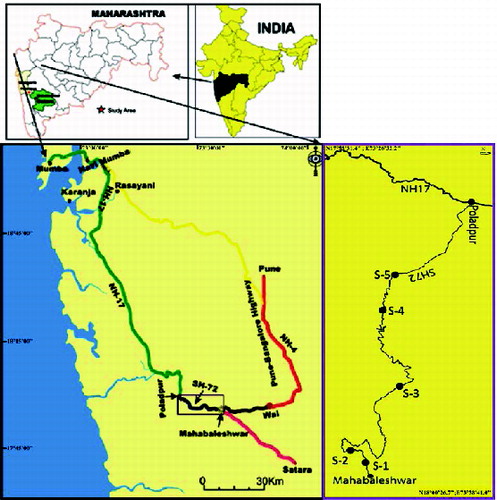
SH-72 of Maharashtra is a state highway between Poladpur and Mahabaleshwar that is chosen for the study area. Mahabaleshwar, located in Satara district of Maharashtra, is a famous hill station and lies at a distance of about 120 km and 285 km from Pune and Mumbai, respectively. Mahabaleshwar is a perfect place for vacations and it offers numerous opportunities for leisure activities like fishing, boating and trekking. Beautiful lakes, hills and waterfalls are the most attractive features of the hill station and that makes the place famous. Moreover, it also attracts people due to its unique scenic beauty as well as temples, natural view points and places of historical significance. The study area falls between latitude 17° 52′ 30″-18° 00′ 00″ and longitude 73° 26′ 15″-73° 41′ 15″. It comes within the toposheet no. 47G/9 NE, allocated by the Survey of India (SOI). The national highway, NH-17, provides an arterial link to Mahabaleshwar connecting it to the state highway, SH-72, after it stretches from Mumbai to Poladpur and finally the same highway (SH-72) connects to Mahabaleshwar () (Ahmad Citation2012; Ahmad et al. Citation2013).
Figure 1. Location of the study area (purple-coloured rectangle shows study area).
3. Geology of the area
The study area belongs to a well-known, large extent of volcanic eruptions between the late Cretaceous to Tertiary periods known as the Deccan Trap Basalt. It is widely erupted about in a 50,000 km2 of Western Indian states like Andhra Pradesh, Maharashtra and parts of Central India (Mahoney et al. Citation1982). In Maharashtra, the Deccan Trap Basalt is divided into three subgroups viz. Kalsubai, Lonavala and Wai. The study area comprises three lower formations of the Wai subgroup viz. Poladpur Formation, Ambenali Formation and Mahabaleshwar Formation. These formations are differentiated by minor mineralogical changes, isotope ratios and magnetic polarity (). The study area represents two types of basalt, namely glomeroporphyritic and simple olivine basalt, based on textures (Beane et al. Citation1986). Poladpur formation basalt is glomeroporphyritic with vesicles, commonly oxidized tops. They are fine-to-medium grained, typically carrying medium-grained phenocrysts of plagioclase, plagioclase+augite or plagioclase+augite+olivine. The Ambenali Formation comprises the same type of rock but low isotopic ratio (Beane et al. Citation1986) resting on the Poladpur Formation and capped by the Mahabaleshwar Formation, whereas the Mahabaleshwar Formation is comparatively less exposed and capped above the Ambenali Formation. The rocks of Mahabaleshwar Formation are medium-to-fine grained, typical uniform distribution of olivine and augite in the laths of plagioclase. All three formations carry uniform and almost equal distribution of iron oxides.
Table 1. Simplified stratigraphy of Deccan Trap Basalt with formation thickness, Sr isotope ratio and magnetic polarity (after Peng et al. Citation1994; Radhakrishna & Vaidyanadhan Citation1994).
The study area also encompasses different types of soils, commonly on the top of the hills. During the field survey, five types of soil have been identified on the basis of colouration and physical natures. X-ray diffraction analysis () differentiates by minerals present in these soils. The data represents the changes in mineralogy of soils, that is, presence of different iron constituents. The short descriptions of each soil type have been given in . The soil colours are mentioned using the Munsell soil colour chart (Munsell Citation1992). To classify the soils, samples were sieved and obtained data were plotted at semi-log graphs.
Table 2. Brief description of the soils.
4. Field investigations and methodology
Extensive field investigations were performed to collect representative soil and rock samples as per the code. Testings were performed in the laboratory for different geoengineering properties as per American Society for Test and Materials (ASTM) and International Society for Rock Mechanics (ISRM) standards. Also, the detail methodology has been explained below.
4.1. Methodology for determination of geoengineering properties
4.1.1. Preparation of specimens
Specimens were prepared in accordance with different ASTM codes as per the test requirement. Prior to preparing the test specimens, the materials were air dried and broken into smaller possible fragments, care being taken not to reduce the sizes of the individual particles.
4.1.2. Test procedures
The following tests viz. bulk density, sieve analysis, Atterberg limits, unconfined compressive strength (UCS) and shear strength parameters were determined for each soil type on disturbed samples. The procedures are as follows.
4.1.3. Bulk density
Density is a very useful concept in geotechnical engineering and also for slope stability analysis. In this analysis, bulk density has been considered and it is defined as the oven-dry weight of a unit volume of soil inclusive of pore spaces. The bulk density of a soil is always smaller than its particle density. It normally decreases as the soil texture become finer. The bulk density was performed as per ASTM D7263 Citation(1994).
4.1.4. Sieve analysis
The test sample for mechanical analysis was prepared as per outlined in practice ASTM D421 Citation(2007) and analyses were performed as per ASTM D422 Citation(2007). A representative sample of approximately 500 g was used for each test after washing and being oven dried. The sieving was done by a mechanical method using automatic shakers and a set of ASTM sieves.
4.1.5. Liquid limit determination
Soil sample passing through a 425-μm sieve, weighing 200 g was mixed with water to form a thin homogeneous paste. The paste was collected inside the Casagrande's apparatus cup with a grove created, and the number of blows to close it was recorded. Also, moisture contents were determined for the respective sample tested for liquid limit (ASTM D4318 Citation1994).
4.1.6. Plastic limit
About 15 g of soil, passing through a No. 40 sieve, is mixed thoroughly. The soil is rolled on a glass plate with the hand until it is about 3 mm in diameter. This procedure of mixing and rolling is repeated till the soil shows signs of crumbling. The water content of the crumbled portion of the thread is determined.
4.1.7. Plasticity index
Plasticity index (PI) indicates the degree of plasticity of a given soil. Greater the difference between liquid and plastic limits, greater is the plasticity of the soil. Cohesion-less soil has PI = 0. Such soils are termed non-plastic. Atterberg classifies the soils according to their plasticity indices as in .
Table 3. Soil classifications according to PI (ASTM D4318 Citation1994).
4.1.8. Unconfined compressive strength
Consistency of undisturbed soil varies quantitatively on the basis of its UCS. The UCS, qu, is defined as the ultimate load per unit cross-sectional area that a cylindrical specimen of soil (with aspect ratio of 2.0–2.5) can take under compression without any lateral pressure (ASTM D2166 1994). Moisture content in the sample is assumed to remain constant during the duration of the test that generally takes only a few minutes. indicates the relationship between consistency and qu. A schematic diagram of UCS test is illustrated in .
Table 4. Relationship between consistency of soil and qu.
Figure 2. Bulk density of soil samples.
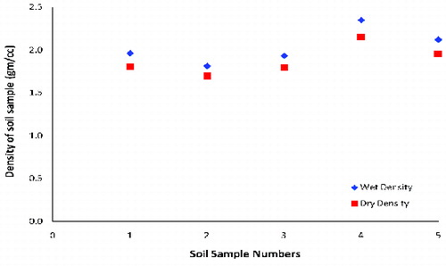
Figure 3. Grain size of different samples based on sieve analysis.
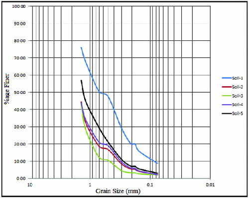
Figure 4. Atterberg limits for different types of soil samples (LL = liquid limit, PL = plastic limit and PI = plasticity index).
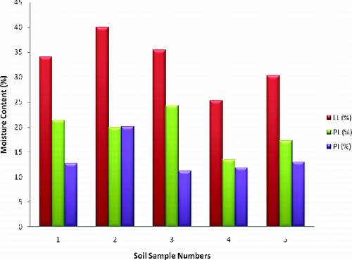
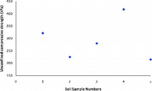
Figure 5. UCS values for different soil types.
4.1.9. Shear strength parameters
The shear strength parameters, cohesion (c) and angle of internal friction (φ), of soils were determined under triaxial compression test (TCT). The test was performed as per ASTM D2850 (2007). In the TCT, three or more identical samples of soil are subjected to uniformly distributed fluid pressure around the cylindrical surface.
4.2. Methodology for slope stability evaluation
2-D limit equilibrium slope stability analyses (Duncan Citation1996) have been carried out using the commercially available software package Slide 6.0 (Rocscience Inc. Citation2010a), which is widely used in geotechnical engineering for slope stability assessments. The simplified Bishop method was adopted for simulation because it suited for soil masses and was close to realistic results. However, several assumptions were made in this method.
The failure is assumed to occur by rotation of a mass of soil on a circular slip surface centred on a common point. Thus, Bishop's method should not be used to compute the FoS for non-circular surfaces unless a frictional centre of rotation is used (Anderson & Richards Citation1987).
The forces on the sides of the slice are assumed to be horizontal and thus there are no shear stresses between the slices (Bishop Citation1955).
The total normal force is assumed to act at the centre of the base of each slice and is derived by summing the forces in a vertical direction.
5. Results and discussion
5.1. Bulk density
Bulk densities of soils have been calculated in dry and saturated conditions. The result () indicates density range between 1.69 and 1.95 g/cc in dry condition and 1.81 and 2.12 g/cc in wet condition for the soil samples S-1, S-2, S-3 and S-5. The average density of sample S-4 has been calculated as 2.15 g/cc and 2.35 g/cc in dry and wet conditions, respectively.
5.2. Particle size distribution
From the plot between percentage finer versus grain sizes (), uniformity coefficient (Cu) and coefficient of curvature (Cc) were determined for each soil type (). On the basis of results, Cc of each soil lies between 1 and 3, which implies that all five soils are well graded. Cu of soil samples S-2 and S-5 are classified as well-graded gravel, whereas S-1 and S-4 are classified as well-graded sand. Sample S-3 calculated as the Cu value less than 4.0 that indicates uniform distribution of soils.
Table 5. Cu, Cc and classification of soils.
5.3. Atterberg limits
The liquid limit value of the five soils ranges between 25.37% and 40.04%, while the plastic limits were calculated as 13.47%–24.31% (). The range of PI values of different soils is calculated as 11.90–17.87. According to Atterberg classification of soil, sample nos. S-1, S-3, S-4 and S-5 are medium plastic, whereas sample no. S-2 is highly plastic.
5.4. Unconfined compressive strength
The UCS values of different soils have been shown in . Soil sample no. S-2 represents the lowest value, whereas sample no. S-4 indicates the highest value. According to relationship between consistency and UCS, the soil sample nos. S-1, S-3 and S-5 are very stiff soils and sample no. S-2 is stiff soil, whereas sample no. S-4 is hard soil.
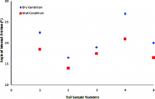
5.5. Shear strength parameters
The shear strength parameters c and φ are shown in and , respectively. For the estimation of these two parameters, TCT laboratory tests have been performed in dry and wet conditions. These parameters including density are required for the simulation of slope stability.
Figure 6. Cohesion of soil samples in dry and saturated conditions.
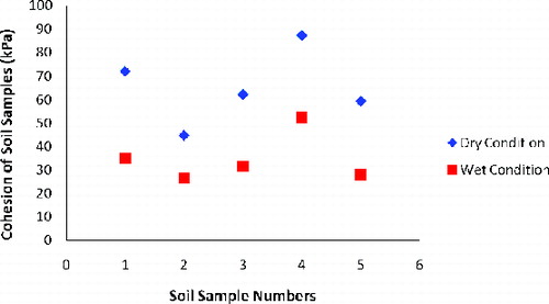
Figure 7. Angle of internal frictions in dry and wet conditions for different soil types.
5.6. Slope stability analysis
The road cut hills of SH-72 from Poladpur to Mahabaleshwar are alarming roads due to frequent landslides, rockfalls and soil failures. In particular, high hill regions are much prone to slope failure and their results are devastating. These high hill regions are near to Mahabaleshwar town and most of the road cut slopes have steep angle slopes. A rockfall study in high hill rock slopes of the same area have been done (Ahmad et al. Citation2013) and found the major cause of rockfall in this area was due to heavy rainfall during rainy season and nearly parallel joints to the slope face. The area was also troubled due to formation of basaltic soils, which creates failure of slopes. During the field study, many places have been identified where slope failure occurred due to formation of different types of soils from basaltic rocks. The high angle of cut slopes along the roads is measured as 65°–75°. The average angle of cut slopes has been measured as about 70° for soil slope. The site is prone to failure.
To evaluate the stability of soil slopes exposed above basaltic base, 2-D LEM was adopted. The simplified Bishop method was chosen from various LEMs, due to its specialty for soil masses. The geoengineering properties of different soils and basaltic rocks were used in the simulation. The properties of intact rock samples have been evaluated in laboratory as per ISRM (). Obtained properties are changed for weathered and fractured basaltic rock using the RocLab program (Rocscience Inc. Citation2010b).
Table 6. Geoengineering properties of intact basaltic rock for dry and saturated condition.
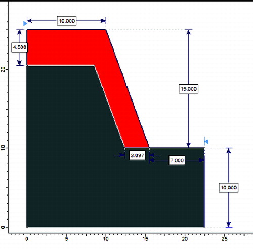
On the basis of field survey, the maximum height of slope has been taken 15 m above the road and the average slope angle 70° was taken for all slopes, 4.5 m soil bed on the top of the slope and about 3 m soil layer have been taken above the slope (). The aim of the study is to see the impact of five different types of soils on the basaltic base slope. To analyse the impact, the geoengineering properties of soil sample no. S-1 are applied on slope no. SL-1. Similarly, for slope no. SL-2, the geoengineering properties of soil sample no. S-2 are applied and so on.
Figure 8. Geometry of slope.
and represent the contours of FoS in the slip centre grid and slope showing all slip surfaces generated by the analysis. The contours are based on the minimum calculated FoS at each grid slip centre. The global minimum slip surface, for the Bishop simplified analysis method, which is the slip surface with the lowest FoS, of all slip surfaces analysed is also shown in and .
Figure 9. FoS of soil slopes in dry condition.
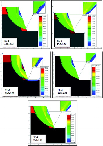
Figure 10. FoS of soil slopes in wet condition.
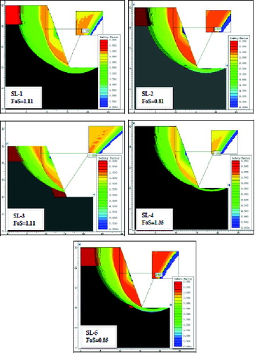
The FoS of the five soils ranges between 1.76 and 2.34 in dry conditions (), whereas 0.81–1.35 in wet conditions indicates the impact of rains on reduction of FoS (). The results of simulations indicate that, in dry conditions, all five slopes are safe and there are no chances of slope failure. In the saturated condition, results are very different from the dry condition. Slope nos. SL-2 and SL-5 are unstable and slope nos. SL-1 and SL-3 are critically unstable, whereas slope no. SL-4 is in stable condition.
6. Conclusions
The paper is an attempt to study the physical and engineering behaviour of five types of basaltic soils and their usefulness on the stability of slopes of SH-72. The following important conclusions have been drawn.
Field observations, petrographic examinations and X-ray diffraction (XRD) analysis of the soils were pioneer steps in the distinction of each soil.
From the different geoengineering properties, five types of soils have been classified. Soil sample S-1 is classified as well-graded sand, medium plastic and very stiff soil. Soil sample S-2 is well-graded gravel, highly plastic and stiff soil. Soil sample S-3 is uniformly distributed, medium plastic and very stiff soil. Soil sample S-4 is well-graded gravel, low plastic and hard soil. Soil sample S-5 is well-graded sand, medium plastic and very stiff soil.
From the geoengineering properties, it is found that S-2 shows low strength, whereas S-4 exhibits high strength among the five soil types. The behaviours of the remaining soils are almost similar and have almost the same strength.
Petrographically, S-2 is laterite soil which is comparatively weak soil, whereas S-4 is reddish-yellow loam soil which is comparatively hard soil. Thus, laterite soil is fragile in nature and most deleterious in the scenario of vulnerability.
From the slope stability evaluation using LEM, laterite soil has the lowest FoS as 0.81 and reddish-yellow loam has the highest FoS as 1.35 in wet conditions. This indicates that laterite soil is unstable and reddish loam soil is stable. The other three soils are critically stable.
Acknowledgements
Author expresses sincere thanks to the editor and reviewers for valuable suggestions that helped a lot to improve the manuscript.
References
- Ahmad M. 2012. Landslide assessments along the road-cut slopes of SH-72, Maharashtra, India [ dissertation]. Bombay: Indian Institute of Technology.
- Ahmad M, Umrao RK, Ansari MK, Singh R, Singh TN. 2013. Assessments of rockfall along the road-cut slopes of SH-72, India. Geomaterials. 3(1):15–23.
- Anderson MG, Richards KS. 1987. Slope stability: geotechnical engineering and geomorphology. Chichester: John Wiley and Sons; p. 648, ISBN 047191021X.
- ASTM Standard D7263 – 09. 1994. Standard test methods for laboratory determination of density (unit weight) of soil specimens. Annual book of ASTM standards, 04.08. Philadelphia (PA): ASTM.
- ASTM Standard D4318-10. 1994. Standard test methods for liquid limit, plastic limit, and plasticity index of soils. Annual book of ASTM standards, 04.08. Philadelphia (PA): ASTM.
- ASTM Standard D2166 – 06. 1994. Standard test method for unconfined compressive strength of cohesive soil. Annual book of ASTM standards, 04.08. Philadelphia (PA): ASTM.
- ASTM Standard D422-63. 2007. Standard test method for particle-size analysis of soils. Annual book of ASTM standards, 04.08. Philadelphia (PA): ASTM.
- ASTM Standard D421-85. 2007. Standard practice for dry preparation of soil samples for particle-size analysis and determination of soil constants. Annual book of ASTM standards, 04.08. Philadelphia (PA): ASTM.
- ASTM Standard D2850-03a. 2007. Standard test method for unconsolidated-undrained triaxial compression test on cohesive soils. Annual book of ASTM standards, 04.08. Philadelphia (PA): ASTM.
- Beane JE, Turner CA, Hooper PR, Subbarao KV, Walsh JN. 1986. Stratigraphy, composition and form of the Deccan Basalts, Western Ghats, India. B Volcanol. 48:61–83.
- Bishop AW. 1955. The use of the slip circle in the stability analysis of earth slopes. Geotechnique. 5(1):7–17.
- Duncan JM. 1996. State of the art: limit equilibrium and finite-element analysis of slopes. J Geotech Eng. 122(7):577–596.
- Duncan SG, Wright SG. 1980. The accuracy of equilibrium methods of slope stability analysis. Eng Geol. 16(1):5–17.
- Fellenius W. 1936. Calculation of the stability of earth dams. Proceedings of the Second Congress of Large Dams, Washington, 4: pp. 445–463.
- Janbu N, Bjerrum L, Kjaernsli B. 1956. Soil mechanics applied to some engineering problems. Oslo: Norwegian Geotechnical Institute. Publication 16.
- Kim J, Salgado R, Lee J. 2002. Stability analysis of complex soil slopes using limit analysis. J Geotech Geoenviron. 128(7):546–557.
- Kumar A, Sanoujam M. 2007. Landslide studies along the national highway (NH 39) in Manipur. Nat Hazards. 40(3):603–614.
- Mahoney J, Macdougall JD, Lugmair GW, Murali AV, Das MS, Gopalan K. 1882. Origin of the Deccan Trap flows at Mahabaleshwar inferred from Nd and Sr isotopic and chemical evidence. Earth Planet Sc Lett. 60(1):47–60.
- Munsell Color. 1992. Munsell soil color charts. Revised ed. Newburgh (NY): Maebeth, Division of Kollmoigue Instruments Corp.
- Peng ZX, Mahoney JJ, Hooper PR, Harris C, Beane J. 1994. A role for lower continental crust in flood basalt genesis? Isotopic and incompatible element study of the lower six formations of the western Deccan Traps. Geochim Cosmochim Ac. 58:267–288.
- Pradhan SP, Vishal V, Singh TN. 2011. Slope mass rating for evaluation of health of slopes in an opencast mine in Jharia coalfield, India. Min Eng J. 12(10):36–40.
- Radhakrishna BP, Vaidyanadhan R. 1994. Geology of Karnataka. Bangalore: Geological Society of India.
- Rocscience Inc. 2010a. Slide v6.0 – two-dimensional limit-equilibrium analysis of soil and rock slopes. Toronto: Rocscience Geomechanics Software and Research. Available from: http://www.rocscience.com/products/8/Slide.
- Rocscience Inc. 2010b. Roclab v 1.0 – rock mass strength analysis using the generalized Hoek–Brown failure criterion. Toronto: Rocscience Geomechanics Software and Research. Available from: http://www.rocscience.com/products/14/RocLab.
- Singh TN, Ahmad M, Kainthola A, Singh R, Kumar S. 2013a. A stability assessment of a hill slope – an analytical and numerical approach. Int J Earth Sci Eng. 6(1):39–49.
- Singh TN, Gulati A, Dontha L, Bhardwaj V. 2008. Evaluating cut slope failure by numerical analysis—a case study. Nat Hazards. 47(2):263–279.
- Singh TN, Pradhan SP, Vishal V, 2013b. Stability of slopes in a fire prone mine in Jharia coalfield, India. Arab J Geo. 6:419–421.
- Singh TN, Singh DP. 1992. Prediction of instability of slopes in an opencast mine over old surface and underground workings. Int J Min Reclamat Environ. 6(2):81–89.
- Spencer E. 1967. A method of analysis of embankments assuming parallel interslice forces. Geotechnique. 17:11–26.
- Umrao RK, Singh R, Ahmad M, Singh TN. 2011. Stability analysis of cut slopes using continuous slope mass rating and kinematic analysis in Rudraprayag District, Uttarakhand. Geomaterials. 1:79–87.
- Vishal V, Pradhan SP, Singh TN. 2010. Instability assessment of mine slope–a finite element approach. Int J Earth Sci Eng. 3(6):11–23.