
Abstract
The present study evaluates the dynamic behaviour of the Ermenek Dam, the second highest dam in Turkey, based on conventional geodetic measurements and Finite Element Model (FEM) analyses during its first filling period. In total, eight periods of measured deformation are considered from the end of construction until the reservoir reached its full capacity. The displacement response of the dam to the reservoir level and to seasonal temperature variations is examined in detail. Time series of apparent total displacements at the middle of the crest of the dam exhibits periodicity and linear trends. Correlation analysis revealed that periodic and linear displacement responses of the dam are related to variations of seasonal temperature and linearly increased reservoir level, respectively, indicating a relation between temperature, water load and dam deformation. It is also concluded that measured deformations based on geodetic data show good agreement with the predicted deformation obtained by the FEM analysis.
1. Introduction
The importance of water and structures associated with water is increased day by day due to the growing population. Dams are among the most important man-made structures storing a large amount of water for electricity generation, flood control, agricultural uses, drinking, etc. Large dams have strong interactions with environmental, hydraulic and geomechanical factors more than other engineering constructions, such as air and water temperature, water level, pore pressure and uplift, rock deformability and so on, each of which influences the structural behaviour (Sortis & Paoliani Citation2007). Therefore, monitoring the response of large dams is very crucial and necessary to evaluate their structural condition and reliability.
Until recently, many studies were conducted concerning monitoring structural responses of dams, specifically, earth dams (Guler et al. Citation2006; Bayrak Citation2008; Gikas & Sakellariou Citation2008a; Ehiorobo & Ehigiator Citation2011; Kalkan Citation2014) and concrete dams (Pytharouli & Stiros Citation2005; Sortis & Paoliani Citation2007) on the bases of geodetic and geotechnical methods. Guler et al. (Citation2006) evaluated the surface movements of Alibey Earth Dam (Istanbul) by means of geodetic and geotechnical methods. Geodetic displacement measurements were analyzed using the Karlsruhe method. The geodetic measurement results were compared with Finite Element Model (FEM) analyses and generally a good agreement was observed. Bayrak (Citation2008) dealt with the modelling of the relationships between displacement and reservoir water levels of the Yamula Dam. The author developed a new dynamic deformation analysis technique to investigate whether the rising reservoir level is responsible for the vertical and horizontal movements during the first filling period. The results showed that the reservoir water level changes are an important triggering factor for the Yamula Dam deformations. Gikas and Sakellariou (Citation2008a) investigated the long-term settlement behaviour of the Mornos Earth Dam in Greece. Precise levelling data were used for monitoring measured deformations and the results obtained were compared with those from a numerical back analysis model. Comparative evaluation of the results showed a very good agreement of the order of 0.03 m between the measured and computed deformations. Aguilera et al. (Citation2008) proposed an approach for structural monitoring of large dams using a three-dimensional (3D) Terrestrial Laser Scanner (TLS). They considered aspects related to the accuracy control in georeferencing, together with rigorous approaches to model complex structures. Radial Basis Function and re-Weighted Extended Orthogonal Procrustes analysis were used for surface parameterization and georeferencing, respectively. The results showed that a TLS sensor alone is not enough for providing the structural control of large dams, since it is impossible to monitor the same point in different measurement periods. Ehiorobo and Ehigiator (Citation2011) utilized the differential global positioning system (GPS) technique for monitoring horizontal movements in the Ikpoba Earth Dam. Twenty GPS sites consisting of 11 control points and 9 object points along the dam crest were observed for 3 periods. The results showed that overall movement of the embankment occurred in the SW direction due to the hydrostatic pressure from the dam reservoir. Kalkan (Citation2014) determined the magnitude and direction of radial deformations of the Ataturk Dam, the largest dam in Turkey. Additionally, though not significant, the correlation between the radial movements in embankments areas and the reservoir water level was investigated.
The purpose of this work is to evaluate the horizontal movements of the Ermenek Dam based on periodic conventional geodetic measurement campaigns during the first filling of the reservoir. The displacement response of the dam to fluctuations in reservoir water level and seasonal temperature variations was investigated based on the monitoring of object points fixed on the crest and dam body and their corresponding FEM analyses. Additionally, comparisons between the movements obtained for the object points on the crest in the upstream and downstream sides are performed.
2. The Ermenek Dam and the deformation monitoring system
The Ermenek Dam, the second highest dam in Turkey, is a double-curvature asymmetrical thin concrete arch dam. Its thickness at the crest and the bottom is 7 and 25 m, respectively. It was constructed between 2002 and 2009 in an extremely deep and narrow gorge, having a width of less than 150 m at the top and as little as 5 m at the bottom, by the BM Engineering and Construction Co. It is designed for producing hydroelectric energy. The dam is located on the Göksu River in Karaman Province, in the Mediterranean region of Turkey. The first filling period started in January 2011 and ended in July 2012. The technical specifications and the location of the dam are given in and , respectively.
Table 1. Technical characteristics of the Ermenek Arch dam.
Figure 1. Location and picture of Ermenek dam. Source: Satellite images [left] are from Google Earth: http://www.google.com/earth/.
![Figure 1. Location and picture of Ermenek dam. Source: Satellite images [left] are from Google Earth: http://www.google.com/earth/.](/cms/asset/f2dd038d-6f65-41a1-b122-df5901c6415f/tgnh_a_1047902_f0001_oc.jpg)
Ermenek Dam has been monitored systematically using geodetic and geotechnical methods during and after construction. There are a lot of geotechnical instruments installed in and around the dam body by the BM Engineering and Construction Co. The field instrumentation placed in the dam body includes direct and inverted pendulums, extensometers, clinometers, jointmeters, piezometers, telethermometers, telepressmeter and stressmeters. In addition, some instruments were placed in the abutments including inclinometers, extensometers and load cells. From these instruments, pendulums, clinometers, jointmeters and inclinometers are used for deformation monitoring.
Besides geotechnical monitoring, absolute deformations in the dam have been monitored using geodetic methods since January 2011. Geodetic measurements were initially carried out using both conventional and Global Navigation Satellite System techniques. However, since the dam is constructed in between two steep cliffs, satellite positioning is problematic due to excessive signal shadowing and multipath (Parkinson & Spilker Citation1996; Ogaja Citation2002). Therefore, considering the small magnitude of expected displacements, conventional geodetic methods realized in the form of micro-geodetic network were used. Since the geotechnical data from the instruments are not available at the time of writing this article, the dam deformations are evaluated only with geodetic data. More details regarding micro-geodetic network are described in the following sections.
3. Basic information on finite element modelling of the structure
In order to predict the geometric changes that may occur in the Ermenek Dam, the combination of the maximum possible load that could be anticipated was considered in numerical modelling studies. The FE analyses in this study were performed using ABAQUS finite element analysis software (Hibbitt et al. Citation2008). The FEM in the upstream and downstream directions extends 370 m, whereas the depth of the model is 380 m (). The model consists of two different material types including the concrete of the dam and the surrounding rock. The material properties of the concrete, the sound and weak rock are given in . In the deformation area, the weaker rock was considered only for the upper part of the right flank (Mayer et al. Citation2012).
Figure 2. Entire Finite Element Model.
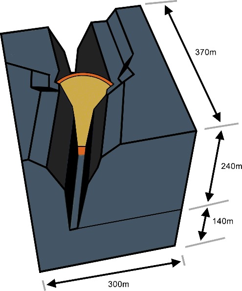
Table 2. Isotropic material properties of the dam and rock.
In the FEM, dead load (gravity loading), water load and two different routing temperatures (12, 14 °C) were considered. Water load up to 694 m (max level) was calculated with closed block joints up to 700 m (max grouting level).
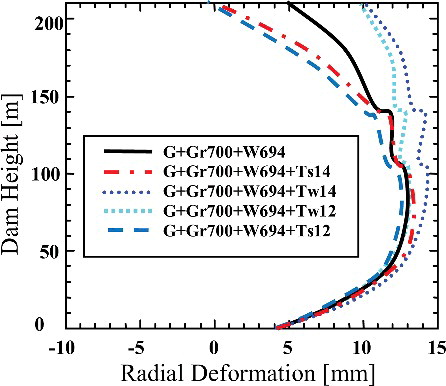
The computed deformations for different loading stages (gravity loading (G), grouting elevation (Gr), water load (w), ambient temperature for summer (Ts) and winter (Tw)) are given in (Mayer et al. Citation2012). As can be seen in the plot of , maximum and minimum deformations were computed for Tw = 14 °C and Ts = 12 °C, respectively. Also, maximum deformations for all cases are less than 10 mm at the upper side whereas this value reaches 15 mm at the middle of the dam.
Figure 3. Computed deformations for downstream open contact.
4. Geodetic deformation monitoring system
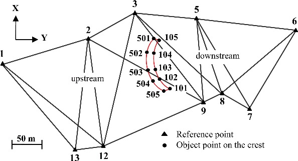
In order to determine the possible horizontal deformations, a micro-geodetic network consisting of 10 reference and 19 object points was established. illustrates the location of the reference points of the micro-geodetic network with respect to the dam crest.
Figure 4. Micro-geodetic horizontal deformation monitoring network and dam site.
All reference points are located on the stable terrain (bedrock) outside the dam's area, where deformation is not expected. These points are established as concrete geodetic pillar monuments, which are grounded on a rock outcrop, to avoid instrumental centring error. Each reference point has clear sights to at least three other reference points. The inter-distance between the reference points varies between 27 and 237 m. The location of the reference points was designed to observe each object point from a combination of at least three reference points and to detect horizontal displacement with millimetre level.
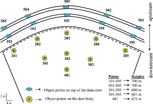
From the 19 object points, 10 are located along the crest dam (points 101–105 and points 501–505). As can be seen from , points 101–105 are established in the downstream area of the crest, whereas points 501–505 are established along the upstream side of the crest. There are two main reasons for establishing object points at both sides of the crest: first, for verification purposes of measured displacements obtained in the same cross section at opposite locations and, second, in order to ensure that adequate measurements are collected even if a number of object points are destroyed for whatever reason. These points are suitable for placing tribrach and reflector enabling direction, vertical angle and distance measurements from the reference points on both the downstream and upstream sides to enable accurate point fixing. The remaining nine object points (201–205, 301–303, 401) are located on the downstream side of the dam body and enable only horizontal direction and vertical angle measurements (). Also, in order to examine the magnitude of the displacements in the different parts of the dam, object points are established at different elevations (see ).
Figure 5. Schematic view of distribution of the object points on downstream side of the dam body and upstream--downstream sides of the crest of the dam.
The geodetic measurements undertaken in 03.01.2011 are regarded as being the reference period. Then, eight measurement campaigns were carried out until the reservoir water level reached 694 m of its full capacity. It is worth mentioning that at the first measurement campaign the reservoir level was 635.6 m height.
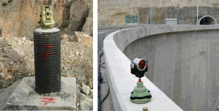
Horizontal direction measurements were carried out in four periods from each reference point whereas distance measurements were made at five independent orientations. The technical characteristics of the equipment and instruments used are given in . The total station and the reflector pair installed on a concrete pillar as well as the dam crest can be seen in . Geodetic measurements were initially executed by the State Water Works Administration (DSI-IVth Regional Directorates) staff and Selcuk University, Department of Geomatic Engineering, which were later carried out by DSI staff.
Table 3. Technical properties of geodetic instruments.
Figure 6. Total station on the reference point and prism on the crest.
5. Processing of geodetic observations and deformation analysis
The computational principle of the Conventional Deformation Analysis technique relies on coordinate difference comparisons obtained in a geodetic network between two different observation epochs (Caspary Citation1988). If they are rejected as expected movements by statistical tests, these differences are interpreted as being the “displacements” (Hekimoglu et al. Citation2010). In general, deformation analysis is carried out in three sequential steps: (Equation1(1) ) adjustment and outlier detection, (Equation2
(2) ) Global Congruency Test (GCT) and (Equation3
(3) ) localization procedure, if necessary, depending on the statistical results of the GCT.
In the first step, the monitoring network is adjusted as a free network for each epoch. The corresponding Gauss–Markov model for geodetic networks is given as follows (Caspary Citation1988; Hekimoglu et al. Citation2014):
(1)
(2)
(3)
(4) where A is the design matrix, x denotes the vector of estimated unknown parameters (point coordinates), P is the weights matrix, whereas l and v are the observations and residuals vectors, respectively;
is the pseudo-inverse, Qxx and Qvv are the cofactor matrices of the unknowns and residual vectors, respectively, s2 is the posteriori variance of the unit weight and f is the degree of freedom.
In this study, Pope's tests for outliers (Pope Citation1976), based on a-posteriori variance, have been adopted to detect outlying observation(s). Since the outlier detecting procedure was carried out just after the observation campaign, the detected outlier observation, if any, was immediately remeasured. A free network adjustment was then employed before applying the GCT.
In the second step, the GCT method is used to investigate whether there are any significant displacements between two measurement epochs or not. Let the displacement between two epochs be as follows:
(5) where x1 and x2 are the estimated coordinate vectors of each epoch. The null hypothesis Ho; E(d) = 0, which states that all object points are expected to have zero movement is tested against the alternative hypothesis Ha: E(d) ≠ 0.
Then, the GCT is calculated using the following equations (Pelzer Citation1985; Niemeier Citation1985):
(6)
(7)
(8)
(9) where
and
are the cofactor matrices of each epoch,
is the cofactor matrix of d,
is the pseudo-inverse of
, h is the rank of matrix Qdd,
denotes the estimated variance of d and T is called the test statistic. This value is compared to a value determined by the F (Fisher) distribution. If
then the null hypothesis is rejected. Thus, the difference in the coordinates between two epochs is interpreted as the result of an unexpected displacement. The next step is concerned with its localization (Hekimoglu et al. Citation2010). Localization is a procedure where the displaced points are statistically identified. There are many variations of localization methods used for deformation analysis: for instance, the S-transformation technique (Baarda Citation1973), the relative confidence ellipse method (Heck et al. Citation1977) and the implicit hypothesis method (Niemeier Citation1985). In this study, the S-transformation method was used to implement the localization procedure. More details regarding localization procedures can be found in Hekimoglu et al. (Citation2010).
6. Results and discussions
To determine the possible horizontal movements, each observation period was processed separately. Each observation period was adjusted by using the free network adjustment method. presents the root mean square (RMS) errors of all period measurements encountered in this study.
Table 4. RMS errors of the period measurements.
6.1. Reservoir level and concrete temperature
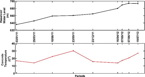
In addition to monitoring the structural behaviour of Ermenek Dam, the key environmental data parameters including reservoir water level and dam body temperature were monitored to assist in establishing dynamic load–displacement relationships. For this purpose, among other parameters, the reservoir water level and concrete temperature data were recorded daily. The reservoir water level and concrete temperature are given in . Specifically, concrete temperatures were measured using a thermometer embedded in the dam body at an elevation of 690 m. As can be seen from , reservoir water level starting from the reference period (03.01.2011) to the last period (19.07.2012) encountered was raised about 58 m, an increase of the order 10 cm/day. The concrete temperature has a seasonal fluctuation varying in the range between +14 and +30 °C.
Figure 7. Reservoir level and concrete temperature.
6.2. Assessment of absolute displacements
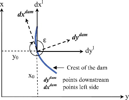
In order to compare the displacement results of the measurements with those computed from the FE modelling, the geodetically derived displacement vectors were translated into the dam coordinate system which is used in the FE analysis (). The displacements of each object point in the geodetic coordinate system were calculated using the following equation (Gikas & Sakellariou Citation2008b):
(10) where (dxl, dyl) expresses the displacement vector with respect to the reference period in the geodetic coordinate system. Specifically, i and o denote the number of periods and reference periods, respectively. Then, the displacements in the geodetic coordinate system were transformed into the dam coordinate system using the following equations:
(11) where dxdam and dydam express the tangential and radial displacements with respect to the dam coordinate system, respectively. Hereafter, for simplicity reasons, dxdam and dydam will be referred to as tangential and radial displacements, respectively. ϵ is the angle between the geodetic and dam coordinate systems, calculated based on three points on the crest (102, 103 and 104). EquationEquations 10
(10) and Equation11
(11) were applied for every object point to realize the 2D similarity transformation.
Figure 8. Transformation of the coordinate system of geodetic data.
– illustrate the absolute displacements of the object points in the radial and tangential directions. In these plots, the object points are grouped with respect to their corresponding vertical cross sections. Positive displacements indicate point movements towards the upstream and right-side directions for the radial and tangential components, respectively. In these plots, radial movements are larger than the tangential movements.
Figure 9. Radial and tangential displacements of the object points on the central cross section of the dam.
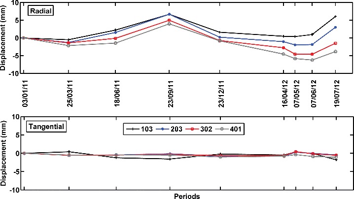
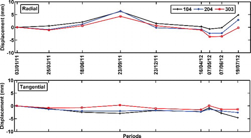
The largest apparent total displacement in the radial direction was experienced at point 103 at the middle of the dam, which reached nearly 7.5 mm between 03.01.2011 (the reference period) and 23.09.2011 (). However, the displacement in the tangential direction usually did not exceed ±2 mm for all object points. The difference between radial and tangential responses of the dam to reservoir water level and temperature change is due to construction geometry and load direction, among others. As can be seen from –, the time-series displacements exhibit both an oscillation component and a linear trend component. The oscillation component is most likely due to seasonal temperature changes, whereas the linear trend is because of linearly increasing reservoir water level. Also, the oscillation components of the displacement time series for each object point concerned looks similar in terms of magnitude and pattern, while the slope and magnitude of the linear components vary depending on their height. For example, the linear component is increasing for point 103 while it is decreasing for point 401. This observation indicates that the highest part of the dam is displaced in the upstream direction whereas the lower part of the dam moves towards the downstream direction.
Figure 10. Radial and tangential displacements of the object points between the centre and left-tail end of the dam.
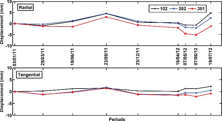
Figure 11. Radial and tangential displacements of the object points between the centre and right-tail end of the dam.
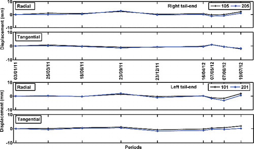
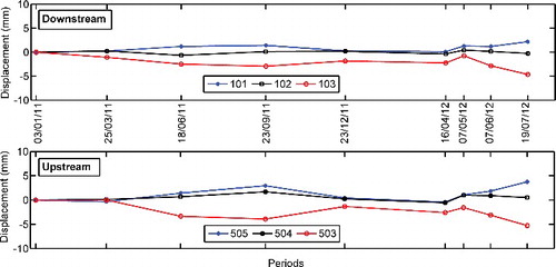
In addition, there is no significant movement found for right-tail and left-tail end points in both the radial and tangential directions (). The apparent displacement in both directions usually did not exceed ±2 mm for the object points (101, 201, 105, 205). This indicated that the left-tail and right-tail parts of the dam are very rigid.
Figure 12. Radial and tangential displacements of the object points on the right-tail and left-tail ends of the dam.
6.3. Decomposing seasonal temperature and linear reservoir level effects
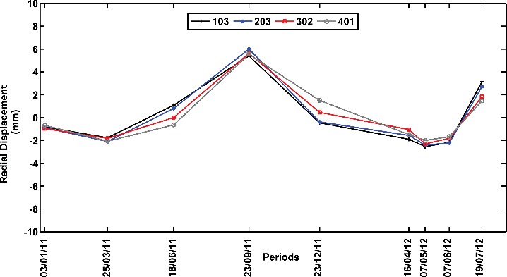
In Section 6.2, all object point movements were computed against the reference point locations, and thus the displacements obtained correspond to absolute movements. However, given the linear character of water level increases in the reservoir, it is possible to extract the temperature effect from total displacements. In order to examine the dam response to seasonal temperature variations, the linear trend in measured displacements was removed from each point independently. shows the de-trended radial displacement time series computed from their absolute values equivalent shown in . From this plot, it is evident that four object points located at different elevations demonstrate nearly the same response to seasonal temperature variations with small differences (0–2 mm). The correlation coefficient values obtained for the de-trended movement and concrete temperature are 91%, 93%, 90% and 86% for object points 103, 203, 302 and 401, respectively. These results suggest a strong relationship between the harmonic response of the dam and seasonal temperature fluctuation. The results indicate that a temperature change in dam material of the order of 16 °C can be responsible for about 8-mm displacement in the dam body (see the bottom plot of and the top plot of ).
Figure 13. Radial displacement of the object points on the central cross section of the dam after linear trend removed.
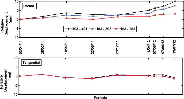
In order to further understand the mechanism of displacement response of the dam to water load, relative displacements of the object points 203, 302 and 401 with respect to object point 103 were calculated. Therefore, the movements caused due to seasonal temperature effects were mostly removed from the apparent displacements since the displacement response of all four object points to temperature variations is of the same amount. Thus, relative displacements contain mostly the water load response of the dam. As can be seen from , relative radial movements increase with time, whereas their patterns are more similar to the reservoir level increase. Correlation coefficients obtained between relative radial movements and the reservoir level increase are of the order of 93% for object points 103–401, 103–302 and 103–203. Particularly, relative radial displacement between object points 103 and 401 reached up to 10 mm for the time period the water level raised its maximum value. Conclusively, these results indicate that a 58-m rise of the reservoir water level produced a relative deformation of about 10 mm at the middle of the dam crest with respect to its basement (object point 401). As expected, there was no apparent linear correlation between relative tangential displacements and reservoir level. They contained only measurement noise.
Figure 14. Relative radial displacement of the object points along the central cross section of the dam.
6.4. Comparison between upstream and downstream crest points
As already mentioned, in addition to points located on the crest at the downstream side of the dam, there are points on the crest at the upstream side established as a backup in case certain points are destroyed or vandalized. Therefore, this subsection is devoted to compare the behaviour of object points 502, 503 and 504 sitting upstream with their pair equivalents (object points 102, 103 and 104) sitting downstream. Their radial and tangential displacements are given in and , respectively. From these plots, it is evident that the observed displacements for the upstream and downstream points are highly consistent with small differences between the orders of 1–2 mm. Such differences are very small and may reflect differences in the observation plan. Also, it is worth mentioning that backup points, especially for the locations for which maximum deformation is expected, are important to maintain monitoring without interruption. If conditions permit, a sufficient number of redundant (backup) points for certain locations on the structures should be established.
Figure 15. Radial displacement of the object points on upstream and downstream of the crest of the dam (102, 103, 104 corresponds 504, 503, 502, respectively).
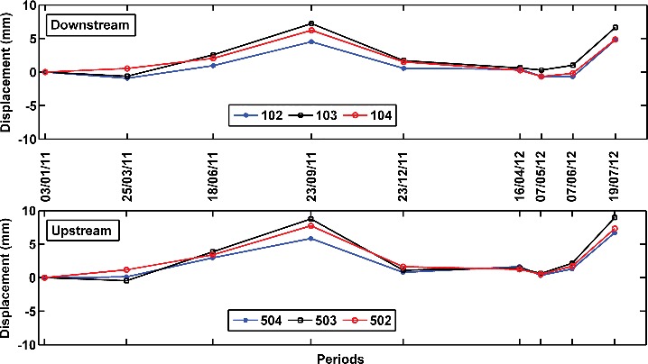
Figure 16. Tangential displacement of the object points on upstream and downstream of the crest of the dam (102, 103, 104 corresponds 504, 503, 502, respectively).
7. Conclusion
The main goal of this paper is to evaluate the dynamic behaviour of the Ermenek Dam during the first filling of reservoir. The results demonstrated that the absolute displacement time series exhibited both periodicity and a linear trend during the eight measurement periods. Maximum total displacement in the radial direction was experienced in the middle of the dam with a displacement amplitude reaching 7.5 mm, but statistically significant against random errors. Correlation analysis demonstrated that the periodicity and linear trend in the time series are related to seasonal concrete temperature fluctuations increasing linearly with reservoir level. The correlation between the steady harmonic response of the dam and seasonal temperature oscillation after removing the linear trend from the absolute displacement was very high. The data indicated that a change of about 16 °C in concrete temperature produced a deformation about 8 mm in the dam body. To investigate the effect of variations in reservoir water level on the relative displacement response of the dam, relative displacements between four object points at the central cross section were calculated. The results obtained showed a high correlation between relative displacement response of the dam and reservoir water load. Also, data indicated that an increase of about 58 m in reservoir water level produced about 10 mm displacement in the dam body.
Besides the geodetic measurements, possible radial deformations were computed using FEM analyses. According to the numerical modelling, maximum radial displacements were 10 mm occurring in the highest part of the dam. The computed values were highly compatible with their measured corresponding values considering the measurement noise. This indicated that the structural behaviour of the Ermenek Dam was normal during the first filling period.
This study also demonstrated that the micro-geodetic network solution can detect very efficiently the structural response of a concrete arch dam, which is very stiff, even when the harmonic and linear displacements in the horizontal direction are in the range of 1–10 mm level.
In future research, the relation between the structural response of the dam and the main loads, such as hydrostatic and thermal loads, will be investigated in detail based on the daily data obtained from geotechnical sensors. Hence, both the absolute and relative movements of the dam can be evaluated based on the geodetic and geotechnical data, respectively.
Acknowledgements
The Turkish General Directorate of State Hydrologic Works (DSI), the 4th Regional Directorate Konya and staff working on the Ermenek Dam are thanked for providing unpublished data. The authors are very grateful to anonymous reviewers for their constructive comments. We would like to thank Prof Cevat Inal for his support and encouragement.
Disclosure statement
No potential conflict of interest was reported by the authors.
References
- Aguilera DG, Lahoz JG, Sanchez J. 2008. A new approach for structural monitoring of large dams with a three-dimensional laser scanner. Sensors. 8:5866–5883.
- Baarda W. 1973. S-transformation and criterion matrices. Taylor & Francis.>Delft: Publications on Geodesy, New Series 5(1).
- Bayrak T. 2008. Verifying pressure of water on dams, a case study. Sensors. 8:5376–5385.
- Caspary WF. 1988. Concepts of network and deformation analysis. Monograph 11, 2nd corrected impression. Kensington: Taylor & Francis; p. 183.
- Ehiorobo J, Ehigiator RI. 2011. Monitoring for horizontal movement in an earth dam using differential GPS. J Emerg Trends Eng Appl Sci. 2:908–913.
- Gikas V, Sakellariou M. 2008a. Settlement analysis of the Mornos earth dam (Greece): evidence from numerical modeling and geodetic monitoring. Eng Struct. 30:3074–3081.
- Gikas V, Sakellariou M. 2008b. Horizontal deflection analysis of a large earthen dam by means of geodetic and geotechnical methods. In: 13th FIG sysmposium on deformation measurement and analysis. Lisbon (Portugal): Taylor & Francis.
- Guler G, Kilic H, Hosbas G, Ozaydın K. 2006. Evaluation of the movements of the dam embankments by means of geodetic and geotechnical methods. J Surv Eng. 132:31–39.
- Heck B, Kuntz E, Meier-Hirmer B. 1977. Deformationsanalyse mittels relativer Fehlerellipsen. Allg Vermessungs Nachr. 84:78–87.
- Hekimoglu S, Erenoglu RC. 2009. New method for outlier diagnostics in linear regression. J Surv Eng. 135:85–89.
- Hekimoglu S, Erdogan B, Butterworth S. 2010. Increasing the efficacy of the conventional deformation analysis methods: alternative strategy. J Surv Eng. 136:53–62.
- Hekimoglu S, Erdogan B, Soycan M, Durdag UM. 2014. Univariate approach for detecting outliers in geodetic networks. J Surv Eng. 140:04014006(1–8).
- Hibbitt D, Karlsson B, Sorensen P. 2008. ABAQUS. Version 6.8. RI: Taylor & Francis.
- Kalkan Y. 2014. Geodetic deformation monitoring of Ataturk dam in Turkey. Arab J Geosci. 7:397–405.
- Kuang S. 1996. Geodetic network analysis and optimal design: concepts and applications. Chelsea (MI) Taylor & Francis.
- Mayer B, Güven S, Linortner J, Kronberger O. 2012. Dam monitoring during impounding. Taylor & Francis. (Evaluation report no:10 (unpublished report)).
- Niemeier W.1985. Deformations analyse. In: H. Pelzer, editor. Geodaetische netze in landes und ingenieurvermessung II. Stuttgart: Taylor & Francis; p. 559–623.
- Ogaja C. 2002. A framework in support of structural monitoring by real time kinematic GPS and multi-sensor data [dissertation]. Taylor & Francis; p. 192.
- Parkinson BW, Spilker Jr. 1996. Global positioning system: theory and applications (Vol. 1). Washington (DC): Taylor & Francis; p. 793.
- Pelzer H. 1985. Geodatische netze in lands und ingenieurvermessung II. Stuttgart: Taylor & Francis.
- Pope A. 1976. The statistics of residuals and the detection of outliers. Rockville (MD): Taylor & Francis. (Technical Rep. No. NOS 65 NGS 1).
- Pytharouli SI, Stiros SC. 2005. Ladon dam (Greece) deformation and reservoir level fluctuations: evidence for a causative relationship from the spectral analysis of a geodetic monitoring record. 27:361–370.
- QingWen R, Qiang L, Shuang L. 2012. Research advance in failure risk and local strength failure for high arch dams. Chin Sci Bull. 57:4672–4682.
- De Sortis A, Paoliani P. 2007. Statistical analysis and structural identification in concrete dam monitoring. Eng Struct. 29:110–120.