
 ?Mathematical formulae have been encoded as MathML and are displayed in this HTML version using MathJax in order to improve their display. Uncheck the box to turn MathJax off. This feature requires Javascript. Click on a formula to zoom.
Abstract
Coal spontaneous combustion (CSC) in gob causes notorious safety issues to workers, especially during withdrawal period. Withdrawal period was normally divided into three stages (initial stage, expanding back channel stage and equipment returning stage) when evaluating and preventing the risk of CSC. This study first analyzed the characteristics of ventilation system at each stage, such as oxidized zone movement, local fire wind pressure and air leakage. Then, principles and specialized measurements were applied to minimize the ranges and effects of CSC in gob. In detail, this includes reducing the total air volume flow of mining face in initial stage, adding windscreen in outlet way and local fan in inlet way to increase the pressure of working face, and lowering external air leakage. Considering the working face ventilation area shrinks at equipment returning stage, keeping it bigger than windscreen’s areas can help to reduce air leakage. Further, foamed gel was grouted into gob to narrow and stop the moving forward of oxidized zone. Field application was applied in Zhang Shuang-lou coal mine. Findings of these studies could be used in other coal mine with similar conditions during withdrawal period.
1. Introduction
Coal is currently the most commonly used energy source in the world (Jennifer et al. Citation2018; Li et al. Citation2018; Peña et al. Citation2018; Reisen et al. Citation2017; Shi et al. Citation2018). According to state statistics, coal, with 3.433 billion tons production, accounts for 61.83% of disposable energy consumption in 2016, far more than 18.9% of petroleum consumption (Ren et al. Citation2009; Wang Citation2010; Yu Citation2014). However, lethal disasters exist in the process of mining. Coal spontaneous combustion (CSC) is among the leading causes of tragedies, such as gas and coal dust explosion and mortality of workers, and the potential economic loss and environmental pollution (Ren and Wang Citation2012; Ren et al. Citation2016; Bhattacharjee et al. Citation2012). In March 2013, two continuous gas explosions triggered by CSC in gob killed 53 people at Babao Coal Mine in Jilin northeast province of China. Incomplete statistics from 2001 to 2014 suggested that there were about 32 cases of gas explosion or fire disasters underground Coal Mines resulting from CSC that led up to 614 death (Zhou Citation2012; Wang et al. Citation2014). The Chinese government and research institutes have devoted considerable financial and material efforts on CSC suppression in gobs (Song and Hao Citation2008; Ye et al. Citation2017).
Withdrawal of working face is one of the key and must processes for coal mines (Hao et al. Citation2012; Wen et al. Citation2014). Equipment, such as shearer, scraper conveyor, crusher, hydraulic support and other devices, is required to be returned for maintenance after finishing working face, and recycled for the next working face. In China, a 150 m long working face, the total value is near to ¥0.15 billion ($23.2 million), which accounts for an important part of coal mine interest. During withdrawal, CSC, roof collapse, gas transfinite and ventilation disorder are the four high-triggered hazards. On 6 January 2018, a worker was killed by a sudden broken wire rope during this withdrawal period in Hai Shiwan coal mine Gansu province. Qinyuan coal mine in Shanxi province had sealed four working faces because of the CSC occurring withdrawal period and hydraulic supports not able to get back, which resulted in millions loss in 2015–2016.
Literature reviews indicated that majority studies focused on implementation of safety strategy during the process of mining (Liu et al. Citation2014; Jin et al. Citation2015; Li et al. Citation2016; Zhang et al. Citation2016). However, withdrawal period faced the highest chance of CSC in gobs and was much more complicated due to unstable ventilation system and longtime stopping (Ren et al. Citation2016). Further, with the breakthrough of deep mining, high ground stress and geothermal are more favourable for CSC events. XIE et al applied local ventilation flow control to prevent the diffusion of CO during withdrawal period, but they ignored the instability of ventilation system and its limitation in fire prevention (Xie et al. Citation2002). Chen and Hou presented comprehensive methods to prevent CSC in easy-ignition coal seam gobs, but the working face was single seam and they did not analyze how air leakage affected the developing of CSC (Chen and Hou Citation2012). Liu and Qin (Citation2017a, Citation2017b) indicated that CSC in gob was the result of interaction of multi-physical fields, including air seepage and heat transfer. Among those factors, ventilation system plays the most significant role, because the stability of ventilation system is the premise for safety mining. Some researches divided the gob into three zones, where the area with the risk of CSC is identified as ‘oxidized zone’, but it is not possible to locate an accurate fire position for prevention (Ren et al. Citation2015; Cheng et al. Citation2017; Wang et al. Citation2014). In summary, there are still some severe issues need to be considered on CSC prevention during withdrawal period, for example the integrated technique to follow. In addition, challenges still exist in stabilizing the ventilation system and control CSC. As a result, the main objective of our study is to identify the ventilation change and choose a feasible way to control CSC during withdrawal period. The findings probably could be used in other coal mine under similar conditions during withdrawal period.
In this study, we analyzed the causes of CSC during withdrawal period. The whole process of withdrawal was divided into three parts: initial stage, expanding back channel stage and equipment returning stage. Ventilation changing laws corresponding to the three steps were presented. Meanwhile, risk area of gob was narrowed within 20 m back the working face. Foamed gel technology was used for CSC prevention. Field application was implemented in Zhang Shuang-lou Coal Mine in Xuzhou Jiangsu province.
2. Characters of CSC during withdrawal period
2.1. Causes for CSC
Coal seams with spontaneous combustion tendency in developing into self-ignition when gathering four factors: plenty of broken coal; continuous air supplying; heat storage and enough time for coal’s oxidation (Gulyaeva and Arikan Citation2017). Causes for CSC during withdrawal period are as .
Table 1. CSC grade during withdrawal period.
Table 2. Explanation of branches.
First, at the final time of mining, top coal, around 50 m, is not caved to keep the roof stable, resulting in plenty of coal in gob ignition resource. Second, it takes a long time to excavate returning path and return equipment, which provides sufficient time for coal oxidation. Further, the heat generated by oxidation accumulates and reinforces coal oxidation in return. At last, ventilation system may disorder with roof collapse caused by hydraulic supports moving. According to our empirical study, CSC in gob could be set three grades based on withdrawing time (T) and spontaneous combustion period (t) as .
We should predict the process of CSC and take specific methods according to the grades. The most affected aspects are ventilation system and CSC areas.
2.2. Movement of oxidized zone
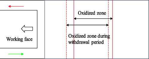
Gob is generally divided into three zones based on O2 concentration (ϕ). They are non-spontaneous combustion zone (ϕ > 15%), oxidized zone (15% > ϕ > 5%) and asphyxiation zone (ϕ < 5%). Oxidized zone is the most dangerous area for possible developing CSC (Wang Citation2010; Zhang et al. Citation1998; Mishra et al. Citation2011).The ranges of oxidized zone vary with gobs, but we assume that it is constant for a given gob. However, oxidized zone would move forward if the working face stopped a long time, which make it worse for CSC control and prevention.
Permeability distribution of gob determines the flow-diffusion law of oxygen, affects the range of oxidized zone, and further applies to the oxidation exothermic of coal, and finally determines the distribution of temperature field.
The relationship between broken expansion coefficient α and porosity k of gob is:
(1)
(1)
Which means k and α are positive correlation (Zhang et al. Citation2012).
Based on the previous studies, α can be expressed as EquationEquation 2(2)
(2) :
(2)
(2)
The expression of permeability and porosity in gob is as EquationEquation 3(3)
(3) :
(3)
(3)
Where: α0: The minimum broken expansion coefficient. λ: Correction coefficient. τ: Time of withdrawal. DP: The average diameter distribution of coal and rock in gob; n: Permeability of gob.
From EquationEquations 1(1)
(1) and Equation2
(2)
(2) , we know that when the porosity is small, permeability decreases with porosity (Peña et al. Citation2017; Oliveira et al. Citation2018; Zhou Citation2017). O2 distribution in gob is influenced by porosity. Air leakage velocity is affected by permeability. Moreover, CSC in gob is a result of oxidation of coal residue under suitable air leakage velocity (vair) and oxygen concentration (ϕ). Thus the oxidized zone in gob shrinks and moves forward as the reduction of air leakage velocity and O2 concentration (). It is confirmed by field applications.
Figure 1. Oxidized zone movement during withdrawal period.
2.3. Ventilation system changing laws
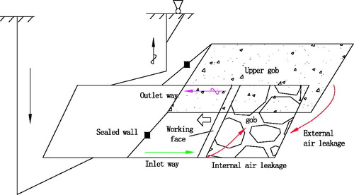
2.3.1. Air leakage
In ventilation system (), the most important factor is air leakage (ΔQ) in gob, including external leakage (ΔQE) and internal air leakage (ΔQI) (EquationEquation 4(4)
(4) ).
(4)
(4)
Figure 2. Ventilation system of working face.
In ventilation system, air volume follows EquationEquation 5(5)
(5) :
(5)
(5)
Where: Q, intake air volume; QW, air volume in working face.
Air leakage varies with withdrawal periods.
Initial stage: the airflow (Q) is smaller than in process of mining, so air leakage is small.
Expanding back channel stage: Ventilation resistance decreases significantly in the second stage. Based on ventilation resistance law, it can be easily deduced that QW increases. As Q is constant, ΔQI would decrease correspondingly. However, the reduction of total pressure in working area leads to the increase of ΔQE, which promotes the risk of CSC in gobs.
Equipment returning stage: Collapsed coal and rock are silted the working face at this stage, which increase the ventilation resistance and pressure of working area. As a result, ΔQE would decrease, ΔQI increases on the contrary, which leads to severe CSC risk.
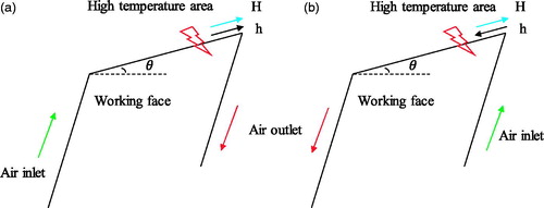
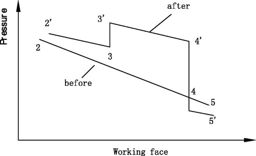
2.3.2. Local fire wind pressure
Local fire wind pressure is another potential disaster during withdrawal period. Shown as , there are two ways for ventilation in declined working face: upward and downward ventilation.
Figure 3. Two ventilation forms in working face. (a) Upward ventilation; (b) Downward ventilation.
In inclined roadway, Local fire wind pressure can be calculated as EquationEquations 6(6)
(6) and Equation7
(7)
(7) :
(6)
(6)
(7)
(7)
Where: H: Local fire wind pressure, Pa. g: Gravitational acceleration, m/s2. z: Height difference, m. ρi: Air density at position , kg/m3. h: Ventilation pressure, Pa. θ: Angle, °. Δh: Pressure difference, Pa.
Pressure difference determines the flow direction, and it will not be changed in upward ventilation by local fire wind pressure. However, for downward ventilation, if Δh < 0, flow reversal would happen and the mine ventilation system will be disrupted.
To minimize the influences from local fire wind pressure, lower air leakage, and reduce the risk of CSC, pressure balancing technology was used. Foamed gel was also grouted into gob to seal air channel and stop the movement of the oxidized zone.
3. Pressure balancing technology and foamed gel technology
3.1. Theoretical analyses based on the process of withdrawal
Ventilation system of mining face is simplified as . The explanations of branches are shown in Table 2. Premises are follows:
Figure 4. Diagram of ventilation network.
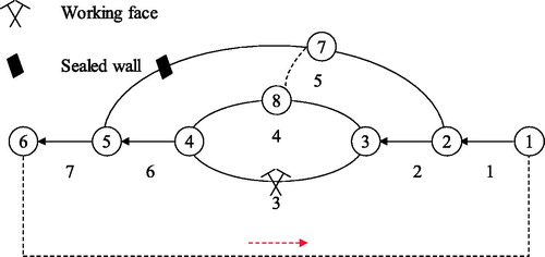
External air leakage channel is regarded as a ventilation branch;
Mining face is divided into two parallel branches.
Based on ventilation resistance law, we have:
(8)
(8)
In , the air volume matches EquationEquation 9(9)
(9) :
(9)
(9)
According to ventilation resistance law:
(10)
(10)
Where Qi (i = 1, 2, 3…7) represents air flow volume of each branch. Δh5: Pressure difference between upper gob and gob.
3.1.1. Expanding back channel stage
As described above, external air leakage will increase in this stage, which aggravates the risk of CSC in gobs of mining face.
To reduce the external air leakage is to add pressure of working face. So a regulation windscreen was installed in branch 6, and a local fan was installed in branch 2. Pressure distributions in working face are shown in .
Figure 5. Pressure changes in mining face.
3.1.2. Equipment returning stage
In this stage, wooden cribs were used temporarily for roof supporting which can lower the ventilation areas in branch 3, and its ventilation resistance increased while branch 4 kept constant. Air flow differences of branch 2, 3 and 4 matched with EquationEquation 11(11)
(11) , which indicate that internal air leakage increased with the ventilation in branch 3.
(11)
(11)
To balance the ventilation system, we took following two measures:
Expand ventilation areas of branch 3.
Use regulation windscreen in branch 6 to enhance the pressure of working face.
The key point is how to control the ventilation areas of branch 3 and 6.
After taking i and ii measures, air flow volume changes as EquationEquation 12(12)
(12) :
(12)
(12)
The reduction of ventilation resistance between node 2 and 5 (whole working face) is caused only by measure i:
(13)
(13)
After taking measure ii, the ventilation resistance increases between node 2 and 5:
(14)
(14)
where: R2–5 is the original ventilation resistance before taking measure i; R2–5’ is the ventilation resistance after taking measure i; ΔR2–5’ is the difference value; R2–5’’ is the ventilation resistance after taking measure ii; ΔR2–5’’ is the difference value.
Air leakage reduction can be explained by following expressions:
ΔQ4 <0, represents the reduction of internal air leakage.
ΔQ5 <0, represents the reduction of external air leakage.
Reducing internal air leakage is easily achieved by expanding the ventilation area of branch 3, just as described in measure i.
For ΔQ5 <0, we should keep:
(15)
(15)
Ventilation resistances of each branch match EquationEquation 16(16)
(16) :
(16)
(16)
Where: Ri is the ventilation resistance of each branch; Ri’ and R’’ represent the ventilation resistance of each branch after taking measures i and ii, i = 1,2,3…7.
From EquationEquation 16(16)
(16) , we get:
(17)
(17)
Combine the EquationEquations 15(15)
(15) and Equation17
(17)
(17) :
(18)
(18)
Where, ΔR3’<0. And
(19)
(19)
If ΔR7’/|ΔR3’|>1, EquationEquation 20(20)
(20) is correct:
(20)
(20)
Then ΔQ5 < 0.
In field application of withdrawal process, η = ΔR7’/|ΔR3’| could be a standard that indicates the change of external air leakage, there are two situations:
(21)
(21)
In ventilation system, R = αLU/S3.
Where: R: Friction, (kg/m7); α: Friction factor, (kg/m3); L: Length of roadway, (m); U: Circumference of roadway, (m); S: Ventilation area of roadway, (m2).
For an intact roadway in coal mine, S is the easiest factor to change for regulating wind pressure and air flow in field application.
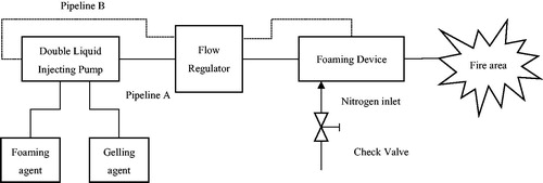
3.2. Parameters of foamed gel
Foamed gel was used to seal air leakage channel and prevent the moving of oxidized zone. This material consists of free liquid, gel particles, and foam, which integrates the performance of both foam and gel on fire control. Gel is transported into the interspace of gobs by taking foam as a carrier, which has excellent performances of holding water, spraying, covering, and sealing air leakage channel.
Its field application flow chart was shown as . The operating procedures are as follows. First, mixture with additive A/B is pumped proportion to the pipeline, flowing through a flow regulation windscreen to foam device. High-speed jet flow forms when the premixed solution flows through the nozzle in the foaming device. Meanwhile, nitrogen is injected into the device through nitrogen inlet, and mixes with the liquid jet generating a large amount of foamed gel.
Figure 6. Flow chart of foamed gel application.
4. Field application and effect
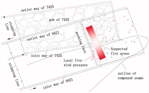
4.1. Developing of CSC
Field application was conducted in Zhang Shuang-lou Coal Mine, Jiangsu province in China. The roadway layout, downward ventilation system and fire areas of mining face are shown in . Average coal seam thickness and length of fully mechanized 9421 working face, down to 7425 mining face, are 6.4 m and 320 m. Its average inclination angle is 25°, which is the main cause of slowing mining speed. Igneous rock, another induced factor of CSC, with areas of 478 m2, intrudes the partial roof of 9421 working face.
Figure 7. Layout of roadway and coal fire areas.
The development of CSC was divided into four stages:
The mining distance was only 1.8m per month in 12/2013, which provided sufficient time for coal oxidation and heat producing. Grouting liquid CO2 in sealed gobs was taken to control the risk, which has limited effect.
On April 2014, CO concentration increased straightly to 720 × 10−6 in the rear of supports. Air leakage exacerbated CSC risk.
9421 mining face was unsealed in May 2015, but it was stopped again due to the restriction of igneous rock, which lowered the mining velocity to 4m/s in one month and aggravated the coal self-heating. The mining face was sealed and grouted liquid CO2 again.
As the high temperature areas were not eliminated entirely due to the insufficient sealing time, CO concentration increased fast to 700 × 10−6 after the second unseal of 9421 mining face.
In the application process, local fire wind pressure occurred near upper corner, the velocity of air flow was near 0.1m/s, opposite to original flow direction, which reflected that CSC endangered working face severely.
4.2. Application of pressure balancing technology and effects
Based on above analyses, following measures were then used:
Expanding back channel stage: install windscreen in outlet way and local fan in inlet way to reduce external air leakage.
Equipment returning stage: First, clean working face to add ventilation areas. Second, based on the first stage, keep local fan’s working conditions constant, and regulate windscreen step by step. To guarantee η > 1 according to EquationEquation 21
(21)
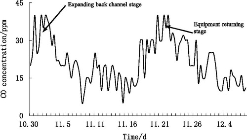
The effect after using CFA was evaluated by CO concentration shown in .
Figure 8. CO concentration in 9421 outlet way.
4.3. Application of foamed gel
The arrangement of high level boreholes was shown in . There were two rows of boreholes, covering the areas of suspected fire areas. The inner diameter of borehole was 75 mm and the final positions were about 10 m and 20 m away from hydraulic support. are parameters of holes.
Figure 9. High level boreholes arrangement for grouting foamed gel.
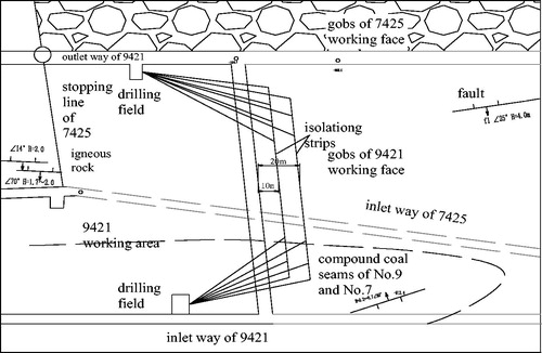
Table 3. High level boreholes parameters.
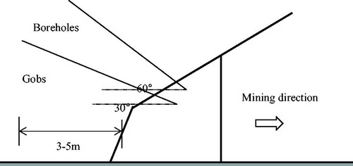
The broken rock in gobs gradually compacted under the influence of surrounding rock pressure, and the oxidation space spread from the deep area to the shallow, which caused severe fire risk. To prevent and minimize the damage of coal fire, additional boreholes were installed. Their final borehole position was 0.5–1 m down the coal seam roof, and about 3–5 m reared to the liquid supports. The total number was 15, and the diameter of borehole was 42 mm ().
Figure 10. Inter-rack boreholes arrangement.
Two isolating strips were formed 10 m and 20 m back to the support after grouting foamed gel. The CO concentration in 9421 working face fell from 400 × 10−6 to 50 × 10−6 in about 5 days after grouting foamed gel. This working face was withdrawn safely eventually.
5. Conclusion
Coal spontaneous combustion is a main threat to the safety of workers during equipment withdrawal period in coal mines. To prevent this risk, comprehensive methods including pressure balancing and foamed gel were used to suppress coal fire hazard based on ventilation system analyses. Findings of this study could be used in other coal mines with similar conditions. The main findings include:
Withdrawal process can be divided into three stages: initial stage, expanding back channel stage and equipment returning stage. Each stage has own features on ventilation system, which influences CSC and CO distribution.
The movement of oxidized zone and local fire wind pressure were two potential disasters during withdrawal period. Minimizing the destruction ranges can control ventilation system. In expanding back channel stage, windscreen and local fan were installed in outlet way and inlet way to reduce external air leakage. In equipment returning stage, standard of
To prevent the moving of oxidized zone, foamed gel was used to seal air leakage channel and cool high fire zones. Foamed gel integrated the performance of both foam and gel, and consisted of free liquid, gel particles, and foam. Two rows of drillings were arranged for grouting foamed gel, which could form isolation strip in gobs.
Acknowledgements
The authors would like to express special thanks to the editor and reviewers for their suggestions and comments.
Disclosure statement
No potential conflict of interest was reported by the authors.
References
- Bhattacharjee S, Roy P, Ghosh S, Misra S, Obaidat MS. 2012. Wireless sensor network-based fire detection, alarming, monitoring and prevention system for Bord-and-Pillar coal mines. J Syst Software. 85(3):571–581.
- Chen A, Hou SH. 2012. Comprehensive fire prevention and control technology for fully mechanized top coal caving mining face in easy spontaneous combustion seam during face equipment withdrawn period. Coal Sci Technol. 9:45–47 + 51.
- Cheng WM, Hu XM, Xie J, Zhao YY. 2017. An intelligent gel designed to control the spontaneous combustion of coal: Fire prevention and extinguishing properties. Fuel. 210:826–835.
- Gulyaeva T, Arikan F. 2017. Statistical discrimination of global post-seismic ionosphere effects under geomagnetic quiet and storm conditions. Geomat Natural Hazard Risk. 8(2):509–524.
- Hao MH, Wei ZY, Lu GL. 2012. Study on rational ventilation and fire prevention technology of fully mechanized top coal caving mining face during powered supports removing. Coal Sci Technol. 6:62–65.
- Jennifer MKO, Erika RN, Max LH, James CH, Mark AE, Joseph E, et al. 2018. Gas emissions, tars, and secondary minerals at the Ruth Mullins and tiptop coal mine fires. Int J Coal Geol. 195:304–316.
- Jin YF, Guo J, Wen H. 2015. Experimental study on the high temperature lean oxygen oxidation combustion characteristic parameters of coal spontaneous combustion. J China Coal Soc. 40(3):596–602.
- Li L, Chen JC, Jiang DY. 2016. Experimental study on temporal variation of high temperature region and index gas of coal spontaneous combustion. J China Coal Soc. 41(2):444–450.
- Li L, Qin B, Ma D, Zhuo H, Liang H, Gao A. 2018. Unique spatial methane distribution caused by spontaneous coal combustion in coal mine goafs: an experimental study. Process Safe Environ Protect. 116:199–207.
- Liu W, Qin Y. 2017a. A quantitative approach to evaluate risks of spontaneous combustion in longwall gobs based on CO emissions at upper corner. Fuel. 210:359–370.
- Liu W, Qin YP, Yang XB. 2014. Experimental study for impact of volatile matter on spontaneous combustion characteristics of coal. J China Coal Soc. 39(5):891–896.
- Liu W, Qin YP. 2017b. Multi-physics coupling model of coal spontaneous combustion in longwall gob area based on moving coordinates. Fuel. 188:553–566.
- Mishra RK, Bahuguna PP, Singh VK. 2011. Detection of coal mine fire in Jharia coal field using landsat-7 ETM + data. Int J Coal Geol. 86(1):73–78.
- Oliveira MLS, da Boit K, Pacheco F, Teixeira EC, Schneider IL, Crissien TJ, Pinto DC, Oyaga RM, Silva LFO. 2018. Multifaceted processes controlling the distribution of hazardous compounds in the spontaneous combustion of coal and the effect of these compounds on human health. Environ Res. 160:562–567.
- Peña B, Bartolomé C, Gil A. 2017. Analysis of thermal resistance evolution of ash deposits during co-firing of coal with biomass and coal mine waste residues. Fuel. 194:357–367.
- Peña B, Pallarés J, Bartolomé C, Herce C. 2018. Experimental study on the effects of co-firing coal mine waste residues with coal in PF swirl burners. Energy. 157:45–53.
- Reisen F, Gillett R, Choi J, Fisher G, Torre P. 2017. Characteristics of an open-cut coal mine fire pollution event. Atmos Environ. 151:140.
- Ren WX, Guo Q, Wang ZF. 2016. Application of foam-gel technology for coal spontaneous combustion suppression in coal mines. Nat Hazards. 84(2):1207–1218.
- Ren WX, Guo Q, Zuo BZ, Wang ZF. 2016. Design and application of device to add powdered gelling agent to pipeline system for fire prevention in coal mines. J Loss Prevent Process Indus. 41:147–153.
- Ren WX, Wang DM. 2012. A new method for reducing the prevalence of pneumoconiosis among coal miners: foam technology for dust control. J. Occup. Environ. Hyg. 9(4):D77–D83.
- Ren WX, Wang ZF, Guo Q. 2015. Application of foam-gel technique to control co exposure generated during spontaneous combustion of coal in coal mines. J. Occup. Environ. Hyg. 1545:9624.
- Ren WX, Wu BW, Wang DM. 2009. Study on the fire prevention technology of high gassy and easy spontaneous combustion super large underhand mining face. J Mining Safe Eng. 26(2):198–202.
- Shi Q, Qin B, Liang H, Gao Y, Bi Q, Qu B. 2018. Effects of igneous intrusions on the structure and spontaneous combustion propensity of coal: a case study of bituminous coal in daxing mine, China. Fuel. 216:181–189.
- Song LS, Hao YX. 2008. Comprehensive fire prevention and control technology during dismantling supports in fully-mechanized top coal caving face. J Xi’an Univ Sci Technol. 4:634–637.
- Wang DM. 2010. Mine Fires. Xuzhou: China University of Mining & Technology Press.
- Wang DM, Xin HH, Qi XY, Dou GL, Zhong XX. 2014. Mechanism and relationship of elementary reaction in spontaneous combustion of coal: the coal oxidation kinetics theory and application. J China Coal Soc. 39(8):1667–1674.
- Wen H, Cheng B, Zhai XW. 2014. Technology of spontaneous combustion prevention and control during withdrawing period in lower layered coal mining face. Coal Sci Technol. 4:54–56 + 87.
- Xie H, Chun Y, Liu Z, Cheng L. 2002. Drawing back hydraulic powered support from coal mining face on mine fire with local ventilation flow control. Coal Sci Technol. 11:26–28.
- Ye Q, Wang GGX, Jia Z, Zheng C. 2017. Experimental study on the influence of wall heat effect on gas explosion and its propagation. Appl Thermal Eng. 118:392–397.
- Yu T. 2014. Control mechanism and technology for integrated disaster of gas and coal spontaneous combustion in gob. Hefei: University of Science and Technology of China; pp. 9–21.
- Zhang C, Ti ZY, Li ZX. 2012. Loading stress field of goaf and the coupling with other fields. J Yangtze River Sci Res Inst. 29(3):50–54.
- Zhang RL, Yang YL, Ma ZL. 1998. Computer simulation in spontaneous-combustion gob’s air flowing field, temperature field and heat-pressure field. J Jiaozuo Inst Technol. 17(4):253–257.
- Zhang Y, Lim S, Sharples JJ. 2016. Modelling spatial patterns of wildfire occurrence in south-eastern Australia. Geomat Natural Hazard Risk. 7(6):1800–1816.
- Zhou FB. 2012. Study on the coexistence of gas and coal spontaneous combustion (I): disaster mechanism. J China Coal Soc. 37(5):843–849.
- Zhou PL. 2017. Research on the spatiotemporal evolvement of coal oxidation heating laws in gob. Xuzhou: University of Science and Technology Beijing.