
 ?Mathematical formulae have been encoded as MathML and are displayed in this HTML version using MathJax in order to improve their display. Uncheck the box to turn MathJax off. This feature requires Javascript. Click on a formula to zoom.
Abstract
Water inrush in mine is one of the most common hazards in the mining industry. To solve the problem of rescue route planning during a mine water inrush hazard, a dynamic rescue route planning method based on a 3 D network is proposed. First, the basic elements in the 3 D network model of the mine roadway are abstractly described, furthermore, the weights of edges, the topological connectivity of the elements, and the data structure of the network are defined. Then, the Dijkstra algorithm and the Breadth-first search algorithm are combined to implement the best rescue search route and return route planning based on the 3 D network model. Finally, the dynamic rescue route planning is simulated in 3 D virtual spatial scenario of a real mine. The factors such as topological connectivity of the elements, real-time water level, and slope of the mine roadways are considered in the process of rescue route planning, as the rescue route is adjusted dynamically according to the actual situations. This method proposed can provide powerful decision support for mine water inrush hazard rescue.
1. Introduction
With the expansion of mining scale, the mine roadways in the mine are getting longer and longer, the layouts in the mine roadways are more complicated, therefore the mine roadways gradually become a complex 3 D (three-dimensional) network [1-4] (Xu and Gong Citation2011; Wu, Lei, et al. Citation2013; Cui Citation2015; Dash, Bhattacharjee, and Paul Citation2016). Water inrush is one of the most common hazards in mines and results from hydrogeological factors (Wu, Zhou, et al. Citation2009; Ma and Zhang Citation2012). The flooding of the water in the mine roadways is a gradual process during water inrush. The water flows from the water inrush point into the mine roadways, then flows into the bottom along the mine roadways, and then the water level rises gradually from the bottom until it reaches equilibrium (Yao et al. Citation2011; Wu, Lei, et al. Citation2013; Wu et al. Citation2016; Qi et al. Citation2017). At this time, the rational formulation of rescue route plan is directly related to the life safety of the people working in the mine roadways. Therefore, rescue route plan is an important research subject in mine safety (Sheu Citation2007; Jalali and Noroozi Citation2009; Yuan and Wang Citation2009; Şalap, Karslıoğlu, and Demirel Citation2009; He et al. Citation2019).
In previous research within the field of mine safety, the concept of equivalent length is introduced to measure the weights of edges in the network (Wang Citation2017), but a method to determine the weights of various factors affecting the capacity of mine roadways in the rescue route planning during the water inrush hazard is not described in detail in the research (Fang et al. Citation2011; Wu, Zhou, et al. Citation2009; Wang Citation2017). However, the weights of some important factors, such as real-time water level, and slope of mine roadways, should be considered while the rescue route is being planned (Dong et al. Citation2018).
Dijkstra algorithm (Huang Citation2017) or its improved variants are the most popular approach used in the rescue route planning in previous research (Cheng, Zhang, and Li Citation2014; Zhao et al. Citation2015; Zhao and Zong Citation2015; Likaj and Shala Citation2017), however, seldom is the dynamic variation in the weights of various factors taken into account in the algorithms. It is precisely because of the neglect of the dynamic variation in various weights that the route is regarded as an impassable only due to its capacity varying dynamically. It easily results in selection of sub-optimal rescue routes instead of the real most optimal route (Cheng, Zhang, and Li Citation2014; Zhao et al. Citation2015; Zhao and Zong Citation2015). Therefore, in order to make more practical rescue route plans, there are still two problems that need to be solved: (1) as the situations (such as the water level, accessibility of the mine roadways) in the mine roadways are varying in real-time, the rescue route planning should also be adjusted accordingly; (2) the positions of the mineworkers underground in the mine roadways may also change during the rescue, so the rescue route planning should also be adjusted according to the change of the positions of the mineworkers underground.
In addition, previous research on optimal route analysis problems for route planning during mine hazards is mostly simulated in 2 D visualization space (Wang and Wu Citation2008; Jalali and Noroozi Citation2009; Cheng, Zhang, and Li Citation2014; Zhao et al. Citation2015; Zhao and Zong Citation2015; Wang Citation2017). However, the rescue route in the mine often includes uphill and downhill sections, and may pass through mining faces at different elevations, thereby having significant 3 D features. It is difficult to exactly represent the rescue route with 3 D features in 2 D visualization space.
To solve the problems above, a dynamic rescue route planning method based on 3 D network during a mine water inrush hazard is explored in this paper. First and foremost, the basic elements in the 3 D network are abstractly described, furthermore, the data structure of various elements is defined with the object-oriented method. The storage model of the 3 D network of mine roadways is then established by using the adjacency matrix. On this basis, the traffic capacity weight of mine roadways is determined by combining the factors such as spatial distance, slope and water level of the mine roadways. Finally, the rescue search and return routes planning algorithm is implemented by combining the Dijkstra algorithm with the Breadth-first search algorithm.
2. 3 D Network model of mine roadway
2.1. Representation of the 3 D network model
The entities included in the rescue route planning issue are mine roadways, mineworkers, and facilities (e.g., water level monitoring sensors and mineworker positioning sensors) in the mine. The entities involved should be defined in the simulation environment. In this paper, the 3 D network is built based on the graph theory (Hwang et al. Citation2003; Price and Ostfeld Citation2014; Alexiou and Tsouros, Citation2017; Likaj and Shala Citation2017; Huang and Dinavahi Citation2018; Zuecco et al. Citation2019), the entities involved are abstracted as elements in logical network model and represented as geometric objects in physical network model.
The mine roadway entities are abstracted as the edge elements, which are represented with line objects (that are the centerlines of the mine roadways).
The end vertexes of the edge elements are abstracted as static vertex elements, which are represented with static point objects.
The mineworker and the rescuer entities are abstracted as movable node elements, which are represented with dynamic point objects.
The facility entities are abstracted as static node elements, which are represented with static point objects.
There are definite relationships among the entities involved, e.g., a facility is attached to a roadway. Therefore, the relationships among the elements are descripted correspondingly as follows.
There are adjacency relationships among the edges, which describe the topological connectivity among the mine roadways.
There are association relationships among the edges and the vertexes, which describe the topological association among the edges and their endpoints.
There are dependency relationships among the edges and nodes, which describe the facilities, the rescuers, and the mineworkers attaching to the edges.
2.2. Data structure of objects
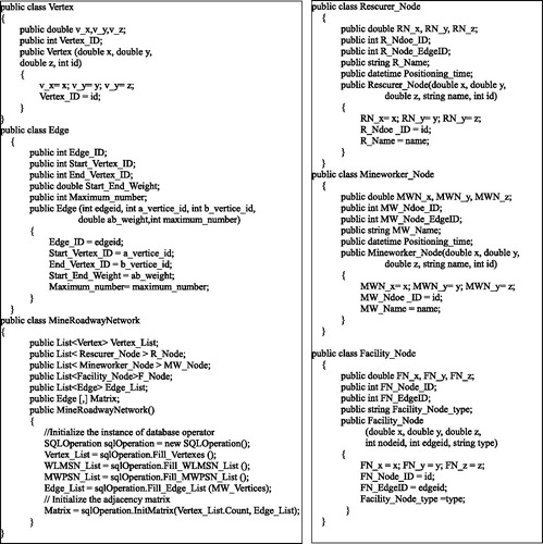
The objects in a physical network model are the geometric objects created in memory, and the data structures of them are the foundation of the rescue route planning algorithm. The data structures are defined through the following classes written with C# code. The MineRoadwayNetwork class defines the data structure of the roadway network, which is actually a directed graph. There are two edges with opposite directions between two adjacent vertexes, conversely, there is no edge between two non-adjacent vertexes. As a member of the MineRoadwayNetwork class, the Matrix is an asymmetric adjacency matrix, which records the topological connectivity, their directions, and weights of edges. The element Mij in Matrix is the edge, whose start vertex’s ID is i (denoted as Vi), and end vertex’s ID is j (denoted as Vj). If Vi and Vj are not adjacent, the element Mij is assigned an empty value, “Null”. The rescue route planning algorithm is programmed based on the adjacency matrix.
The data structure of 3 D roadway network model is shown as .
Figure 1. Data structure of 3 D roadway network model.
2.3. Data storage of objects
The data of various objects in the network model are stored in the SQL Server database tables and used to create the objects in memory according to corresponding classes.
The vertex table stores the information including ID, type and 3D coordinates of the point objects representing vertex elements.
The edge table stores the information including ID, IDs of vertexes, IDs of nodes, roadway length, roadway slope, and roadway water level of line objects representing edge elements.
The facility table stores the information including ID, type and 3D coordinates of the point objects representing various auxiliary facilities in the roadway, such as flow meters for monitoring water flow, personnel positioning equipment, etc.
The rescue personnel information tables store the information including ID, type and 3D coordinates of the point objects representing the rescuer elements.
The underground mineworker information tables store the information including ID, type and 3D coordinates of the point objects representing the mineworker elements.
2.4. The weights of the edges
When the optimal rescue route is being planned, an indicator is needed to measure the optimization of the rescue route. The length, slope and water level of each edge in the network are important factors affecting the accessibility of the roadway and the speed of rescuers and mineworkers, so the factors determine the optimization of the rescue route. Therefore, these factors are quantified as the weights of each edge. The weights of the factors are combined to be a comprehensive weight as the final indicator to measure optimization of the edge. The sum of the comprehensive weights of all edges in the rescue route is the final optimization indicator of the rescue route. The weight quantification of the factors and the calculation of the comprehensive weight are addressed as follows. It is different from the evacuations in fire disaster scenario, in which the indicators including heat release rate, generation of harmful fire gases, smoke, burning rate of the material, generated heat from fire, should be considered to calculate weights. In addition, the mining roadway weights calculating models are significantly different between them (Adjiski et al. Citation2015).
2.4.1. The influence coefficient of the slope factor
The slope of the roadway has a certain influence on the rescue speed, the time cost and the physical strength of rescuers, so it is necessary to quantify the influence coefficient of the slope factor. The distance and height difference of each edge can be calculated with the 3 D coordinates of the vertexes of the edge, and then slope value of the edge can be calculated with the arcsine function. For the same roadway, there are two walking directions, which are ascending direction and descending direction. The slope value is positive in ascending direction and negative in descending direction. The walking difficulty increases as the slope value increases in the ascending direction. In the descending direction, if the absolute value of the slope is less than 30, the walking difficulty decreases as the absolute value of the slope increases, else the walking difficulty increases as the absolute value of the slope increases. With reference to the relevant research (Zhao et al. Citation2015; Zhao and Zong Citation2015) and the actual situation of mine roadway, the rules to determine the influence coefficient of the slope factor are refined as shown in .
Table 1. The influence coefficient of the slope factor.
2.4.2. The influence coefficient of water level factor
When the water inrush hazard occurs, a large amount of water flows into the roadway from one or more positions in practical occasion. In this study, the inrush positions and the flow are simulated with simulation software. The water in the roadway affects the rescue speed and safety of rescuers and mineworkers. Therefore, the influence of water level factor should be considered when the rescue route is being planned. Currently, the water level in mine roadway can be monitored in real-time with water level sensors and transferred with the reliable communication network to the rescue database. The walking difficulty increases as the water level increases until the roadway is impassable. By referring to the relevant research (Fang et al. Citation2011; Wang, Zhang, and Li Citation2014; Cheng, Zhang, and Li Citation2014; Zhao et al. Citation2015; Zhao and Zong Citation2015; Wang Citation2017), and also according to the actual situation of roadway, the influence coefficient of water level in the roadway is shown in .
Table 2. The influence coefficient of water level factor.
2.4.3. The dynamic comprehensive weight
The length and the slope are the unvarying geometric attributes of the roadway, while the water level is the varying attribute in real-time of it. Therefore, the length and the slope of the roadway are the static factors whereas the varying water level is dynamic factor, which affect the accessibility of the roadway. The influence coefficient of water level should be calculated in real-time while the rescue route is being planned. To measure the total influence of all factors, the influence coefficients are combined into the dynamic comprehensive weight defined as Eq. (1).
(1)
(1)
Where is comprehensive weight of the roadway edge between vertex i and vertex j;
is the 3 D length of the edge;
is the slope influence coefficient of the edge;
is the water level influence coefficient of the edge. The comprehensive weight is also called the optimal relative length in previous research (Wang, Zhang, and Li Citation2014; Zhao et al. Citation2015; Zhao and Zong Citation2015; Wang Citation2017; Dong et al. Citation2018).
3. Rescue route planning
The main task of the simulation is to rescue the mineworkers underground, not to guide the mineworkers to escape. In the process of guiding the mineworkers, the rescuers need not go underground to search for the mineworkers, only need monitor positions of the mineworkers and inform them the current optimal escape route. While in the process of rescuing the mineworkers, the position of the mineworkers may be changing, so the rescuers should search for the mineworkers in the first step and find them. Then, the rescuers take the mineworkers to the mineworkers to the up ground. Therefore, the rescue process includes the following two steps: (1) the rescuers go underground to search for the mineworkers along the mine roadways; (2) the rescuers take the mineworkers back to the ground surface. Correspondingly, the rescue route planning should include two processes, the route planning for mineworker-search and the route planning for rescue return.
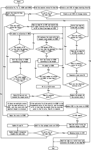
The rescue route planning algorithm is a combination of the Breadth-first search of the graph and the Dijkstra algorithm. First of all, this paper mainly draws on the idea of Breadth-first search when designing the rescue route planning algorithm. The search process starts from the starting point and expands outward through the boundary between the searched vertices and the unsearched vertices. In the route expansion process, the route search can skip the invalid route and the unreachable route by setting the judgment condition. Breadth-first search can calculate all reachable routes from the start point to the target point, but when the number of vertices in the graph is large, the search efficiency is very low. In order to improve the efficiency of route search, the search process of the rescue route is optimized based on the idea that the Dijkstra algorithm (Xu et al. Citation2007; Wang and Wu Citation2008; Deng et al. Citation2012; Wang Citation2012; Price and Ostfeld Citation2014; Hu, Yang, and Huang Citation2016). There are two aspects to the specific optimization. One is to remove the route with the larger weight in the same route, and only keep one or more paths with smaller weights. Second, if the end vertex of one route
is the intermediate point of the other route
and the weight of the route
is greater than the weight from the start point to the vertex
in the route
then remove
from route set. Through the optimization of these two aspects, the number of routes in the set of routes to be searched can be greatly reduced, thereby improving the efficiency of route search. Therefore, the rescue route search algorithm designed in this paper can not only search the optimal route from the source point to the specified target point but also calculate the non-shortest route that can be reached from the source point to the target point.
3.1. Route planning for mineworker-search
When planning the search route for the mineworkers, the position of the rescuers is set as the source point, and the position of the mineworkers is set as the destination point. During the process of rescue, rescuers need to consider two dynamic factors, one is the varying water level in the roadway; the other is the moving positions of the rescuers and the mineworkers. The planned route should be dynamically adjusted according to the changes of the factors. According to the 3 D network model described above, the weighted directed graph is defined as where
are the set of vertexes in the graph,
are the set of edges in the graph, and
is an asymmetric adjacency matrix, which records the topological connectivity among vertexes. Instead of directly storing the weight between the two vertexes, the edge, the starting vertex and the end vertex of the edge, and the weights in two directions are stored in the matrix. The advantage of this is that when the weight of an edge varies, the weight of the corresponding edge in the adjacency matrix is automatically updated. Combining Breadth-first search idea and Dijkstra algorithm, the process of route planning for mineworker-search underground is described as follows:
The R_Node (the rescue personnel node) in the network is set to the source point
(normally it is the mine exit), and the MW_Node (the mineworker node) is set to the target point
The vertex
If
Where
Select the route
Select the edge
Determine whether the target point
If the total number of routes in the set
If there are multiple routes with the same end vertex in the set
In the set
Update the set
The route with the smallest cumulative weight in
The current source point
The overall weight of each edge in the adjacency matrix (Matrix) is dynamically updated based on the water level of each roadway, which can be obtained either from a simulation or real-time monitoring.
Steps (1)∼(13) are executed repeatedly until the source point
A combination of all the planning routes in
The flow chart of the route-planning algorithm for mineworker-search is shown as .
Figure 2. The flow chart of the route-planning algorithm for mineworker search.
3.2. Route planning for rescue return
Route planning for rescue return should be executed when the rescuers find the mineworkers. The route planning for rescue return algorithm is similar to the route-planning algorithm for mineworker-search, with two differences: (1) In the route planning for rescue return process, the rescuers and the mineworkers are in the same position, therefore the or
in the network is set as the source point
and the
(normally the exit of the well) is set as the destination point
(2) The destination point
does not change under normal conditions, so it is unnecessary to dynamically update
Only the current source point,
needs to be updated according to the latest coordinates,
of the rescuers and
of the mineworkers. Therefore, all the steps in the mineworker-search route planning algorithm are the same as the route planning for rescue return algorithm except for steps (1) and (8). Steps (1) and (12) are modified as follows:
The R_Node or MW_Node in the network is set as the source point
The current source point
4. Simulation experiments and results
4.1. Constructing a 3 D network of roadways
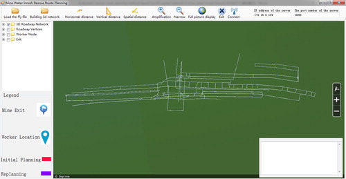
A 3 D network of roadways is constructed based on the plane drawing of mining engineering in this paper. The MineRoadwayNetwork class designed in this paper is used to create geometric objects in the 3 D roadway network model in the computer memory. Based on the TerraExplorer 6.6.1 development library provided by the Skyline platform, the 3 D rescue route planning simulation system is developed. The static objects, such as 3 D tunnel bodies, and the dynamic objects, such as rescue routes and personnel positions, are built in the system. The rescue route planning simulation function and some auxiliary functions such as distance measurement, view control operation and network communication are implemented in the system. The main interface of the system is shown in .
Figure 3. The 3 D scene and models in the simulation system.
4.2. Simulation of walking speed and water level
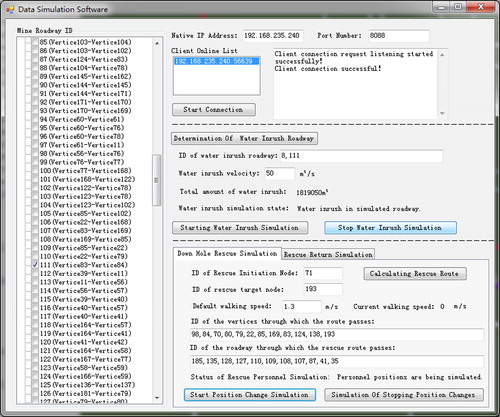
The data simulation software running on the server is used to dynamically simulate the water level of each roadway as well as the speeds and current position of underground rescuers and mineworkers. The simulated data is transmitted in real time through the TCP/IP protocol to the simulation system running on the client. The data simulation software is shown as .
Figure 4. Data simulation software.
4.2.1. Simulation of walking speed
According to the related literature (Fang et al. Citation2011), the moving speed of the underground personnel in the horizontal roadway is set to by default. The default movement speed of the underground personnel in the horizontal roadway can be modified according the actual situation with the data simulation software. The slope and water level of roadway are two important factors that affect the walking speed, and they correspond to two coefficients named
and
as defined in Section 2.3. The walking speed is calculated with Eq.(3).
(3)
(3)
Where denotes the actual walking speed between vertex
and vertex
denotes the influence coefficient of the slope of the roadway;
denotes the influence coefficient of the water level of the roadway.
The time it takes to walk to the next position is calculated based on the ratio of the length of the current roadway to the walking speed of the person. The time is calculated with Eq.(4).
(4)
(4)
Where denotes the length of the roadway between vertex
and vertex
denotes the walking speed when the rescuers walks on the roadway between the vertex
and the vertex
According to the speed and time, the simulated position of the rescuers at any time in the roadway can be calculated. The position is calculated with Eq.(5).
(5)
(5)
Where denotes the
coordinate of the rescuers' current position;
denotes the
coordinate of the rescuers' current position;
denotes the
coordinate of the rescuers' current position;
denotes the
coordinate of the starting point of the roadway;
denotes the
coordinate of the starting point of the roadway; and
denotes the
coordinate of the starting point of the roadway.
4.2.2. Simulation of water level
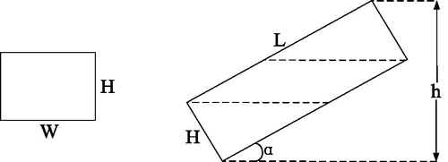
The water capacity of each roadway in the mine is fixed, but the water yield is dynamic and the number of water inrush points may increase. The mine water level monitoring system based on the Internet of Things and sensing technologies can collect the water level of mine roadways in real time and realize real-time transmission, storage and remote access of monitoring data. Due to the absence of sensor water level monitoring data, the dynamic water level simulation software is developed to calculate the dynamic change of water level in the roadway in this study. In order to carry out the simulation and calculation, it is assumed that the mine roadway is in shape of cuboid, the water volume per unit length of each roadway is the same. When the water volume per second filled in the roadway is a constant, hence the real-time water level in each roadway can be calculated. The water level is calculated with Eq. (6) (Ma and Liu Citation2015).
(6)
(6)
Where denotes the height of the water level in the roadway;
denotes the amount of water in the roadway;
denotes the inclination angle of the roadway;
denotes the width of the underside of the roadway;
denotes the length of the roadway; and
denotes the height of cuboid of the roadway. The parameters are indicated in the .
Figure 5. The diagram of parameters in the water level calculating equation.
4.3. Dynamic rescue route planning simulation
4.3.1. Simulation of route planning for mineworker-search
It is assumed that the mineworkers at vertex V need to be rescued because of the water inrush into the mine. After starting the water inrush simulation, the water inrush rate is set as 600 m^3/h. At the beginning of the rescue route planning, take the mine entrance point (vertex V71) as the starting point, and vertex V193 as the target point to carry out the rescue route analysis. According to the current weights of the edges in the 3 D roadway network, the route-planning algorithm for mineworker-search is executed. Fourteen potential routes are searched in total by the algorithm, three routes with smaller weights are list in , and the route with least weight (Route 1) is the current optimal route. The IDs of the vertices on the planned route for mineworker-search are sequentially listed in .
Table 3. The first three routes with smaller weights searched in initial planning for mineworker-search.
The route-planning algorithm for mineworker-search is executed repeatedly after the initial planning, because the weights of the edges and the positions of the rescuers and mineworkers are dynamic. At the beginning of each re-planning phase, the starting point and the target point are updated according to the current positions of the rescuers and the mineworkers. For example, at the beginning of the re-planning, the starting point is the vertex V98 and the target point is still the vertex V193. However, the weight of the E111 roadway between the vertex V84 and the vertex V83 changes, and the roadway becomes impassable. At this time, two routes are searched in total by the algorithm, as shown in , the route with least weight (Route 1) is the current optimal route. Therefore, the re-planned route is different from the initial planned route, as can be seen in and . Until the position of rescuers coincides with the position of mineworkers, the process of route planning for mineworker-search remains unfinished.
Figure 6. Simulation of route planning for mineworker-search.
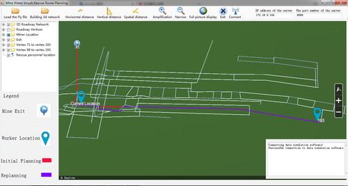
Table 4. The potential routes searched in re-planning for mineworker-search.
The rescue route planning is dynamically simulated with the 3 D rescue route planning simulation system, and the results are displayed in . The IDs of vertices and roadways in the rescue route are listed in . In order to make the rescue route clearer, the corresponding IDs on the route are not shown in . The red route in the Figure is the rescue route for the initial planning, and the purple route is the re-planned rescue route. The re-planned rescue route successfully avoided the flooded E111 roadway.
Table 5. The edges in the optimal routes searched in initial planning and re-planning for mineworker-search.
4.3.2. Simulation of route planning for rescue return
When the process of route planning for mineworker-search is complete, the process of route planning for the rescue return begins. The planning algorithms in the two processes are similar, however, except that the starting point (vertex V71) in the previous planning process is set as the target point in the return planning process, and the current target point (vertex V193) in the previous planning process is set as the starting point in the return planning process. At this time, there are 2 routes are searched in total by the route-planning algorithm for rescue return, as shown in , the route with least weight (Route 1) is the current optimal route for rescue return.
Table 6. The potential routes with smaller weights searched in planning for rescue return.
The IDs of the vertices on the planned return route and the IDs of the edges of planned return route are sequentially listed in . The red route is the planned return route as shown in . It can be seen that the planned route for mineworker-search and the planned route for rescue return do not overlap perfectly, because the weights of the edges in the 3 D roadway network vary dynamically during the two processes ().
Figure 7. Simulation of route planning for rescue return.
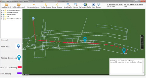
Table 7. The edges in the optimal routes searched in planning for rescue return.
5. Discussion
Mine roadways form a kind of network entity with typical three-dimensional spatial characteristics. There are topological relationships such as adjacency, intersection, and disjunction among the elements of the roadway network (Mei, Wu, and Liu Citation2013; Liu, Mao, and Mei Citation2015). In order to more vividly express such three-dimensional spatial relationships and feature information, the two-dimensional network model is extended to a three-dimensional roadway network model for the purposes of route planning in this paper. In the extended three-dimensional roadway network model, not only are the static vertices and network edges of the three-dimensional coordinates defined, but also the human entities are abstracted into movable, three-dimensional, dynamic nodes, and the various facilities in the underground are abstracted as non-movable, three-dimensional, static nodes. When determining the weight of the edges in the network, previous studies have quantified the factors affecting the passage and the length of the roadway as an equivalent path (Wang Citation2017) or equivalent length (Zhao et al. Citation2015). In order to highlight the dynamically changing characteristics of roadway accessibility, the product of the roadway length the roadway slope influence coefficient
and the roadway water level influence coefficient
is proposed as the dynamic integrated weight for each edge in in this paper. The costs of ascending and descending a given sloped roadway are not consistent. Therefore, the edges between vertices are no longer defined as directed or undirected, but as bi-directional edges with different weights in each direction.
During the rescue route planning, a rescue route search algorithm combining the Breadth-first search idea and the Dijkstra algorithm (Wang Citation2012; Wang Citation2017) is designed. The Breadth-first search algorithm can be used to calculate all accessible routes from a single source point to a single target, but when the number of vertices in the graph is large, its computational efficiency is very low. The Dijkstra algorithm can be used to calculate a shortest route from a single source point to other vertices, but not to calculate reachable non-shortest routes from a single source point to other vertices. In this paper, the two algorithms are effectively combined when designing the single-target rescue route planning algorithm so that the single-target rescue route planning algorithm can calculate the shortest route from the specified source point to the specified target point and the non-shortest passable route at the same time.
In previous studies, the path was not dynamically adjusted during the rescue (Yao et al. Citation2011; Wu, Lei, et al. Citation2013; Adjiski et al. Citation2015) planning or escape (Jalali and Noroozi Citation2009) route planning. In this paper, a dynamic adjustment method is designed for the rescue route planning, so that the planned route is more in line with the actual needs of the emergency rescue. There are two advantages to dynamically adjust the route during the rescue process. First, the water level in the roadway is dynamically changing. When one of the planned rescue routes becomes impassable, the rescue route needs to be re-planned. With reference to previous relevant research, the influence coefficients of the roadway slope (Zhao et al. Citation2015; Zhao and Zong Citation2015), the roadway water level (Fang et al. Citation2011; Wang, Zhang, and Li Citation2014; Cheng, Zhang, and Li Citation2014; Zhao et al. Citation2015; Zhao and Zong Citation2015; Wang Citation2017), and the water flow (Ma and Liu Citation2015; Li et al. Citation2013) are considered in the route-planning algorithm in this paper. Second, the position of the target may change before the rescuer reaches the target, so this factor is also considered in the algorithm. This gives the route planning method proposed in this paper a certain degree of rationality. At present, the 3 D network is an ideal model, and some complex conditions, such as equipment barriers and road roughness in the roadway, are not considered in this study. In addition, the algorithm proposed is suitable for rescue route planning, but not for self-rescue guiding. We will improve the model and the algorithm in further studies to account for more real-world conditions.
6. Conclusion
In order to solve the route planning problem during a mine water inrush hazard rescue operations, this paper constructs a mine 3 D network model of mine roadways, proposes a rescue route planning algorithm, and simulates an instance of single-target rescue route planning. The research in this paper has the following advantages:
Object-oriented thinking is used to construct a roadway network data model suitable for mine water inrush hazard route planning. When setting the weights of the edges in the roadway network model, the concept of dynamic integrated weight is proposed. The dynamic comprehensive weight accounts for the influence coefficients of both the roadway water level and the roadway slope as well as the spatial distance, so as to characterize the traffic capacity of all roadways in the mine during the water inrush event.
The rescue route planning is divided into two processes: route planning for mineworker-search underground and route planning for rescue return. Based on the idea of graph Breadth-first search and the Dijkstra algorithm, the single-objective rescue route planning algorithm is designed and implemented. The rescue route calculated using this algorithm is not only shorter but safer as well.
This paper designs a simulation experiment in a 3D scene. In the simulation experiment, when the weight of the planned route is updated, the route planning algorithm dynamically adjusts the planned rescue route to account for current personnel positions and roadway water levels.
Acknowledgments
The authors are grateful to the editor and the reviewers for their valuable comments and suggestions for this paper.
Disclosure statement
No potential conflict of interest was reported by the authors.
Additional information
Funding
Related Research Data
References
- Adjiski V, Mirakovski D, Despodov Z, Mijalkovski S. 2015. Simulation and optimization of evacuation routes in case of fire in underground mines. J Sust Mining. 14(3):133–143.
- Alexiou D, Tsouros C. 2017. Design of an irrigation network system in terms of canal capacity using graph theory. J Irr Drain Eng. 143(6):06017002.
- Cheng SH, Zhang XY, Li FL. 2014. Application of k shortest path algorithm in avoiding from mine water hazard. Metal Mine. 43(1):137–140. (in Chinese with English Abstract)
- Cui YH. 2015. Application and research on shared ontology model of coal mine emergency cases. Proceedings of the Aasri International Conference on Industrial Electronics and Applications (IEA 2015). 2, p. 405–409.
- Dash AK, Bhattacharjee RM, Paul PS. 2016. Lessons learnt from Indian inundation hazards: an analysis of case studies. Int J Hazard Risk Red. 20:93–102.
- Deng Y, Chen Y, Zhang Y, Mahadevan S. 2012. Short communication: fuzzy Dijkstra algorithm for shortest path problem under uncertain environment. Appl Soft Comput. 12(3):1231–1237.
- Dong LL, Zhang HL, Zhang X, Ye N. 2018. Research on the optimal escape path algorithm in mine water bursting hazard. J Comput Methods Sci Eng. (14):1–18.
- Fang YM, Chen J, Ai CL, Zhang CL, Zhou SY, Fu XJ, Gu DM. 2011. Real-time emergency route generating algorithm in tunnel. Trans Nonfer MetalsSoc China. 21(s3):s637–s641.
- He Z, Wu Q, Wen L, Fu G. 2019. A process mining approach to improve emergencyrescue processes of fatal gas explosion accidents in Chinese coal mines. Safety Sci. 111:154–166.
- Huang S.J, Dinavahi V. 2018. Fast distribution network reconfiguration with graph theory. 12(13):3286–3295.
- Huang Y. 2017. Research on the improvement of Dijkstra algorithm in the shortest path calculation. Proceedings of the 2017 4th International Conference on Machinery, Materials and Computer (MACMC 2017). 150, p. 745–749.
- Hu L, Yang J, Huang J. 2016. The real-time shortest path algorithm with a consideration of traffic-light. J Intel Fuzzy Syst. 31(4):2241–2403.
- Hwang JY, Kim JS, Lim SS, Park KH. 2003. A fast path planning by path graph optimization. IEEE Trans Syst Man Cyber: Part A. 33(1):121–129.
- Jalali SE, Noroozi M. 2009. Determination of the optimal escape routes of underground mi-ne networks in emergency cases. Safety Sci. 47(8):1077–1082.
- Li C, Li J, Li Z, Hou D. 2013. Establishment of spatiotemporal dynamic model for water inrush spreading processes in underground mining operations. Safety Sci. 55:45–52.
- Likaj R, Shala A. 2017. Application of graph search algorithm Dijkstra to find optimal solution for the problem of transport. Annal Faculty Eng Hunedoara - Int J Eng. 15(4):69–72.
- Liu PY, Mao SJ, Mei LI. 2015. Key technology and application of auto processing to topological relationship of 3D roadway in coal mine. Coal Sci Technol. 43(4):56–81. (in Chinese with English Abstract).
- Ma H, Liu C. 2015. Searching algorithm of mine water inrush paths and its application. J Safety Sci Technol. 11(11):35–40. (in Chinese with English Abstract)
- Ma J, Zhang Y. 2012. A new dynamic assessment for multi-parameters information of water inrush in coal mine. The International Conference on Power Electronics and Intelligent Transportation System.16, p. 1586–1592.
- Mei L, Wu J, Liu P. 2013. Three-dimensional roadway topological modeling and visualization technique for mines International Conference on Geoinformatics.
- Price E, Ostfeld A. 2014. Optimal water system operation using graph theory algorithms. Procedia Eng. 89:502–508.
- Qi Y, Li M, Li K, Yeh T.C.J. 2017. Spatiotemporal development of mine water inrush and its mechanism—a case study in Ganhe coal mine, Shanxi, China. Arab J Geosci. 10(19):433.
- Şalap S, Karslıoğlu M.O, Demirel N. 2009. Development of a GIS-based monitoring and management system for underground coal mining safety. Int J Coal Geol. 80(2):105–112.
- Sheu JB. 2007. An emergency logistics distribution approach for quick response to urgent relief demand in hazards. Transp Res Part E Log Transp Rev. 43(6):687–709.
- Wang JH, Zhang YJ, Li YP. 2014. Mathematical modeling and algorithm’s research of optimal hedge underground path’ s GIS network analysis. J China Coal Soc. 39(s2):411–415. (in Chinese with English Abstract)
- Wang R. 2017. A research on the weighted improvement of Dijkstra algorithm in optimalpath calculation. 5th International Conference on Frontiers of Manufacturing Science and Measuring Technology. Advances in Engineering Research (AER),130, p. 159–163.
- Wang SX. 2012. The improved Dijkstra's shortest path algorithm and its application. Procedia Eng. 29:1186–1190.
- Wang Y, Wu F. 2008. Improvement of Dijkstra algorithm for optimal hazard avoidance route in mine emergency rescue. Industr Automat. 2008(5):13–15. (in Chinese with English Abstract)
- Wu B, Lei B.W, Yu Z.J, Zhao Z.Y, Guo Z.G. 2013. Study on the coal mine emergency rescue information management system based on WebGIS. Adv Mater Res. 765–767:928–935.
- Wu J, Xu S, Zhou R, Qin Y. 2016. Scenario analysis of mine water inrush hazard using Bayesian networks. Safety Sci. 89:231–239.
- Wu Q, Cui F.P, Zhao S.Q, Liu S.Q. 2013. Type classification and main characteristics of mine water hazards. J China Coal Soc. 38(4):561–565. (in Chinese with English Abstract)
- Wu Q, Zhou W, Guan E. 2009. Emergency responses to water hazards in coalmines, China. Environ Geol. 58(1):95–100.
- Wu Y.B, Huang M, Liu B, Cui F. 2009. Decision of assistant mine hazards aid based on 3D roadway model and its implementation by 3D GIS. International Conference on Chinese Control and Decision Conference. IEEE Press, p. 3963–3966.
- Xu C, Gong P. 2011. Water hazard types and water control measures of Hanxing coal mine area. Procedia Earth Planetary Sci. 3(3):343–348.
- Xu MH, Liu YQ, Huang QL, Zhang YX, Luan GF. 2007. An improved Dijkstra’sshortest path algorithm for sparse network. Appl Math Comput. 185(1):247–254.
- Yao HW, Dong WL, Liang D, Arnd R, Wei LJ. 2011. Application of GIS on emergency rescue. Procedia Eng. 11(11):185–188.
- Yuan Y, Wang D. 2009. Path selection model and algorithm for emergency logistics management. Comput Ind Eng. 56(3):1081–1094.
- Zhao ZP, Song GJ, Zong YY, Li XB, Kang QH, Zhang XT, Wang YH, Xu XZ. 2015. Research on the multi-optimal paths of coal mine floods based on the D-K algorithm. J China Coal Soc. 40(2):397–402. (in Chinese with English Abstract).
- Zhao ZP, Zong YY. 2015. A multi-path algorithm implemented with bidirectional search of mine water inrush hedge. School Comp Sci Technol, China Univ Mining Technol. 44(3):590–596. (in Chinese with English Abstract).
- Zuecco G, Rinderer M, Penna D, Borga M, van Meerveld Hj. 2019. Quantification of subsurface hydrologic connectivity in four headwater catchments using graph theory. Sci Total Environ. 646:1265–1280.